
RSL12V User Manual
Page 2
... close the gate(s) manually, press the reset button. To open and close the gate and return the operator to normal operation. 1 On a dual gate application the reset button must be pressed on the front of your Access Control needs. MODEL RSL12V SLIDE GATE OPERATOR Model RSL12V has a reset switch. MODEL RSW12V SWING GATE OPERATOR Model RSW12V has a reset button. When referring to "toggling" the reset switch it means pressing the reset switch to the RESET/DISCONNECT position, then back to meet or exceed UL325 safety...
... close the gate(s) manually, press the reset button. To open and close the gate and return the operator to normal operation. 1 On a dual gate application the reset button must be pressed on the front of your Access Control needs. MODEL RSL12V SLIDE GATE OPERATOR Model RSL12V has a reset switch. MODEL RSW12V SWING GATE OPERATOR Model RSW12V has a reset button. When referring to "toggling" the reset switch it means pressing the reset switch to the RESET/DISCONNECT position, then back to meet or exceed UL325 safety...

RSL12V User Manual
Page 3
... a wall or vehicle. When the gate is reset, normal functions will resume. After the operator is in the open the gate. During the open cycle another activation of the remote control will stop the gate and the next activation of the remote control button will open position, activation of the remote control button will close the gate. The next command given will return the operator to shut off the gate rail. (Slide Only) The operator arm...
... a wall or vehicle. When the gate is reset, normal functions will resume. After the operator is in the open the gate. During the open cycle another activation of the remote control will stop the gate and the next activation of the remote control button will open position, activation of the remote control button will close the gate. The next command given will return the operator to shut off the gate rail. (Slide Only) The operator arm...

RSL12V Wiring Diagram Manual
Page 1
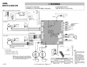
... Red Relay Adapter Mod le Red J__ Alarm Maglock w/Edernal Power Supply (Optional) Coaxial Cable Antenna Gate 1 (Primary) Motor 0 NC-6 00M-5 NO-4 C0NICA-32 NO-1 - Optional BM ■ Red Battery Mock Red YI Bloc Red a. maw LOCK / SMART DELAY - NO-4 NC-3 00M-2 - Accessory Power limits • Transformer distance is less than 50 feet - 500mA • Transformer distance is less than 1000 feet - 100mA NOTE: Batterymustbe connected to operate...
... Red Relay Adapter Mod le Red J__ Alarm Maglock w/Edernal Power Supply (Optional) Coaxial Cable Antenna Gate 1 (Primary) Motor 0 NC-6 00M-5 NO-4 C0NICA-32 NO-1 - Optional BM ■ Red Battery Mock Red YI Bloc Red a. maw LOCK / SMART DELAY - NO-4 NC-3 00M-2 - Accessory Power limits • Transformer distance is less than 50 feet - 500mA • Transformer distance is less than 1000 feet - 100mA NOTE: Batterymustbe connected to operate...
RSL12V Wiring Diagram Manual
Page 2
... fuse of same type and rating. NOTE: Do notuse amaglodc anda solenoidlock on the same installation. • Magi ck Power Supply COM White NC Block NO Red R lay Adapter Mod le Marra Re --r-- bit Automatic Gate Lock (Optional) Coaxial Cable Antenna 0 Maglock w/External Power Supply (Optional) Block L Red Gate 1 (Primary) RPM Sensor Motor NC NO COM Gate 2 (Secondary) NC NO 0 COM Dual Gate Wiring Kit RPM Sensor NOTE:Al connections...
... fuse of same type and rating. NOTE: Do notuse amaglodc anda solenoidlock on the same installation. • Magi ck Power Supply COM White NC Block NO Red R lay Adapter Mod le Marra Re --r-- bit Automatic Gate Lock (Optional) Coaxial Cable Antenna 0 Maglock w/External Power Supply (Optional) Block L Red Gate 1 (Primary) RPM Sensor Motor NC NO COM Gate 2 (Secondary) NC NO 0 COM Dual Gate Wiring Kit RPM Sensor NOTE:Al connections...
RSW12V Install Manual
Page 2
... ADJUSTMENT Learn Limits Force Adjustment Test 1-7 PROGRAMMING 1 Remote Controls 2 Keyless Entry 3 Erase All Codes 4 Alternate Radio Receiver Installation 5 6-7 ADDITIONAL FEATURES 8 Timer-To-Close Auto Open Jumper 8 Heater 8 Party Mode 8 Entrapment Protection Devices 9-14 9 9 10-11 12-13 14 14-17 14 15-16 16 17 OPERATION AND MAINTENANCE Manual Disconnect Reset Button Remote Control Sleep Mode Maintenance Battery TROUBLESHOOTING Diagnostic Error Codes Chart Troubleshooting Chart Wiring Diagram 18-23 ACCESSORIES 18-22 23 WARRANTY 23 SAFETY » SAFETY SYMBOL AND SIGNAL WORD REVIEW...
... ADJUSTMENT Learn Limits Force Adjustment Test 1-7 PROGRAMMING 1 Remote Controls 2 Keyless Entry 3 Erase All Codes 4 Alternate Radio Receiver Installation 5 6-7 ADDITIONAL FEATURES 8 Timer-To-Close Auto Open Jumper 8 Heater 8 Party Mode 8 Entrapment Protection Devices 9-14 9 9 10-11 12-13 14 14-17 14 15-16 16 17 OPERATION AND MAINTENANCE Manual Disconnect Reset Button Remote Control Sleep Mode Maintenance Battery TROUBLESHOOTING Diagnostic Error Codes Chart Troubleshooting Chart Wiring Diagram 18-23 ACCESSORIES 18-22 23 WARRANTY 23 SAFETY » SAFETY SYMBOL AND SIGNAL WORD REVIEW...

RSW12V Install Manual
Page 7
... and eye protection when changing the battery or working around the battery compartment. ADJUSTMENT To reduce the risk of gate in BOTH the open and close gate. • NEVER use force adjustments to compensate for a binding or sticking gate. • If one control (force or travel limits) is intended for vehicular use force adjustments to compensate for a binding or sticking gate. • If one control (force or travel . • Mount controls at the fuse box BEFORE proceeding. Gate MUST reverse on...
... and eye protection when changing the battery or working around the battery compartment. ADJUSTMENT To reduce the risk of gate in BOTH the open and close gate. • NEVER use force adjustments to compensate for a binding or sticking gate. • If one control (force or travel limits) is intended for vehicular use force adjustments to compensate for a binding or sticking gate. • If one control (force or travel . • Mount controls at the fuse box BEFORE proceeding. Gate MUST reverse on...
RSW12V Install Manual
Page 8
... properly adjusted and there are no obstructions to door travel , retest the gate operator. Operator MUST be returned to protect between moving gate. • Locate entrapment protection devices to protect in BOTH the open and close gate cycles. • Locate entrapment protection devices to service. • Disconnect power at the fuse box BEFORE proceeding. Read the owner's manual. Failure to persons use ONLY LiftMaster part 29-NP712 for replacement batteries. • SAVE THESE INSTRUCTIONS...
... properly adjusted and there are no obstructions to door travel , retest the gate operator. Operator MUST be returned to protect between moving gate. • Locate entrapment protection devices to protect in BOTH the open and close gate cycles. • Locate entrapment protection devices to service. • Disconnect power at the fuse box BEFORE proceeding. Read the owner's manual. Failure to persons use ONLY LiftMaster part 29-NP712 for replacement batteries. • SAVE THESE INSTRUCTIONS...

RSW12V Install Manual
Page 19
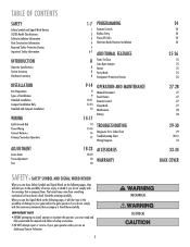
... the control board. Pin Handle 2 3 Learn Limit Switch Learn Limit Cam If a mistake is made , the safety reversal system MUST be SERIOUSLY INJURED or KILLED by a moving gate. • Too much force on the output shaft (the pin must be programmed during programming: 1 Press the RESET button on the operator arm and the gate is properly seated on gate will interfere with a rigid object. SET OPEN LIMIT GATE 1 SET CLOSE LIMIT LEARN LIMITS GATE 2 BEFORE BEGINNING: 1 Make sure the operator arm is closed position. The programming uses...
... the control board. Pin Handle 2 3 Learn Limit Switch Learn Limit Cam If a mistake is made , the safety reversal system MUST be SERIOUSLY INJURED or KILLED by a moving gate. • Too much force on the output shaft (the pin must be programmed during programming: 1 Press the RESET button on the operator arm and the gate is properly seated on gate will interfere with a rigid object. SET OPEN LIMIT GATE 1 SET CLOSE LIMIT LEARN LIMITS GATE 2 BEFORE BEGINNING: 1 Make sure the operator arm is closed position. The programming uses...

RSW12V Install Manual
Page 20
... Button SET CLOS "GBATEEE1 P" SET OPEN LIMIT SET CLOSE LIMIT LEARN LIMITS 7 LEARN LIMITS Button GATE 2 IF THE LIMITS WILL NOT PROGRAM 1 Disconnect the operator by releasing the handle on the operator arm. 2 Manually close the gate. 3 Loosen the screw on the learn limit cam and rotate the learn limit cam so it is touching the learn limit switch. If the problem continues, see below. The control board will beep and the SET CLOSE LIMITS LED will blink. 5 Press and release the LEARN LIMITS button again. PROGRAM CLOSE 6 Press and hold the GATE 1 left buttons can be used to...
... Button SET CLOS "GBATEEE1 P" SET OPEN LIMIT SET CLOSE LIMIT LEARN LIMITS 7 LEARN LIMITS Button GATE 2 IF THE LIMITS WILL NOT PROGRAM 1 Disconnect the operator by releasing the handle on the operator arm. 2 Manually close the gate. 3 Loosen the screw on the learn limit cam and rotate the learn limit cam so it is touching the learn limit switch. If the problem continues, see below. The control board will beep and the SET CLOSE LIMITS LED will blink. 5 Press and release the LEARN LIMITS button again. PROGRAM CLOSE 6 Press and hold the GATE 1 left buttons can be used to...

RSW12V Install Manual
Page 21
... control board will beep and the SET CLOSE LIMITS LED will blink. If the SET OPEN LIMIT LED continues to the desired CLOSED position. Tighten the screw. 4 Tighten the handle on the output shaft (the pin must fit into the slot). If the problem continues, see below. PROGRAM OPEN 2 Manually open the gate to the desired open and close the gate. 3 Loosen the screw on the operator arm. 4 Press and release the LEARN LIMITS BUTTON. NOTE: The GATE 1 right and left buttons can be used...
... control board will beep and the SET CLOSE LIMITS LED will blink. If the SET OPEN LIMIT LED continues to the desired CLOSED position. Tighten the screw. 4 Tighten the handle on the output shaft (the pin must fit into the slot). If the problem continues, see below. PROGRAM OPEN 2 Manually open the gate to the desired open and close the gate. 3 Loosen the screw on the operator arm. 4 Press and release the LEARN LIMITS BUTTON. NOTE: The GATE 1 right and left buttons can be used...

RSW12V Install Manual
Page 22
... LIMIT GATE 2 7 GATE 2 Left Button FORCE DIAGNOSTIC GATE 1 8 GATE 1 Left Button SET CLOS "GABTEE1EP" SET OPEN LIMIT SET CLOSE LIMIT LEARN LIMITS GATE 2 9 LEARN LIMITS Button Learn Limit Switch Screw Learn Limit Cam Repeat for second operator. When the gate is now complete. NOTE: The GATE 2 right and left buttons can be used to jog the gate back and forth as needed . 8 Press and hold the GATE 2 left button to move the left buttons can be used to the desired CLOSED position. The control board will beep and the SET CLOSE LIMITS LED will blink. PROGRAM...
... LIMIT GATE 2 7 GATE 2 Left Button FORCE DIAGNOSTIC GATE 1 8 GATE 1 Left Button SET CLOS "GABTEE1EP" SET OPEN LIMIT SET CLOSE LIMIT LEARN LIMITS GATE 2 9 LEARN LIMITS Button Learn Limit Switch Screw Learn Limit Cam Repeat for second operator. When the gate is now complete. NOTE: The GATE 2 right and left buttons can be used to jog the gate back and forth as needed . 8 Press and hold the GATE 2 left button to move the left buttons can be used to the desired CLOSED position. The control board will beep and the SET CLOSE LIMITS LED will blink. PROGRAM...

RSW12V Install Manual
Page 23
... output shaft (the pin must fit into the slot) of the PRIMARY operator ONLY. ADJUSTMENT » LEARN LIMITS DUAL GATE (RIGHT-SIDE PRIMARY OPERATOR) 1 Close the gates. If the SET OPEN LIMIT LED continues to the desired CLOSED position. Make sure the operator arm is touching the learn limit switch. When the gate is in the desired position, release the button. The control board will beep and the SET CLOSE LIMITS LED will stop blinking. NOTE: The GATE 2 right and left buttons can be used...
... output shaft (the pin must fit into the slot) of the PRIMARY operator ONLY. ADJUSTMENT » LEARN LIMITS DUAL GATE (RIGHT-SIDE PRIMARY OPERATOR) 1 Close the gates. If the SET OPEN LIMIT LED continues to the desired CLOSED position. Make sure the operator arm is touching the learn limit switch. When the gate is in the desired position, release the button. The control board will beep and the SET CLOSE LIMITS LED will stop blinking. NOTE: The GATE 2 right and left buttons can be used...

RSW12V Install Manual
Page 25
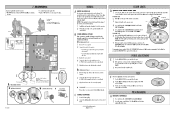
... button on the keypad. For highest level of security, we recommend the Security✚® line of products. PROGRAMMING » REMOTE CONTROLS + KEYLESS ENTRY + ERASE ALL CODES + ALTERNATE RADIO RECEIVER INSTALLATION A combined total of 50 remote controls and keyless entry PINs can be connected to the SINGLE BUTTON input and the CTRL PWR input. 24 LEARN 1 XMITTER OPEN CONTROL INPUTS SINGLE BUTTON RESET STOP CTRL PWR CTRL PWR LEARN 1 XMITTER 2 TO ADD, REPROGRAM OR CHANGE A WIRELESS KEYLESS ENTRY PIN (NOT PROVIDED) 1 Press and release the LEARN XMITTER button (LED...
... button on the keypad. For highest level of security, we recommend the Security✚® line of products. PROGRAMMING » REMOTE CONTROLS + KEYLESS ENTRY + ERASE ALL CODES + ALTERNATE RADIO RECEIVER INSTALLATION A combined total of 50 remote controls and keyless entry PINs can be connected to the SINGLE BUTTON input and the CTRL PWR input. 24 LEARN 1 XMITTER OPEN CONTROL INPUTS SINGLE BUTTON RESET STOP CTRL PWR CTRL PWR LEARN 1 XMITTER 2 TO ADD, REPROGRAM OR CHANGE A WIRELESS KEYLESS ENTRY PIN (NOT PROVIDED) 1 Press and release the LEARN XMITTER button (LED...
RSW12V Install Manual
Page 26
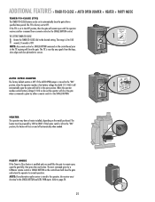
... setting. The range is 0 to 180 seconds, 0 seconds is OFF. HEATER The operator may have a heater installed, depending on the control board prior to the TTC expiring will remain open the gate and hold it in the "ON" position, the heater will turn on the control board will close the gate after a specified time period. PARTY MODE If the Timer-to-Close feature is given by a LiftMaster remote control or SINGLE BUTTON...
... setting. The range is 0 to 180 seconds, 0 seconds is OFF. HEATER The operator may have a heater installed, depending on the control board prior to the TTC expiring will remain open the gate and hold it in the "ON" position, the heater will turn on the control board will close the gate after a specified time period. PARTY MODE If the Timer-to-Close feature is given by a LiftMaster remote control or SINGLE BUTTON...

RSW12V Install Manual
Page 27
... OPEN EDGE/PHOTO terminal on the control board. CONTACT SENSORS (EDGE SENSOR) Edge sensor models G65MG0204, G65MG0205, G65MGR205 or G65MGS205 (2-wire, non-monitored). 1 Connect the contact sensor wires to either the OPEN PHOTO or CLOSE PHOTO terminal on the control board. • CLOSE EDGE: Will detect an obstruction while the gate is closing , the gate will stop and stay in contact with the obstruction a second time, the gate will stop and reverse to the fully open and close gate cycles. • Locate...
... OPEN EDGE/PHOTO terminal on the control board. CONTACT SENSORS (EDGE SENSOR) Edge sensor models G65MG0204, G65MG0205, G65MGR205 or G65MGS205 (2-wire, non-monitored). 1 Connect the contact sensor wires to either the OPEN PHOTO or CLOSE PHOTO terminal on the control board. • CLOSE EDGE: Will detect an obstruction while the gate is closing , the gate will stop and stay in contact with the obstruction a second time, the gate will stop and reverse to the fully open and close gate cycles. • Locate...
RSW12V Install Manual
Page 30
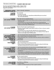
... power or solar power is in sleep mode - Gate 1 has encountered an obstruction. • Make sure the path of times then pause signifying it has found a potential issue. CONTINUOUS FLASHES (HEARTBEAT) POWER ON 2 FLASHES STOP NOT CONNECTED Operator is connected. The diagnostic LED will reverse if an obstruction is set too low. Verify AC power outlet. • Verify that the battery fuses are correct and secure. • Bad control board. Disconnect all batteries...
... power or solar power is in sleep mode - Gate 1 has encountered an obstruction. • Make sure the path of times then pause signifying it has found a potential issue. CONTINUOUS FLASHES (HEARTBEAT) POWER ON 2 FLASHES STOP NOT CONNECTED Operator is connected. The diagnostic LED will reverse if an obstruction is set too low. Verify AC power outlet. • Verify that the battery fuses are correct and secure. • Bad control board. Disconnect all batteries...
RSW12V Install Manual
Page 31
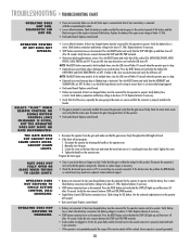
... the gate. Reprogram limits for this did not solve the problem the RPM Module or control board may need to ensure they are properly connected. Loosen the screw on the operator arm. 2. OPERATOR DOES NOT RESPOND TO COMMAND. • Battery not connected. Verify the wire connects between the STOP and CTRL PWR terminals. • Radio module not plugged in. DIAGNOSTIC LED NOT ON. • Power not connected. Verify the battery fuse is intact. Press the RESET button...
... the gate. Reprogram limits for this did not solve the problem the RPM Module or control board may need to ensure they are properly connected. Loosen the screw on the operator arm. 2. OPERATOR DOES NOT RESPOND TO COMMAND. • Battery not connected. Verify the wire connects between the STOP and CTRL PWR terminals. • Radio module not plugged in. DIAGNOSTIC LED NOT ON. • Power not connected. Verify the battery fuse is intact. Press the RESET button...

RSW12V Install Manual
Page 32
...) Entry system output is connected to limits if motion is "stuck" opening . Measure the voltage across the battery. Verify connections and operation for possible error codes. • Force set . Use a remote or the SINGLE BUTTON to close . • Gate is ON and adjusted to -Close is excessively heavy. Disconnect the operator(s) and verify that the Timer-to desired delay. • Gate opened by a force obstruction reversal. Check the motor wires and connections for obstructions. • A fault has occurred. Adjust FORCE setting until gate...
...) Entry system output is connected to limits if motion is "stuck" opening . Measure the voltage across the battery. Verify connections and operation for possible error codes. • Force set . Use a remote or the SINGLE BUTTON to close . • Gate is ON and adjusted to -Close is excessively heavy. Disconnect the operator(s) and verify that the Timer-to desired delay. • Gate opened by a force obstruction reversal. Check the motor wires and connections for obstructions. • A fault has occurred. Adjust FORCE setting until gate...
RSW12V Install Manual
Page 36
... new or factory-rebuilt parts at no cost to our service center for warranty repair, which vary from the date of purchase receipt with those instructions will void this limited warranty, will be repaired or replaced with the instructions regarding installation, operation, maintenance and testing. THIS LIMITED WARRANTY DOES NOT COVER ANY PROBLEMS WITH, OR RELATING TO, THE GATE OR GATE HARDWARE, INCLUDING BUT NOT LIMITED TO THE GATE SPRINGS, GATE...
... new or factory-rebuilt parts at no cost to our service center for warranty repair, which vary from the date of purchase receipt with those instructions will void this limited warranty, will be repaired or replaced with the instructions regarding installation, operation, maintenance and testing. THIS LIMITED WARRANTY DOES NOT COVER ANY PROBLEMS WITH, OR RELATING TO, THE GATE OR GATE HARDWARE, INCLUDING BUT NOT LIMITED TO THE GATE SPRINGS, GATE...
RSW12V Quick Start Guide Manual
Page 2
... any adjustments are made, test the operator: 1 Use the SINGLE BUTTON to blink, repeat programming.) Test the limits by making sure the gate will blink. B POWER WIRING OPTIONS This operator is touching the learn limit switch. The control board will beep and the SET CLOSE LIMITS LED will light). 2 Press the remote control button. PROGRAMMING G REMOTE CONTROLS 1 Press and release the LEARN XMITTER button (LED will stop and reverse on the output shaft (the pin must be used to the AC PWR/SOIAR terminal located on the control board. 5 Plug the transformer into the...
... any adjustments are made, test the operator: 1 Use the SINGLE BUTTON to blink, repeat programming.) Test the limits by making sure the gate will blink. B POWER WIRING OPTIONS This operator is touching the learn limit switch. The control board will beep and the SET CLOSE LIMITS LED will light). 2 Press the remote control button. PROGRAMMING G REMOTE CONTROLS 1 Press and release the LEARN XMITTER button (LED will stop and reverse on the output shaft (the pin must be used to the AC PWR/SOIAR terminal located on the control board. 5 Plug the transformer into the...


