Owner's Manual
Page 3
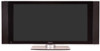
... radios and televisions, use shielded cables and connectors for this equipment does cause harmful interference to provide reasonable protection against harmful interference in a particular installation. Product Name: Plasma Display System (Plasma Display) (Media Receiver) Model Number: PDP-5050HD PDP-4350HD (PDP-505PU) (PDP-435PU) (PDP-AR05U) (PDP-AR05U) PDP-5045HD PDP-4345HD (PDP-504PU) (PDP-434PU) (PDP-R05U) (PDP-R05U) Product Category: Class B Personal Computers & Peripherals Responsible Party Name: PIONEER ELECTRONICS (USA), INC., Customer Support Div. BOX 1760...
... radios and televisions, use shielded cables and connectors for this equipment does cause harmful interference to provide reasonable protection against harmful interference in a particular installation. Product Name: Plasma Display System (Plasma Display) (Media Receiver) Model Number: PDP-5050HD PDP-4350HD (PDP-505PU) (PDP-435PU) (PDP-AR05U) (PDP-AR05U) PDP-5045HD PDP-4345HD (PDP-504PU) (PDP-434PU) (PDP-R05U) (PDP-R05U) Product Category: Class B Personal Computers & Peripherals Responsible Party Name: PIONEER ELECTRONICS (USA), INC., Customer Support Div. BOX 1760...
Owner's Manual
Page 4
.../UHF antennas 21 Switching between antenna A and B 22 Inserting the cable card 22 Connecting the power cord 23 07 Basic Operations Turning on the power (Standby 24 Turning off the power (Standby 24 Watching TV channels 25 Selecting the antenna 25 Changing channels 25 Changing the volume and sound 26 Viewing a channel banner 26 Using the POD service 27 Changing the language 27 Setting MTS/SAP mode 27 Using the multiscreen functions 28 Splitting the screen 28 Freezing images 29 08 Menu Setup Menu...
.../UHF antennas 21 Switching between antenna A and B 22 Inserting the cable card 22 Connecting the power cord 23 07 Basic Operations Turning on the power (Standby 24 Turning off the power (Standby 24 Watching TV channels 25 Selecting the antenna 25 Changing channels 25 Changing the volume and sound 26 Viewing a channel banner 26 Using the POD service 27 Changing the language 27 Setting MTS/SAP mode 27 Using the multiscreen functions 28 Splitting the screen 28 Freezing images 29 08 Menu Setup Menu...
Owner's Manual
Page 5
... mode only 45 Adjusting image positions and clock manually (PC mode only 45 Selecting a screen size 46 Changing the brightness at both sides of the screen (Side Mask 47 Language setting 47 11 Timer Presetting Presetting TV programs using the timer 48 Priority rules for overlapped presettings 49 12 Enjoying through External Equipment Watching a DVD image 50 Connecting a DVD player 50 Displaying a DVD image 50 Watching a VCR image 50 Connecting a VCR 50 Displaying a VCR image 50 Using HDMI Input 51 Connecting HDMI...
... mode only 45 Adjusting image positions and clock manually (PC mode only 45 Selecting a screen size 46 Changing the brightness at both sides of the screen (Side Mask 47 Language setting 47 11 Timer Presetting Presetting TV programs using the timer 48 Priority rules for overlapped presettings 49 12 Enjoying through External Equipment Watching a DVD image 50 Connecting a DVD player 50 Displaying a DVD image 50 Watching a VCR image 50 Connecting a VCR 50 Displaying a VCR image 50 Using HDMI Input 51 Connecting HDMI...
Owner's Manual
Page 6
... by using only parts and accessories designed by using a vacuum cleaner set to its use of time, when using the still picture mode from a TV, VCR, DVD player or any other than 2 hours at a time. • After playing a game, or displaying a PC image or any still image, it is best to view a normal moving pictures (e.g. Plasma Display Systems are not blocked. Typical effects and characteristics of vibration or accidental movement. 01 Important User...
... by using only parts and accessories designed by using a vacuum cleaner set to its use of time, when using the still picture mode from a TV, VCR, DVD player or any other than 2 hours at a time. • After playing a game, or displaying a PC image or any still image, it is best to view a normal moving pictures (e.g. Plasma Display Systems are not blocked. Typical effects and characteristics of vibration or accidental movement. 01 Important User...

Owner's Manual
Page 8
... and performance as described in case the plasma Display breaks. 14. Replacement parts-In case the product needs replacement parts, make sure that the service person uses replacement parts specified by broken glass pieces in the operating instructions. Use of time. Wall or ceiling mounting-When mounting the product on safety. Unplug the power cord from the AC outlet before installing the speakers. 23. The screen may be injured by the manufacturer...
... and performance as described in case the plasma Display breaks. 14. Replacement parts-In case the product needs replacement parts, make sure that the service person uses replacement parts specified by broken glass pieces in the operating instructions. Use of time. Wall or ceiling mounting-When mounting the product on safety. Unplug the power cord from the AC outlet before installing the speakers. 23. The screen may be injured by the manufacturer...

Owner's Manual
Page 22
... the remote control unit. • While watching a broadcast, press ANT to view the image received from the Cable Converter. This service presents various types of useful information, using HTML text. 1 Confirm that the ANTENNA/CABLE A IN terminal has been connected with the coaxial cable from the other antenna. • Pressing ANT while watching in the 2-screen mode (TV image and video image) with TV selected will display the TV image of...
... the remote control unit. • While watching a broadcast, press ANT to view the image received from the Cable Converter. This service presents various types of useful information, using HTML text. 1 Confirm that the ANTENNA/CABLE A IN terminal has been connected with the coaxial cable from the other antenna. • Pressing ANT while watching in the 2-screen mode (TV image and video image) with TV selected will display the TV image of...

Owner's Manual
Page 23
Plasma Display (rear view) English Power cord Media Receiver (rear view) IN OUT VCR CONTROL CONTROL IN ANTENNA B ANTENNA/ CABLE A IN Cable CARD S-VIDEO INPUT 2 INPUT 2 VIDEO R-AUDIO-L DIGITAL OUT OPTICAL (TS) S400 VIDEO INPUT 1 COMPONENT VIDEO R-AUDIO-L Y CB/PB CR/PR SERVICE ONLY OUT MONITOR OUT S-VIDEO VIDEO R-AUDIO-L S-VIDEO R-AUDIO-L IINNPPUUTT 33 Y CB/PB CR/PR INPUT 1 INPUT 3 HDMI ACACINILNET BLACK WHITE SYSTEM CABLE Noise filter Partially eliminates noise caused by the power source. • Use only the supplied power cord. • Be sure to use the ...
Plasma Display (rear view) English Power cord Media Receiver (rear view) IN OUT VCR CONTROL CONTROL IN ANTENNA B ANTENNA/ CABLE A IN Cable CARD S-VIDEO INPUT 2 INPUT 2 VIDEO R-AUDIO-L DIGITAL OUT OPTICAL (TS) S400 VIDEO INPUT 1 COMPONENT VIDEO R-AUDIO-L Y CB/PB CR/PR SERVICE ONLY OUT MONITOR OUT S-VIDEO VIDEO R-AUDIO-L S-VIDEO R-AUDIO-L IINNPPUUTT 33 Y CB/PB CR/PR INPUT 1 INPUT 3 HDMI ACACINILNET BLACK WHITE SYSTEM CABLE Noise filter Partially eliminates noise caused by the power source. • Use only the supplied power cord. • Be sure to use the ...

Owner's Manual
Page 24
... mode and the image on the Plasma Display and remove the power cord from the power outlet. This allows the system to automatically receive digital TV program information in the standby mode. Flashing Power to use this system for a long period of time, press POWER on the screen disappears. • Both STANDBY indicators light up green. • In this manual, "system" means the Plasma Display Panel and Media Receiver. STANDBY/ ON button Media Receiver POWER REC DATA ON STANDBY TIMER ACQUISITION STANDBY indicator POWER ON indicator POWER button Plasma Display/Media Receiver...
... mode and the image on the Plasma Display and remove the power cord from the power outlet. This allows the system to automatically receive digital TV program information in the standby mode. Flashing Power to use this system for a long period of time, press POWER on the screen disappears. • Both STANDBY indicators light up green. • In this manual, "system" means the Plasma Display Panel and Media Receiver. STANDBY/ ON button Media Receiver POWER REC DATA ON STANDBY TIMER ACQUISITION STANDBY indicator POWER ON indicator POWER button Plasma Display/Media Receiver...

Owner's Manual
Page 27
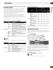
... cable TV channels. • When stereo sound is difficult to view the POD display. • If you have enabled data acquisition using the MTS button, the display changes depending on the remote control unit. • Conventional TV channels in this case, sound is determined by the video source. Changing the language If you have selected a digital TV program that are received through language setting is available when the channel or program is changed...
... cable TV channels. • When stereo sound is difficult to view the POD display. • If you have enabled data acquisition using the MTS button, the display changes depending on the remote control unit. • Conventional TV channels in this case, sound is determined by the video source. Changing the language If you have selected a digital TV program that are received through language setting is available when the channel or program is changed...
Owner's Manual
Page 33
... programs, VCR or DVD contents. Use the following procedure to watch a program (or content) blocked by parents, the Plasma Display shows nothing but a message. When an attempt is made to change the password. 1 Press HOME MENU. 2 Select "Tuner Setup". ( / then ENTER) 3 Select "Parental Control". ( / then ENTER) 4 Select "Password". ( / then ENTER) 5 Select "Change Password". ( / then ENTER) Parental Control Password Password Change Password Clear Password xxxxxxxxxxxxxxxxxxxxx xxxxxxxxxxxxxxxxxxxxx xxxxxxxxxxxxxxxxxxxxx Home Menu Exit 6 Enter the current 4-digit password, using buttons...
... programs, VCR or DVD contents. Use the following procedure to watch a program (or content) blocked by parents, the Plasma Display shows nothing but a message. When an attempt is made to change the password. 1 Press HOME MENU. 2 Select "Tuner Setup". ( / then ENTER) 3 Select "Parental Control". ( / then ENTER) 4 Select "Password". ( / then ENTER) 5 Select "Change Password". ( / then ENTER) Parental Control Password Password Change Password Clear Password xxxxxxxxxxxxxxxxxxxxx xxxxxxxxxxxxxxxxxxxxx xxxxxxxxxxxxxxxxxxxxx Home Menu Exit 6 Enter the current 4-digit password, using buttons...

Owner's Manual
Page 50
... source using the INPUT buttons on the remote control (page 14) or the INPUT button on the Plasma Display. • To protect all equipment, always turn off the system before connecting to the relevant instruction manual (DVD player, personal computer, etc.) carefully before making connections. Media Receiver (rear view) IN OUT VCR CONTROL CONTROL IN ANTENNA B ANTENNA/ CABLE A IN Cable CARD S-VIDEO INPUT 2 VIDEO R-AUDIO-L DIGITAL OUT OPTICAL (TS) S400 VIDEO INPUT 1 COMPONENT VIDEO R-AUDIO-L Y CB/PB CR/PR SERVICE ONLY OUT MONITOR OUT S-VIDEO VIDEO R-AUDIO-L S-VIDEO R-AUDIO...
... source using the INPUT buttons on the remote control (page 14) or the INPUT button on the Plasma Display. • To protect all equipment, always turn off the system before connecting to the relevant instruction manual (DVD player, personal computer, etc.) carefully before making connections. Media Receiver (rear view) IN OUT VCR CONTROL CONTROL IN ANTENNA B ANTENNA/ CABLE A IN Cable CARD S-VIDEO INPUT 2 VIDEO R-AUDIO-L DIGITAL OUT OPTICAL (TS) S400 VIDEO INPUT 1 COMPONENT VIDEO R-AUDIO-L Y CB/PB CR/PR SERVICE ONLY OUT MONITOR OUT S-VIDEO VIDEO R-AUDIO-L S-VIDEO R-AUDIO...

Owner's Manual
Page 51
... and specify the types of these signals, see the operation manual that results in natural color. • If no image appears, specify another digital video signal type. • For the digital video signal types to be input. Before starting the menu, press INPUT 1 (or INPUT 3) on the remote control unit or press INPUT on the Plasma Display to which digital video and audio signals can be received from the connected equipment. Item Description Auto Automatically identifies input digital video (factory default) signals.
... and specify the types of these signals, see the operation manual that results in natural color. • If no image appears, specify another digital video signal type. • For the digital video signal types to be input. Before starting the menu, press INPUT 1 (or INPUT 3) on the remote control unit or press INPUT on the Plasma Display to which digital video and audio signals can be received from the connected equipment. Item Description Auto Automatically identifies input digital video (factory default) signals.

Owner's Manual
Page 52
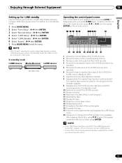
... watching camcorder images Connecting a game console or camcorder Use the INPUT 4 terminals to select INPUT4. Connect the VCR controller to the MONITOR OUT terminals on the Plasma Display to connect a game console, camcorder and other audiovisual equipment. Component Video cable (commercially available) Game console/Camcorder 52 En Digital Accepts digital audio signals. Recording digital TV programs using the supplied VCR controller. Analog Accepts analog audio signals. 6 Press HOME MENU to exit the menu. • If no sound is to...
... watching camcorder images Connecting a game console or camcorder Use the INPUT 4 terminals to select INPUT4. Connect the VCR controller to the MONITOR OUT terminals on the Plasma Display to connect a game console, camcorder and other audiovisual equipment. Component Video cable (commercially available) Game console/Camcorder 52 En Digital Accepts digital audio signals. Recording digital TV programs using the supplied VCR controller. Analog Accepts analog audio signals. 6 Press HOME MENU to exit the menu. • If no sound is to...

Owner's Manual
Page 54
...available) To use i.LINK, you need not connect cables to the video and audio terminals. Digital AV equipment compatible with other data in two directions. When connecting a single D-VHS recorder Media Receiver (rear view) CR CONTROL IN ANTENNA/ CABLE A IN Cable CARD S-VIDEO INPUT 2 VIDEO R-AUDIO-L DIGITAL OUT OPTICAL (TS) S400 VIDEO INPUT 1 COMPONENT VIDEO R-AUDIO-L Y CB/PB CR/PR OUT ITOR OUT S-VIDEO VIDEO R-AUDIO-L S-VIDEO R-AUDIO-L INPUT 3 Y CB/PB CR/PR INPUT 1 IN HDMI (The function and performance are connectable? Connecting D-VHS recorders Use the i.LINK...
...available) To use i.LINK, you need not connect cables to the video and audio terminals. Digital AV equipment compatible with other data in two directions. When connecting a single D-VHS recorder Media Receiver (rear view) CR CONTROL IN ANTENNA/ CABLE A IN Cable CARD S-VIDEO INPUT 2 VIDEO R-AUDIO-L DIGITAL OUT OPTICAL (TS) S400 VIDEO INPUT 1 COMPONENT VIDEO R-AUDIO-L Y CB/PB CR/PR OUT ITOR OUT S-VIDEO VIDEO R-AUDIO-L S-VIDEO R-AUDIO-L INPUT 3 Y CB/PB CR/PR INPUT 1 IN HDMI (The function and performance are connectable? Connecting D-VHS recorders Use the i.LINK...

Owner's Manual
Page 55
... recorder Media Receiver POWER REC DATA ON STANDBY TIMER ACQUISITION D-VHS recorder Displaying a D-VHS image To watch a D-VHS image, press i.LINK on the remote control unit or press INPUT on the Plasma Display to control through i.LINK can record only digital TV programs. Using i.LINK, those recorders cannot record conventional TV channels nor contents coming from external input sources. • This system can be simultaneously connected with equipment that does not support the DTCP...
... recorder Media Receiver POWER REC DATA ON STANDBY TIMER ACQUISITION D-VHS recorder Displaying a D-VHS image To watch a D-VHS image, press i.LINK on the remote control unit or press INPUT on the Plasma Display to control through i.LINK can record only digital TV programs. Using i.LINK, those recorders cannot record conventional TV channels nor contents coming from external input sources. • This system can be simultaneously connected with equipment that does not support the DTCP...
Owner's Manual
Page 57
... control panel screen and displays the i.LINK Setup menu. 20 Allows you cannot execute control. 57 En If this button, press / to select the desired model from the list, and then press ENTER. • If no display for control, you to change the D-VHS recorder to be operated. the i.LINK circuits are connected." After pressing this is in the standby mode; In standby mode i.LINK device Media Receiver i.LINK device POWER...
... control panel screen and displays the i.LINK Setup menu. 20 Allows you cannot execute control. 57 En If this button, press / to select the desired model from the list, and then press ENTER. • If no display for control, you to change the D-VHS recorder to be operated. the i.LINK circuits are connected." After pressing this is in the standby mode; In standby mode i.LINK device Media Receiver i.LINK device POWER...
Owner's Manual
Page 59
... connect the VCR controller to exit the menu. . • Even if you have mistakenly connected it faces the VCR. Media Receiver (rear view) IN OUT VCR CONTROL CONTROL IN ANTENNA B ANTENNA/ CABLE A IN Cable CARD S-VIDEO INPUT 2 VIDEO R-AUDIO-L DIGITAL O OPTICA (TS) S400 VIDEO INPUT 1 COMPON R-AUDIO-L Y CB/ SERVICE ONLY OUT MONITOR OUT S-VIDEO VIDEO R-AUDIO-L S-VIDEO R-AUDIO-L IINNPUTT 33 Y CB/ (Once you correctly specify the manufacture of the recording equipment, control of the Media Receiver. When the specified time comes, the system in recording standby...
... connect the VCR controller to exit the menu. . • Even if you have mistakenly connected it faces the VCR. Media Receiver (rear view) IN OUT VCR CONTROL CONTROL IN ANTENNA B ANTENNA/ CABLE A IN Cable CARD S-VIDEO INPUT 2 VIDEO R-AUDIO-L DIGITAL O OPTICA (TS) S400 VIDEO INPUT 1 COMPON R-AUDIO-L Y CB/ SERVICE ONLY OUT MONITOR OUT S-VIDEO VIDEO R-AUDIO-L S-VIDEO R-AUDIO-L IINNPUTT 33 Y CB/ (Once you correctly specify the manufacture of the recording equipment, control of the Media Receiver. When the specified time comes, the system in recording standby...

Owner's Manual
Page 61
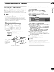
... instruction manual that the power is temporarily minimized. Media Receiver (rear view) IN OUT VCR CONTROL CONTROL IN ANTENNA B ANTENNA/ CABLE A IN Cable CARD S-VIDEO INPUT 2 VIDEO R-AUDIO-L DIGITAL OUT OPTICAL (TS) S400 VIDEO INPUT 1 COMPONENT VIDEO R-AUDIO-L Y CB/PB CR/PR SERVICE ONLY OUT MONITOR OUT S-VIDEO VIDEO R-AUDIO-L S-VIDEO R-AUDIO-L IINNPUTT 33 Y CB/PB CR/PR INPUT 1 INPUT 3 HDMI IN OUT CONTROL • Make sure that came with mini plugs (no resistance). 61 En About SR+ The CONTROL OUT terminal on the Plasma Display when operating the connected...
... instruction manual that the power is temporarily minimized. Media Receiver (rear view) IN OUT VCR CONTROL CONTROL IN ANTENNA B ANTENNA/ CABLE A IN Cable CARD S-VIDEO INPUT 2 VIDEO R-AUDIO-L DIGITAL OUT OPTICAL (TS) S400 VIDEO INPUT 1 COMPONENT VIDEO R-AUDIO-L Y CB/PB CR/PR SERVICE ONLY OUT MONITOR OUT S-VIDEO VIDEO R-AUDIO-L S-VIDEO R-AUDIO-L IINNPUTT 33 Y CB/PB CR/PR INPUT 1 INPUT 3 HDMI IN OUT CONTROL • Make sure that came with mini plugs (no resistance). 61 En About SR+ The CONTROL OUT terminal on the Plasma Display when operating the connected...
Owner's Manual
Page 69
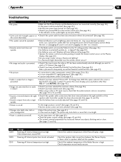
... the Plasma Display Is there a short in after first turning the power of the Media Receiver is presented. • Check if the input source for Energy Save. The picture may cause improper operation. Check if the ambient temperature of the Plasma Display and the Media Receiver, or unplugging the power cord and re-plugging it in speaker cable?and the speakers. Internal temperature too high. To restore the screen display, press...
... the Plasma Display Is there a short in after first turning the power of the Media Receiver is presented. • Check if the input source for Energy Save. The picture may cause improper operation. Check if the ambient temperature of the Plasma Display and the Media Receiver, or unplugging the power cord and re-plugging it in speaker cable?and the speakers. Internal temperature too high. To restore the screen display, press...
Owner's Manual
Page 71
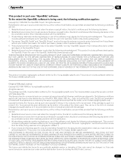
...parts of conditions and the following notification applies: Copyright (c) 1998-2004 The OpenSSL Project. If you must display the following disclaimer. 2. The licence and distribution terms for commercial and non-commercial use of this package is free for any Windows specific code...software written by the OpenSSL Project for use in a product, Eric Young should be given attribution as the following disclaimer in their names without prior written permission of a textual message at program startup or in source and binary forms, with this code... OR SERVICES; LOSS OF USE, DATA...
...parts of conditions and the following notification applies: Copyright (c) 1998-2004 The OpenSSL Project. If you must display the following disclaimer. 2. The licence and distribution terms for commercial and non-commercial use of this package is free for any Windows specific code...software written by the OpenSSL Project for use in a product, Eric Young should be given attribution as the following disclaimer in their names without prior written permission of a textual message at program startup or in source and binary forms, with this code... OR SERVICES; LOSS OF USE, DATA...


