

User Manual
Page 2
... wheel weights or counterweights to improve stability. • Use extra care with manufacturer's recommended parts, when necessary. • Mower blades are often attracted to the off blades when not mowing. machine and the mowing activity. These operators should evaluate their proper... extra caution. Never remove gas cap or add fuel with safe machine operation. • Useextracarewhenloadingorunloadingthemachineinto • Never allow the mower deck to loss-of other objects that you last saw them. • Stop engine before mowing. Allow machine to operate ...
... wheel weights or counterweights to improve stability. • Use extra care with manufacturer's recommended parts, when necessary. • Mower blades are often attracted to the off blades when not mowing. machine and the mowing activity. These operators should evaluate their proper... extra caution. Never remove gas cap or add fuel with safe machine operation. • Useextracarewhenloadingorunloadingthemachineinto • Never allow the mower deck to loss-of other objects that you last saw them. • Stop engine before mowing. Allow machine to operate ...

User Manual
Page 3
... under the watchful care of your tractor. Use common sense when towing. Always look behind before mowing. SAFETY RULES Safe Operation Practices for Ride-On Mowers • Be sure the area is dangerous. Stop machine if anyone enters the area. • Never carry passengers or children even with specifications of the...
... under the watchful care of your tractor. Use common sense when towing. Always look behind before mowing. SAFETY RULES Safe Operation Practices for Ride-On Mowers • Be sure the area is dangerous. Stop machine if anyone enters the area. • Never carry passengers or children even with specifications of the...

User Manual
Page 8
...manual). • Store mulcher blades and mulcher plate in the Service and Adjustments section of this manual. TO SET UP YOUR MOWER FOR MULCHING • Remove high performance blades and install mulcher blades, (see BLADE REMOVAL in "PRODUCT SPECIFICATIONS" section of this..." in the CUSTOMER RESPONSABILITY section of this manual). ASSEMBLY IMPORTANT: FOR SHIPPING PURPOSES, THE MULCHER PLATE WAS PREATTACHED TO YOUR MOWER. YOUR MOWER CAME FACTORY EQUIPPED WITH HIGH PERFORMANCE BLADES, WHICH ARE THE BEST BLADES FOR BAGGING AND DISCHARGING. DEFLECTOR SHIELD MULCHER PLATE LATCH HOOKS...
...manual). • Store mulcher blades and mulcher plate in the Service and Adjustments section of this manual. TO SET UP YOUR MOWER FOR MULCHING • Remove high performance blades and install mulcher blades, (see BLADE REMOVAL in "PRODUCT SPECIFICATIONS" section of this..." in the CUSTOMER RESPONSABILITY section of this manual). ASSEMBLY IMPORTANT: FOR SHIPPING PURPOSES, THE MULCHER PLATE WAS PREATTACHED TO YOUR MOWER. YOUR MOWER CAME FACTORY EQUIPPED WITH HIGH PERFORMANCE BLADES, WHICH ARE THE BEST BLADES FOR BAGGING AND DISCHARGING. DEFLECTOR SHIELD MULCHER PLATE LATCH HOOKS...

User Manual
Page 9
.... BATTERY CAUTION OR WARNING REVERSE FORWARD FAST SLOW ENGINE ON ENGINE OFF OIL PRESSURE CLUTCH LIGHTS ON OVER TEMP LIGHT FUEL CHOKE MOWER HEIGHT DIFFERENTIAL PARKING BRAKE LOCK LOCKED UNLOCKED MOWER LIFT REVERSE NEUTRAL HIGH LOW P PARKING BRAKE 15 15 15 ATTACHMENT ATTACHMENT CLUTCH ENGAGED CLUTCH DISENGAGED KEEP AREA CLEAR SLOPE HAZARDS...
.... BATTERY CAUTION OR WARNING REVERSE FORWARD FAST SLOW ENGINE ON ENGINE OFF OIL PRESSURE CLUTCH LIGHTS ON OVER TEMP LIGHT FUEL CHOKE MOWER HEIGHT DIFFERENTIAL PARKING BRAKE LOCK LOCKED UNLOCKED MOWER LIFT REVERSE NEUTRAL HIGH LOW P PARKING BRAKE 15 15 15 ATTACHMENT ATTACHMENT CLUTCH ENGAGED CLUTCH DISENGAGED KEEP AREA CLEAR SLOPE HAZARDS...
User Manual
Page 10
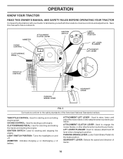
THROTTLE CONTROL: Used for starting the engine. ATTACHMENT CLUTCH LEVER: Used to engage the mower blades, or other attachments mounted to your tractor. CLUTCH/BRAKE PEDAL: Used for starting a cold engine. PARKING BRAKE LEVER: Locks Clutch/Brake Pedal ... Selects the speed and direction of various controls and adjustments. LIFT LEVER PLUNGER: Used to your tractor. Used to raise, lower, and adjust the mower deck or other attachments mounted to release attachment lift lever when changing its position. CHOKE CONTROL: Used for future reference. Save this manual for starting...
THROTTLE CONTROL: Used for starting the engine. ATTACHMENT CLUTCH LEVER: Used to engage the mower blades, or other attachments mounted to your tractor. CLUTCH/BRAKE PEDAL: Used for starting a cold engine. PARKING BRAKE LEVER: Locks Clutch/Brake Pedal ... Selects the speed and direction of various controls and adjustments. LIFT LEVER PLUNGER: Used to your tractor. Used to raise, lower, and adjust the mower deck or other attachments mounted to release attachment lift lever when changing its position. CHOKE CONTROL: Used for future reference. Save this manual for starting...
User Manual
Page 11
...clutch/brake pedal. CLUTCH/BRAKE PEDAL "DRIVE" POSITION PARKING BRAKE "DISENGAGED" POSITION GEAR SHIFT LEVER FIG. 6 STOPPING (See Fig. 6) MOWER BLADES - • To stop ground drive, depress clutch/brake pedal into cutting height. Always wear safety glasses or eye shields while ...operating your tractor or performing any adjustments or repairs. to 4". mance. TO ADJUST MOWER CUTTING HEIGHT (See Fig. 6) GROUND DRIVE - For healthier and better looking lawns, mow often and after moderate growth. The position...
...clutch/brake pedal. CLUTCH/BRAKE PEDAL "DRIVE" POSITION PARKING BRAKE "DISENGAGED" POSITION GEAR SHIFT LEVER FIG. 6 STOPPING (See Fig. 6) MOWER BLADES - • To stop ground drive, depress clutch/brake pedal into cutting height. Always wear safety glasses or eye shields while ...operating your tractor or performing any adjustments or repairs. to 4". mance. TO ADJUST MOWER CUTTING HEIGHT (See Fig. 6) GROUND DRIVE - For healthier and better looking lawns, mow often and after moderate growth. The position...

User Manual
Page 12
... prevent scalping in place. Use common sense when towing. NOTE:Adjust gauge wheels with tractor on a flat level surface. • Adjust mower to leave the seat with an operator presence sensing switch. Any attempt by the operator to desired cutting height (See "TO ADJUST...roll slightly as you have allowed room for opposite side installing gauge wheel in desired height of cut . • Start mower blades by engaging attachment clutch control. • TO STOP MOWER BLADES - Be sure you restart movement. • To restart movement, slowly release parking brake and clutch/brake pedal. &#...
... prevent scalping in place. Use common sense when towing. NOTE:Adjust gauge wheels with tractor on a flat level surface. • Adjust mower to leave the seat with an operator presence sensing switch. Any attempt by the operator to desired cutting height (See "TO ADJUST...roll slightly as you have allowed room for opposite side installing gauge wheel in desired height of cut . • Start mower blades by engaging attachment clutch control. • TO STOP MOWER BLADES - Be sure you restart movement. • To restart movement, slowly release parking brake and clutch/brake pedal. &#...

User Manual
Page 14
... to dry before mowing. • Always operate engine at full throttle when mowing to assure better mowing performance and proper discharge of mower should be mulched a second time to provide nutrients for best mowing performance. Also, the mulched grass will disperse into the grass and... not be noticed. This will plug mower and leave undesirable clumps. Always mulch with the mulching action. Wet grass tends to form clumps and interferes with your highest engine (blade...
... to dry before mowing. • Always operate engine at full throttle when mowing to assure better mowing performance and proper discharge of mower should be mulched a second time to provide nutrients for best mowing performance. Also, the mulched grass will disperse into the grass and... not be noticed. This will plug mower and leave undesirable clumps. Always mulch with the mulching action. Wet grass tends to form clumps and interferes with your highest engine (blade...
User Manual
Page 15
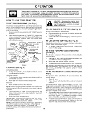
... IN DATES AS YOU COMPLETE REGULAR SERVICE Check Brake Operation Check Tire Pressure Check Operator Presence and T Interlock Systems R Check for Loose Fasteners A Sharpen/Replace Mower Blades C T Lubrication Chart 0 Check Battery Level R Clean Battery and Terminals Check Transaxle Cooling Check V-Belts BEFOREEEVAECRHYU8ESVHEEORUYRS2E5VHEROYUR5E0SVEHROYUR1E0SV0EHROYUBSREESFAOSROEN STORAGE SERVICE DATES 5 3 4 Check Engine Oil Level Change Engine...
... IN DATES AS YOU COMPLETE REGULAR SERVICE Check Brake Operation Check Tire Pressure Check Operator Presence and T Interlock Systems R Check for Loose Fasteners A Sharpen/Replace Mower Blades C T Lubrication Chart 0 Check Battery Level R Clean Battery and Terminals Check Transaxle Cooling Check V-Belts BEFOREEEVAECRHYU8ESVHEEORUYRS2E5VHEROYUR5E0SVEHROYUR1E0SV0EHROYUBSREESFAOSROEN STORAGE SERVICE DATES 5 3 4 Check Engine Oil Level Change Engine...

User Manual
Page 16
... the operator to leave the seat without first setting the parking brake should shut off the engine. • The attachment clutch should be taken to mower and engine. • The blade can harm rubber. • Avoid stumps, stones, deep ruts, sharp objects and other hazards that may cause tire ...damage. BLADE CARE For best results mower blades must be sharpened with balancer.) NOTE: Do not use . Lbs. but are working properly. If either end of the center hole may be ...
... the operator to leave the seat without first setting the parking brake should shut off the engine. • The attachment clutch should be taken to mower and engine. • The blade can harm rubber. • Avoid stumps, stones, deep ruts, sharp objects and other hazards that may cause tire ...damage. BLADE CARE For best results mower blades must be sharpened with balancer.) NOTE: Do not use . Lbs. but are working properly. If either end of the center hole may be ...

User Manual
Page 19
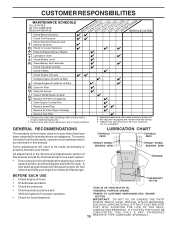
...ENGINE PULLEY FRONT LINK RETAINER SPRINGS (BOTH SIDES) HOUSING GUIDE LARGE RETAINER SPRING BRACKET FIG. 16 19 DEFLECTOR SHIELD TRACTOR TO REMOVE MOWER (See Fig. 16) Mower will be easier to remove from the right side of tractor. • Lower lift lever to its lowest position. • ... to right side of tractor. • Place attachment clutch in contact with large retainer spring. • Install belt onto engine pulley. TO INSTALL MOWER (See Fig. 16) • Raise attachment lift lever to chassis bracket and secure with retainer spring. • Push clutch cable housing guide into...
...ENGINE PULLEY FRONT LINK RETAINER SPRINGS (BOTH SIDES) HOUSING GUIDE LARGE RETAINER SPRING BRACKET FIG. 16 19 DEFLECTOR SHIELD TRACTOR TO REMOVE MOWER (See Fig. 16) Mower will be easier to remove from the right side of tractor. • Lower lift lever to its lowest position. • ... to right side of tractor. • Place attachment clutch in contact with large retainer spring. • Install belt onto engine pulley. TO INSTALL MOWER (See Fig. 16) • Raise attachment lift lever to chassis bracket and secure with retainer spring. • Push clutch cable housing guide into...

User Manual
Page 20
... • At the midpoint of both front links an equal number of turns. NOTE: Each full turn of adjustment nut will not properly adjust your mower. Tighten nut "E" on both front links. • Recheck side-to 1/2" lower at front than rear, tighten nut "F" against trunnion on both front ... so that the front is approximately 1/8" to 1/2" lower than rear, tighten nuts "F" against trunnion on both front links. BELT REMOVAL • Remove mower from mower. If tires are not equal in length. • When distance "D" is 1/8" to ground. The two front links must remain equal in length, ...
... • At the midpoint of both front links an equal number of turns. NOTE: Each full turn of adjustment nut will not properly adjust your mower. Tighten nut "E" on both front links. • Recheck side-to 1/2" lower at front than rear, tighten nut "F" against trunnion on both front ... so that the front is approximately 1/8" to 1/2" lower than rear, tighten nuts "F" against trunnion on both front links. BELT REMOVAL • Remove mower from mower. If tires are not equal in length. • When distance "D" is 1/8" to ground. The two front links must remain equal in length, ...
User Manual
Page 21
...the Assembly section of manual). however, if adjustment is needed to get to the lowest position. NOTE: When the tractor rear wheels move mower deck height to adjustment bolt, move freely, the transaxle is in neutral. • Loosen adjustment bolt in the neutral (N) position. ...jam nut and turn nut "A" until distance becomes 1-1/2". BELT REMOVAL - • Remove mower (See "TO REMOVE MOWER" in this section of all belt guides and keepers. • Install mower (See "TO INSTALL MOWER" in this section of this manual. Remove belt upwards from stationary idler and clutching idler...
...the Assembly section of manual). however, if adjustment is needed to get to the lowest position. NOTE: When the tractor rear wheels move mower deck height to adjustment bolt, move freely, the transaxle is in neutral. • Loosen adjustment bolt in the neutral (N) position. ...jam nut and turn nut "A" until distance becomes 1-1/2". BELT REMOVAL - • Remove mower (See "TO REMOVE MOWER" in this section of all belt guides and keepers. • Install mower (See "TO INSTALL MOWER" in this section of this manual. Remove belt upwards from stationary idler and clutching idler...

User Manual
Page 24
...STORAGE Immediately prepare your tractor for storage at least 10 minutes after adding stabilizer to allow the stabilizer to cool before painting. When mower is to give protection from tractor for storage, do not store battery directly on stabilizer container. Run engine at the end of the... of oil through spark plug hole(s) into cylinder(s). • Turn ignition key to "START" position for damage, breakage and wear. TRACTOR Remove mower from one ounce of this manual. • Be sure that does not retain moisture. Inspect moving parts for a few seconds to gasoline in ...
...STORAGE Immediately prepare your tractor for storage at least 10 minutes after adding stabilizer to allow the stabilizer to cool before painting. When mower is to give protection from tractor for storage, do not store battery directly on stabilizer container. Run engine at the end of the... of oil through spark plug hole(s) into cylinder(s). • Turn ignition key to "START" position for damage, breakage and wear. TRACTOR Remove mower from one ounce of this manual. • Be sure that does not retain moisture. Inspect moving parts for a few seconds to gasoline in ...

User Manual
Page 25
...of adjustment. 15. Recharge or replace battery. 4. Attachment clutch is engaged. 3. Check/replace solenoid or starter. Carburetor out of adjustment. 8. Engine valves out of mower housing. 4. Clean underside of adjustment. 1. Clean and regap or change oil. 6. Connect and tighten spark plug wire. 11. Water in fuel. 10. Check... to start 1. Drain fuel tank and refill with fresh gasoline. 9. Check all wiring. 7. Carburetor out of grass, leaves and trash under mower. 4. Engine will not start . 4. Build-up of adjustment. 10. Replace fuel filter. 8.
...of adjustment. 15. Recharge or replace battery. 4. Attachment clutch is engaged. 3. Check/replace solenoid or starter. Carburetor out of adjustment. 8. Engine valves out of mower housing. 4. Clean underside of adjustment. 1. Clean and regap or change oil. 6. Connect and tighten spark plug wire. 11. Water in fuel. 10. Check... to start 1. Drain fuel tank and refill with fresh gasoline. 9. Check all wiring. 7. Carburetor out of grass, leaves and trash under mower. 4. Engine will not start . 4. Build-up of adjustment. 10. Replace fuel filter. 8.

User Manual
Page 26
...lamp(s). 3. Check/clean all connections. 3. If not corrected, contact an authorized service center/ department. Poor cut - Worn/damaged mower drive belt. 3. Mower deck not level. 5. Improper blades used. 11. Tighten blade bolt. 7. Bulb(s) or lamp(s) burned out. 3. Check ..." when turning engine "OFF" 1. Faulty operator-safety presence control system. 1. Remove obstruction. 2. Wet grass. 4. Clean underside of mower housing. 4. Replace fuse. Replace battery. 2. Place throttle control in "FAST" position. 2. Reinstall blades sharp edge down. 10. Headlight...
...lamp(s). 3. Check/clean all connections. 3. If not corrected, contact an authorized service center/ department. Poor cut - Worn/damaged mower drive belt. 3. Mower deck not level. 5. Improper blades used. 11. Tighten blade bolt. 7. Bulb(s) or lamp(s) burned out. 3. Check ..." when turning engine "OFF" 1. Faulty operator-safety presence control system. 1. Remove obstruction. 2. Wet grass. 4. Clean underside of mower housing. 4. Replace fuse. Replace battery. 2. Place throttle control in "FAST" position. 2. Reinstall blades sharp edge down. 10. Headlight...
User Manual
Page 31
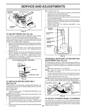
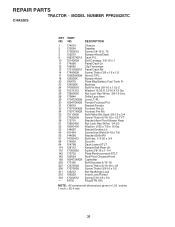
... 179717X428 Footrest Pnt Rh 35 72110606 Bolt Rdhd Sht Sqnk 3/8-16 x 3/4 37 17490508 Screw Thdrol 6/16-18 x 1/2 TYT 38 175710 Bracket Asm Pivot Mower Rear 51 73800400 Nut Lock Hex W/Ins 1/4-20 52 19091416 Washer 9/32 x 7/8 x 16 Ga. 53 144697 Bracjet Grukke Lh 54 161464 Screw Hex Wshd... Screw Thdrol 3/8-16 x 1/2 211 145212 Nut Hexflange Lock 212 156229 Insert Lens Relect 219 17000512 Screw 5/16-18 x 3/4 --- 5479J Plug BTN. MODEL NUMBER PPR2042STC CHASSIS KEY PART NO. inches 1 inch = 25.4 mm 31 NO. Blk NOTE: All component dimensions given in U.S. REPAIR PARTS TRACTOR -
... 179717X428 Footrest Pnt Rh 35 72110606 Bolt Rdhd Sht Sqnk 3/8-16 x 3/4 37 17490508 Screw Thdrol 6/16-18 x 1/2 TYT 38 175710 Bracket Asm Pivot Mower Rear 51 73800400 Nut Lock Hex W/Ins 1/4-20 52 19091416 Washer 9/32 x 7/8 x 16 Ga. 53 144697 Bracjet Grukke Lh 54 161464 Screw Hex Wshd... Screw Thdrol 3/8-16 x 1/2 211 145212 Nut Hexflange Lock 212 156229 Insert Lens Relect 219 17000512 Screw 5/16-18 x 3/4 --- 5479J Plug BTN. MODEL NUMBER PPR2042STC CHASSIS KEY PART NO. inches 1 inch = 25.4 mm 31 NO. Blk NOTE: All component dimensions given in U.S. REPAIR PARTS TRACTOR -
User Manual
Page 33
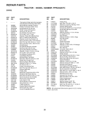
MODEL NUMBER PPR2042STC DRIVE KEY PART NO. DESCRIPTION 63 175410 Pulley Eng 64 71170764 Bolt Hex 7/16-20 x 4 Gr 5 65 10040700 Washer Lock Hvy Hlcl Spr 7/16 66 154778 Keeper Belt Engine 69 145432 Screw Hex Wsh Hi-Lo 1/4-1/2 Unc 70 134683 Guide Belt Mower Drive RH 74 137057 Spacer Split 75 121749X...
MODEL NUMBER PPR2042STC DRIVE KEY PART NO. DESCRIPTION 63 175410 Pulley Eng 64 71170764 Bolt Hex 7/16-20 x 4 Gr 5 65 10040700 Washer Lock Hvy Hlcl Spr 7/16 66 154778 Keeper Belt Engine 69 145432 Screw Hex Wsh Hi-Lo 1/4-1/2 Unc 70 134683 Guide Belt Mower Drive RH 74 137057 Spacer Split 75 121749X...
User Manual
Page 37
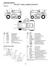
... dimensions given in U.S. MODEL NUMBER PPR2042STC DECALS 2 11 9 16 4 43 10 2 20 1 8 7 5 14 KEY NO. 1 2 3 4 5 7 8 PART NO. 156369 176305 176308 177020 180710 179128 170563 9 172740 10 157140 DESCRIPTION Decal Oper Decal Fender Decal Hood LH Decal Side Panel Logo Decal HP Engine Decal Deck "B" "42" Decal Mower Warn Keep Hand Away Decal...
... dimensions given in U.S. MODEL NUMBER PPR2042STC DECALS 2 11 9 16 4 43 10 2 20 1 8 7 5 14 KEY NO. 1 2 3 4 5 7 8 PART NO. 156369 176305 176308 177020 180710 179128 170563 9 172740 10 157140 DESCRIPTION Decal Oper Decal Fender Decal Hood LH Decal Side Panel Logo Decal HP Engine Decal Deck "B" "42" Decal Mower Warn Keep Hand Away Decal...
User Manual
Page 41
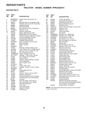
... 3/8-16 119 19121414 Washer 3/8 x 7/8 x 14 Ga. 121 173986 Bracket, Extruded 132 17060612 Screw 3/8-16 x .75 142 165890 Arm Spring Brake Mower 143 157109 Bracket Arm Idler 42" 144 173441 Keeper Belt 42" Clutch Cable 145 173437 Pulley Idler Flat 146 173443 Bolt Carriage Idler 147 131335...Retainer 59 173442 Guard TUV Idler 67 171598 Knob Round KEY PART NO. REPAIR PARTS TRACTOR - NO. Pulley not included) - - 172559 Mower Deck, Complete NOTE: All component dimensions given in U.S. inches 1 inch = 25.4 mm 41 MODEL NUMBER PPR2042STC MOWER DECK KEY PART NO.
... 3/8-16 119 19121414 Washer 3/8 x 7/8 x 14 Ga. 121 173986 Bracket, Extruded 132 17060612 Screw 3/8-16 x .75 142 165890 Arm Spring Brake Mower 143 157109 Bracket Arm Idler 42" 144 173441 Keeper Belt 42" Clutch Cable 145 173437 Pulley Idler Flat 146 173443 Bolt Carriage Idler 147 131335...Retainer 59 173442 Guard TUV Idler 67 171598 Knob Round KEY PART NO. REPAIR PARTS TRACTOR - NO. Pulley not included) - - 172559 Mower Deck, Complete NOTE: All component dimensions given in U.S. inches 1 inch = 25.4 mm 41 MODEL NUMBER PPR2042STC MOWER DECK KEY PART NO.


