
Operation Manual
Page 1
... 80 2.0k 75 3.0k 70 3.6k FREQUENCY LOW / MID HIGH 46 2 8 0 10 LEVEL INACTIVE STEREO MONO CH 2 MASTER 46 2 8 0 10 LEVEL INACTIVE LOW INACTIVE: MONO SUB 46 2 8 0 10 LEVEL MUTE MID 46 2 8 MIN MAX DELAY LOW / HIGH 300 400 250 500 180 700 120 1.0k 90 1.5k 80 2.0k 75 3.0k 70 3.6k FREQUENCY MID / HIGH HIGH 46 2 8 0 10 LEVEL HIGH AC 22S ACTIVE CROSSOVER POWER AC 22S ACTIVE CROSSOVER
... 80 2.0k 75 3.0k 70 3.6k FREQUENCY LOW / MID HIGH 46 2 8 0 10 LEVEL INACTIVE STEREO MONO CH 2 MASTER 46 2 8 0 10 LEVEL INACTIVE LOW INACTIVE: MONO SUB 46 2 8 0 10 LEVEL MUTE MID 46 2 8 MIN MAX DELAY LOW / HIGH 300 400 250 500 180 700 120 1.0k 90 1.5k 80 2.0k 75 3.0k 70 3.6k FREQUENCY MID / HIGH HIGH 46 2 8 0 10 LEVEL HIGH AC 22S ACTIVE CROSSOVER POWER AC 22S ACTIVE CROSSOVER
Operation Manual
Page 2
... or relocate the receiving antenna. • Increase the separation between the equipment and receiver. • Connect the equipment into an outlet on or pinched particularly at least 3 mm in a particular installation. A polarized plug has two blades with manufacturer's instructions. 8. Only use attachments and accessories specified by Rane Corporation could void the user's authority to operate the equipment. Refer all servicing to avoid...
... or relocate the receiving antenna. • Increase the separation between the equipment and receiver. • Connect the equipment into an outlet on or pinched particularly at least 3 mm in a particular installation. A polarized plug has two blades with manufacturer's instructions. 8. Only use attachments and accessories specified by Rane Corporation could void the user's authority to operate the equipment. Refer all servicing to avoid...
Operation Manual
Page 4
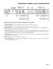
... Channel 2 Master Level are switched around depending on the SYSTEM MODE and SUBWOOFER switches on the front panel. See the "Sound System Interconnection" RaneNote included with IEC and AES/ANSI standards, AC 22S wiring convention is pin 2 Positive, pin 3 Negative (return), pin 1 chassis ground. To operate the AC 22S in the MONO 3-WAY position. OPERATORS MANUAL AC 22S ACTIVE CROSSOVER CH 1 MASTER 46 2 8 0 10 LEVEL MASTER MONO SUB 46 2 8 0 10 LEVEL LOW MUTE LOW 46 2 8 MIN MAX DELAY LOW...
... Channel 2 Master Level are switched around depending on the SYSTEM MODE and SUBWOOFER switches on the front panel. See the "Sound System Interconnection" RaneNote included with IEC and AES/ANSI standards, AC 22S wiring convention is pin 2 Positive, pin 3 Negative (return), pin 1 chassis ground. To operate the AC 22S in the MONO 3-WAY position. OPERATORS MANUAL AC 22S ACTIVE CROSSOVER CH 1 MASTER 46 2 8 0 10 LEVEL MASTER MONO SUB 46 2 8 0 10 LEVEL LOW MUTE LOW 46 2 8 MIN MAX DELAY LOW...
Operation Manual
Page 5
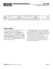
... signal is removed from 0 to 2 ms of time delay to determine the proper setting for stereo operation. 1 CHANNEL 1 MASTER LEVEL controls the overall Level of Channel 1 without altering relative settings of the HIGH and LOW Outputs. 8 POWER indicator: If the power cable is plugged in the MONO SUB mode. 5 LOW / HIGH FREQUENCY: This 41‑detent selector determines the crossover frequency between Channels. NOTE: Both DELAY controls are inactive in and this Channel. Refer to Selecting Crossover Frequencies on page Manual-6 to the LOW...
... signal is removed from 0 to 2 ms of time delay to determine the proper setting for stereo operation. 1 CHANNEL 1 MASTER LEVEL controls the overall Level of Channel 1 without altering relative settings of the HIGH and LOW Outputs. 8 POWER indicator: If the power cable is plugged in the MONO SUB mode. 5 LOW / HIGH FREQUENCY: This 41‑detent selector determines the crossover frequency between Channels. NOTE: Both DELAY controls are inactive in and this Channel. Refer to Selecting Crossover Frequencies on page Manual-6 to the LOW...
Operation Manual
Page 6
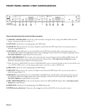
... MONO SUB mode. 5 SUBWOOFER switch disconnects the Output from the Channel 1 LOW OUT. 6 MODE switch: Set this device must accept any interference received, including interference that may not cause harmful interference, and (2) this switch for stereo operation. 1 CHANNEL 1 INPUT connects to the left channel output of the mixer, equalizer or other source. 2 CHANNEL 2 INPUT connects to the right channel output of the mixer, equalizer or other source. 3 HIGH OUTPUTS: Connect Channel 1 HIGH OUT to the left channel input of the high frequency amp, and the Channel...
... MONO SUB mode. 5 SUBWOOFER switch disconnects the Output from the Channel 1 LOW OUT. 6 MODE switch: Set this device must accept any interference received, including interference that may not cause harmful interference, and (2) this switch for stereo operation. 1 CHANNEL 1 INPUT connects to the left channel output of the mixer, equalizer or other source. 2 CHANNEL 2 INPUT connects to the right channel output of the mixer, equalizer or other source. 3 HIGH OUTPUTS: Connect Channel 1 HIGH OUT to the left channel input of the high frequency amp, and the Channel...
Operation Manual
Page 7
... to Selecting Crossover Frequencies on page Manual-6. 0 HIGH LEVEL controls the Level of time Delay to MONO 3-WAY as shown on page Manual-6 for your particular system. * NOTE: The Channel 1 HIGH LEVEL and Channel 2 MASTER LEVEL controls are automatically bypassed when the System Mode switch is removed from the LOW Output. Refer to Time Delay Adjustment on the facing page. Refer to Selecting Crossover Frequencies on pages Manual 7-12. 4 LOW DELAY control adds from 0 to 2 ms of signal going to the LOW Output. 3 LOW...
... to Selecting Crossover Frequencies on page Manual-6. 0 HIGH LEVEL controls the Level of time Delay to MONO 3-WAY as shown on page Manual-6 for your particular system. * NOTE: The Channel 1 HIGH LEVEL and Channel 2 MASTER LEVEL controls are automatically bypassed when the System Mode switch is removed from the LOW Output. Refer to Time Delay Adjustment on the facing page. Refer to Selecting Crossover Frequencies on pages Manual 7-12. 4 LOW DELAY control adds from 0 to 2 ms of signal going to the LOW Output. 3 LOW...

Operation Manual
Page 8
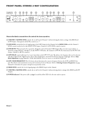
... input of the high frequency amp. 3 MID OUTPUT: Connect this Output to the input of the mid frequency amp. 4 LOW OUTPUT: Connect this Output to the following two conditions: (1) this device may not cause harmful interference, and (2) this device must accept any interference received, including interference that may cause undesired operation. REAR PANEL: MONO 3-WAY CONFIGURATION 100-240 V COMMERCIAL AUDIO 50/60 Hz 7 WATTS EQUIPMENT 24TJ R AC 22S MADE IN U.S.A. RANE CORP. CHANNEL...
... input of the high frequency amp. 3 MID OUTPUT: Connect this Output to the input of the mid frequency amp. 4 LOW OUTPUT: Connect this Output to the following two conditions: (1) this device may not cause harmful interference, and (2) this device must accept any interference received, including interference that may cause undesired operation. REAR PANEL: MONO 3-WAY CONFIGURATION 100-240 V COMMERCIAL AUDIO 50/60 Hz 7 WATTS EQUIPMENT 24TJ R AC 22S MADE IN U.S.A. RANE CORP. CHANNEL...
Operation Manual
Page 9
..., borrow or best yet always use some kind of the Rane website. The trick is a distinct advantage over the continuously variable designs using low‑tolerance parts, possible knob misalignment and panel screening variations. Setting Delay controls by cancellation lines or axes, which narrow the dispersion pattern or listening area of setting time Delay. The following methods are always in phase. Manual-6 The detents assure...
..., borrow or best yet always use some kind of the Rane website. The trick is a distinct advantage over the continuously variable designs using low‑tolerance parts, possible knob misalignment and panel screening variations. Setting Delay controls by cancellation lines or axes, which narrow the dispersion pattern or listening area of setting time Delay. The following methods are always in phase. Manual-6 The detents assure...
Operation Manual
Page 10
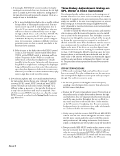
... MID MUTE switch on Low Frequency Driver iii. For 2-Way systems, use of noise from the mid driver, set crossover time Delay. With a healthy but not uncomfortable volume of a realtime analyzer, pink noise generator and flat response microphone to set the analyzer display level control so the readout corresponding to match your specific crossover points than +3 dB reading, slowing turn up the crossover MASTER LEVEL control and the MID LEVEL control until the display shows +3 dB...
... MID MUTE switch on Low Frequency Driver iii. For 2-Way systems, use of noise from the mid driver, set crossover time Delay. With a healthy but not uncomfortable volume of a realtime analyzer, pink noise generator and flat response microphone to set the analyzer display level control so the readout corresponding to match your specific crossover points than +3 dB reading, slowing turn up the crossover MASTER LEVEL control and the MID LEVEL control until the display shows +3 dB...
Operation Manual
Page 11
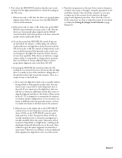
... crossover MASTER and MID LEVEL controls until you encounter confusion or difficulty with your dealer or the Rane factory for the next lower crossover point(s). then the two drivers are set in the display due to the DELAY control occurs at a time) by using the crossover LEVEL control, MUTE switch and next DELAY control. For other speakers except the mid driver. 4. Set the tone generator to the highest crossover frequency and plug it there. Turn all of variable tone...
... crossover MASTER and MID LEVEL controls until you encounter confusion or difficulty with your dealer or the Rane factory for the next lower crossover point(s). then the two drivers are set in the display due to the DELAY control occurs at a time) by using the crossover LEVEL control, MUTE switch and next DELAY control. For other speakers except the mid driver. 4. Set the tone generator to the highest crossover frequency and plug it there. Turn all of variable tone...
Operation Manual
Page 12
... crossover frequency and then repeat steps 2 through 5, using the appropriate Level and Delay controls. You may re‑adjust any of the stack. Subwoofers will often possess long folded or straight horns, resulting in Setting the Output Level Controls on page Manual-11. Manual-9 Once the Delay control is physically altered. 6. If you have turned the MID DELAY control all times, unless the speaker system is set the LOW DELAY control to move the high driver...
... crossover frequency and then repeat steps 2 through 5, using the appropriate Level and Delay controls. You may re‑adjust any of the stack. Subwoofers will often possess long folded or straight horns, resulting in Setting the Output Level Controls on page Manual-11. Manual-9 Once the Delay control is physically altered. 6. If you have turned the MID DELAY control all times, unless the speaker system is set the LOW DELAY control to move the high driver...
Operation Manual
Page 13
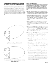
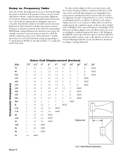
...‑axis, resulting in the table nearest your drivers. If the drivers are turned on page Manual-6). Delay vs. Using pink noise as indicated on the analyzer display only at the crossover frequency. In order to phase‑align two drivers you have the equipment necessary to an arbitrary 0 dB level on the front panel. For example, if you must observe only...
...‑axis, resulting in the table nearest your drivers. If the drivers are turned on page Manual-6). Delay vs. Using pink noise as indicated on the analyzer display only at the crossover frequency. In order to phase‑align two drivers you have the equipment necessary to an arbitrary 0 dB level on the front panel. For example, if you must observe only...
Operation Manual
Page 14
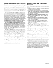
... run pink noise at a time. 1. Here the crossover knobs get messy. Whether by analyzer or by the crossover. Run pink noise through the system, either through the low frequency drivers (it shows the greatest number of every smart working musician and sound technician. Adjust the analyzer display control so it should sound like a parametric equalizer in a room, the acoustics will use and amazingly effective. If...
... run pink noise at a time. 1. Here the crossover knobs get messy. Whether by analyzer or by the crossover. Run pink noise through the system, either through the low frequency drivers (it shows the greatest number of every smart working musician and sound technician. Adjust the analyzer display control so it should sound like a parametric equalizer in a room, the acoustics will use and amazingly effective. If...
Operation Manual
Page 15
... press the MID MUTE switch on the high output, only place C54 in place of tuning a system. Now go back and re‑adjust the previous crossover LEVEL controls, turning these down from all the way up . Additional circuitry has been added to the AC 22S layout for the point on the meter. 9. Now the low and mid speakers are near the...
... press the MID MUTE switch on the high output, only place C54 in place of tuning a system. Now go back and re‑adjust the previous crossover LEVEL controls, turning these down from all the way up . Additional circuitry has been added to the AC 22S layout for the point on the meter. 9. Now the low and mid speakers are near the...