

Product Manual
Page 7
... used in the CompactFlash Memory Card manages interface protocols, data storage and retrieval as well as a standard ATA (IDE) disk drive. Each sector is electrically compatible with a Type II PCMCIA adapter can support as many cards as there are CompactFlash and PCMCIA Type II or III card slots. CompactFlash Memory cards use in 512 byte sectors. CHAPTER 1 Introduction 1.1 General Description SanDisk CompactFlash® Memory Card products provide high capacity solid-state flash memory...
... used in the CompactFlash Memory Card manages interface protocols, data storage and retrieval as well as a standard ATA (IDE) disk drive. Each sector is electrically compatible with a Type II PCMCIA adapter can support as many cards as there are CompactFlash and PCMCIA Type II or III card slots. CompactFlash Memory cards use in 512 byte sectors. CHAPTER 1 Introduction 1.1 General Description SanDisk CompactFlash® Memory Card products provide high capacity solid-state flash memory...

Product Manual
Page 8
... this manual. 1.4 CompactFlash Standard SanDisk CompactFlash Memory cards are fully compatible with the CompactFlash Specification published by the CompactFlash Association. Box 51537 Palo Alto, CA 94303 USA Phone: 415-843-1220 Fax: 415-493-1871 www.compactflash.org 02/07, Rev. 12.0 1-2 © 2007 SanDisk Corporation Introduction SanDisk CompactFlash Card OEM Product Manual 1.2 Features SanDisk CompactFlash Memory cards provide the following system features: • Up to 16 GB of mass storage data...
... this manual. 1.4 CompactFlash Standard SanDisk CompactFlash Memory cards are fully compatible with the CompactFlash Specification published by the CompactFlash Association. Box 51537 Palo Alto, CA 94303 USA Phone: 415-843-1220 Fax: 415-493-1871 www.compactflash.org 02/07, Rev. 12.0 1-2 © 2007 SanDisk Corporation Introduction SanDisk CompactFlash Card OEM Product Manual 1.2 Features SanDisk CompactFlash Memory cards provide the following system features: • Up to 16 GB of mass storage data...

Product Manual
Page 9
SanDisk CompactFlash Card OEM Product Manual Introduction 1.5 PCMCIA Standard SanDisk CompactFlash Memory cards are fully electrically compatible with the PCMCIA specifications listed below: • PCMCIA PC Card Standard, 7.0, February 1999 • PCMCIA PC Card ATA Specification, 7.0, February 1999 These specifications may be ordered from IHS by ANSI. This intelligent (microprocessor) subsystem provides many capabilities not found in magnetic disk drives). • Sophisticated system for error recovery including a powerful...
SanDisk CompactFlash Card OEM Product Manual Introduction 1.5 PCMCIA Standard SanDisk CompactFlash Memory cards are fully electrically compatible with the PCMCIA specifications listed below: • PCMCIA PC Card Standard, 7.0, February 1999 • PCMCIA PC Card ATA Specification, 7.0, February 1999 These specifications may be ordered from IHS by ANSI. This intelligent (microprocessor) subsystem provides many capabilities not found in magnetic disk drives). • Sophisticated system for error recovery including a powerful...

Product Manual
Page 10
.... The CompactFlash Memory Card soft error rate specification is completely transparent to recover the data by using NAND memory. This is extremely important as flash devices are used to maintain backward compatibility with the solid state construction, give SanDisk CompactFlash cards unparalleled reliability 1.7.3 Wear Leveling Wear Leveling is supported as a NOP operation to ensure high data reliability and maximize flash life expectancy. 1.7.4 Using Erase Sector and Write Commands SanDisk CompactFlash Memory cards support the...
.... The CompactFlash Memory Card soft error rate specification is completely transparent to recover the data by using NAND memory. This is extremely important as flash devices are used to maintain backward compatibility with the solid state construction, give SanDisk CompactFlash cards unparalleled reliability 1.7.3 Wear Leveling Wear Leveling is supported as a NOP operation to ensure high data reliability and maximize flash life expectancy. 1.7.4 Using Erase Sector and Write Commands SanDisk CompactFlash Memory cards support the...

Product Manual
Page 11
... Per the PCMCIA specification Section 2.1.1, the host system must be treated as other ATA products may do this if desired, but it will enter sleep mode to follow the ATA protocol of issuing a reset first. In most systems, the CompactFlash Memory Card is accessing it ...is in sleep mode, any action for the 5.00-volt range and less than 15%. SanDisk CompactFlash Card OEM Product Manual Introduction 1.7.5 Automatic Sleep Mode A unique feature of the SanDisk CompactFlash Memory Card is required if the host system applies an input voltage outside the desired voltage by more than...
... Per the PCMCIA specification Section 2.1.1, the host system must be treated as other ATA products may do this if desired, but it will enter sleep mode to follow the ATA protocol of issuing a reset first. In most systems, the CompactFlash Memory Card is accessing it ...is in sleep mode, any action for the 5.00-volt range and less than 15%. SanDisk CompactFlash Card OEM Product Manual Introduction 1.7.5 Automatic Sleep Mode A unique feature of the SanDisk CompactFlash Memory Card is required if the host system applies an input voltage outside the desired voltage by more than...

Product Manual
Page 13
...Product Specifications For all the following specifications, values are typical at ambient temperature and nominal supply voltage unless otherwise stated. 2.1 System Environmental Specifications Table 2-1 contains environmental specifications...supply voltage unless otherwise stated. © 2007 SanDisk Corporation 2-1 Rev. 12.0, 02/07 Table 2-1 Environmental Specifications Temperature Humidity Acoustic Noise Vibration Shock Altitude (...15 G peak to peak maximum 2,000 G maximum 2,000 G maximum 80,000 ft. maximum CompactFlash Extreme III -25° C to 85° C -25° C to 85° C...
...Product Specifications For all the following specifications, values are typical at ambient temperature and nominal supply voltage unless otherwise stated. 2.1 System Environmental Specifications Table 2-1 contains environmental specifications...supply voltage unless otherwise stated. © 2007 SanDisk Corporation 2-1 Rev. 12.0, 02/07 Table 2-1 Environmental Specifications Temperature Humidity Acoustic Noise Vibration Shock Altitude (...15 G peak to peak maximum 2,000 G maximum 2,000 G maximum 80,000 ft. maximum CompactFlash Extreme III -25° C to 85° C -25° C to 85° C...
Product Manual
Page 14
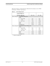
... mA Read/Write Peak 100 mA Memory Subsystema CompactFlash Extreme III Memory Card Sleep Up to 512 MB 300 µ 512 MB to 1.5 GB 600 µ Over 1.5 GB 1 mA Read 75 mA Write 75 mA Read/Write Peak 100 mA a. Table 2-2 Power Requirements DC Input Voltage (Vcc) 100 mV max. Product Specifications SanDisk CompactFlash Card OEM Product Manual Sleep mode currently is specified...
... mA Read/Write Peak 100 mA Memory Subsystema CompactFlash Extreme III Memory Card Sleep Up to 512 MB 300 µ 512 MB to 1.5 GB 600 µ Over 1.5 GB 1 mA Read 75 mA Write 75 mA Read/Write Peak 100 mA a. Table 2-2 Power Requirements DC Input Voltage (Vcc) 100 mV max. Product Specifications SanDisk CompactFlash Card OEM Product Manual Sleep mode currently is specified...

Product Manual
Page 15
...SanDisk CompactFlash Card OEM Product Manual Product Specifications 2.3 System Performance All performance timings assume the CompactFlash Memory Card Series controller is issued by the host to exit sleep mode. © 2007 SanDisk Corporation 2-3 Rev. 12.0, 02/07 Table 2-3 Performance CompactFlash Memory Card Start-up Times Sleep to Write Sleep to Read Reset to Ready Active to Sleep Delay Data Transfer Rate To/From Flash Data... maximum CompactFlash Extreme III Memory Card Start-up Times Sleep to Write Sleep to Read Reset to Ready Data Transfer Rate To/From Flash Data Transfer ...
...SanDisk CompactFlash Card OEM Product Manual Product Specifications 2.3 System Performance All performance timings assume the CompactFlash Memory Card Series controller is issued by the host to exit sleep mode. © 2007 SanDisk Corporation 2-3 Rev. 12.0, 02/07 Table 2-3 Performance CompactFlash Memory Card Start-up Times Sleep to Write Sleep to Read Reset to Ready Active to Sleep Delay Data Transfer Rate To/From Flash Data... maximum CompactFlash Extreme III Memory Card Start-up Times Sleep to Write Sleep to Read Reset to Ready Data Transfer Rate To/From Flash Data Transfer ...

Product Manual
Page 19
... I/O I/O I/O I O - Low active signals have a "-" prefix. Sections 3.3.1 and 3.3.2 define the DC characteristics for all input and output type structures.. Table 3-1 PC Card Memory Mode Pin Assignments Pin No. 1 2 3 4 5 6 7 8 9 10 11 12 13 14 15 16 17 18 19 20 21 22 23 24 25 Signal Name...I3U I1U,OT1 I1U,OT1 I1Z,OZ3 I1Z,OZ3 I1Z,OZ3 Ground © 2007 SanDisk Corporation 3-1 Rev. 12.0, 02/07 CHAPTER 3 Interface Description 3.1 Physical Description The host connects to SanDisk CompactFlash Memory cards using a standard 50-pin connector consisting of two rows of 25 female contacts each on...
... I/O I/O I/O I O - Low active signals have a "-" prefix. Sections 3.3.1 and 3.3.2 define the DC characteristics for all input and output type structures.. Table 3-1 PC Card Memory Mode Pin Assignments Pin No. 1 2 3 4 5 6 7 8 9 10 11 12 13 14 15 16 17 18 19 20 21 22 23 24 25 Signal Name...I3U I1U,OT1 I1U,OT1 I1Z,OZ3 I1Z,OZ3 I1Z,OZ3 Ground © 2007 SanDisk Corporation 3-1 Rev. 12.0, 02/07 CHAPTER 3 Interface Description 3.1 Physical Description The host connects to SanDisk CompactFlash Memory cards using a standard 50-pin connector consisting of two rows of 25 female contacts each on...

Product Manual
Page 22
... lines, along with this input/output is controlled by the host. Interface Description SanDisk CompactFlash Card OEM Product Manual The SanDisk CompactFlash Memory Card signals are described in the card's information structure and its socket. -CE1, -CE2 I (PC Card Memory Mode) (PC Card I/O Mode) 7, 32 The Card Enable input signals are used to select the following: I /O Mode) The Status Changed signal is asserted low to...
... lines, along with this input/output is controlled by the host. Interface Description SanDisk CompactFlash Card OEM Product Manual The SanDisk CompactFlash Memory Card signals are described in the card's information structure and its socket. -CE1, -CE2 I (PC Card Memory Mode) (PC Card I/O Mode) 7, 32 The Card Enable input signals are used to select the following: I /O Mode) The Status Changed signal is asserted low to...
Product Manual
Page 23
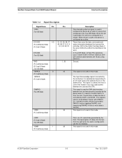
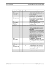
SanDisk CompactFlash Card OEM Product Manual Interface Description Table 3-4 Signal Description Signal Name Dir. D15-D00 I/O 31, 30, 29, 28, 27, These lines carry the data, commands and (PC Card Memory Mode) (PC Card I/O Mode) 49, 48, 47, 6, 5, 4, 3, 2, 23, 22, 21 status information between host and device and is asserted by the host to control the enable of the ...
SanDisk CompactFlash Card OEM Product Manual Interface Description Table 3-4 Signal Description Signal Name Dir. D15-D00 I/O 31, 30, 29, 28, 27, These lines carry the data, commands and (PC Card Memory Mode) (PC Card I/O Mode) 49, 48, 47, 6, 5, 4, 3, 2, 23, 22, 21 status information between host and device and is asserted by the host to control the enable of the ...
Product Manual
Page 24
...card during memory cycles to distinguish between Common Memory and Register (Attribute) Memory accesses: High for common memory, and low for attribute memory. No access of the signal (trailing edge). The RDY/-BSY signal is held low when the card is an output enable strobe generated by the host. Interface Description SanDisk CompactFlash Card OEM Product Manual...-up or reset function. I /O operation, this signal is set high when the card is ready to accept a new data transfer operation and held high (disabled from the card in Memory Mode and to the host. In True IDE Mode, this...
...card during memory cycles to distinguish between Common Memory and Register (Attribute) Memory accesses: High for common memory, and low for attribute memory. No access of the signal (trailing edge). The RDY/-BSY signal is held low when the card is an output enable strobe generated by the host. Interface Description SanDisk CompactFlash Card OEM Product Manual...-up or reset function. I /O operation, this signal is set high when the card is ready to accept a new data transfer operation and held high (disabled from the card in Memory Mode and to the host. In True IDE Mode, this...
Product Manual
Page 25
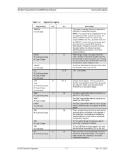
...) RESET I (PC Card Memory Mode) (PC Card I/O Mode) -RESET (True IDE Mode) VCC -- (PC Card Memory Mode) (PC Card I/O Mode) (True IDE Mode) -VS1 O -VS2 (PC Card Memory Mode) (PC Card I/O Mode) (True IDE Mode) -WAIT O (PC Card Memory Mode) -WAIT (PC Card I/O Mode) IORDY (True IDE Mode) -WE I (PC Card Memory Mode) -WE (PC Card I /O Mode, this signal resets the card. SanDisk CompactFlash Card OEM Product Manual Interface Description Table...
...) RESET I (PC Card Memory Mode) (PC Card I/O Mode) -RESET (True IDE Mode) VCC -- (PC Card Memory Mode) (PC Card I/O Mode) (True IDE Mode) -VS1 O -VS2 (PC Card Memory Mode) (PC Card I/O Mode) (True IDE Mode) -WAIT O (PC Card Memory Mode) -WAIT (PC Card I/O Mode) IORDY (True IDE Mode) -WE I (PC Card Memory Mode) -WE (PC Card I /O Mode, this signal resets the card. SanDisk CompactFlash Card OEM Product Manual Interface Description Table...

Product Manual
Page 49
...CompactFlash Memory Card features the host can utilize. Bit Name Description D7 BBK Set when a bad block is specified. D2 ABRT Set if the command has been aborted because of the Logical Block Address (LBA) for any CompactFlash Memory Card data access for the subsequent command. © 2007 SanDisk...an invalid command has been issued. SanDisk CompactFlash Card OEM Product Manual ATA Register Set and Protocol Table 4-6 Data Register Data Register Error/Feature Register Error/Feature Register CE2- D6 UNC Set when an uncorrectable error is "0" at command completion. ...
...CompactFlash Memory Card features the host can utilize. Bit Name Description D7 BBK Set when a bad block is specified. D2 ABRT Set if the command has been aborted because of the Logical Block Address (LBA) for any CompactFlash Memory Card data access for the subsequent command. © 2007 SanDisk...an invalid command has been issued. SanDisk CompactFlash Card OEM Product Manual ATA Register Set and Protocol Table 4-6 Data Register Data Register Error/Feature Register Error/Feature Register CE2- D6 UNC Set when an uncorrectable error is "0" at command completion. ...

Product Manual
Page 51
... cleared at power-up and remains cleared until card is used to control the CompactFlash Memory Card interrupt request and to issue an ATA soft reset to accept a command. D1 0 Always set , indicates a write fault has occurred. Offset Eh) This register is ready to the card. SanDisk CompactFlash Card OEM Product Manual ATA Register Set and Protocol 4.5.9 Status & Alternate Status Registers (Address-1F7...
... cleared at power-up and remains cleared until card is used to control the CompactFlash Memory Card interrupt request and to issue an ATA soft reset to accept a command. D1 0 Always set , indicates a write fault has occurred. Offset Eh) This register is ready to the card. SanDisk CompactFlash Card OEM Product Manual ATA Register Set and Protocol 4.5.9 Status & Alternate Status Registers (Address-1F7...

Product Manual
Page 64
... 82 Description Bit Setting Indication 0 0 SMART feature set not supported 1 1 Security Mode feature set supported 2 0 Removable Media feature set not supported 3 1 Power Management feature set supported 4 0 Packet Command feature set not supported 5 1 Write cache supported 6 1 Look-ahead supported 7 0 Release Interrupt not supported 8 0 Service Interrupt not supported 9 0 Device Reset command not supported 10 0 Host Protected Area feature set not supported by CF Card 15 --- ATA Command Description SanDisk CompactFlash Card OEM Product Manual Word 68...
... 82 Description Bit Setting Indication 0 0 SMART feature set not supported 1 1 Security Mode feature set supported 2 0 Removable Media feature set not supported 3 1 Power Management feature set supported 4 0 Packet Command feature set not supported 5 1 Write cache supported 6 1 Look-ahead supported 7 0 Release Interrupt not supported 8 0 Service Interrupt not supported 9 0 Device Reset command not supported 10 0 Host Protected Area feature set not supported by CF Card 15 --- ATA Command Description SanDisk CompactFlash Card OEM Product Manual Word 68...

Product Manual
Page 65
... set not supported by CF Card Word 163: CF Advanced True IDE Timing Mode Capabilities and Settings. There are four separate fields defined that the features/command sets enabled words are valid. This word describes the capabilities and current settings for CFA defined advanced timing modes using the True IDE interface. The older modes are reserved. SanDisk CompactFlash Card OEM Product Manual...
... set not supported by CF Card Word 163: CF Advanced True IDE Timing Mode Capabilities and Settings. There are four separate fields defined that the features/command sets enabled words are valid. This word describes the capabilities and current settings for CFA defined advanced timing modes using the True IDE interface. The older modes are reserved. SanDisk CompactFlash Card OEM Product Manual...

Product Manual
Page 70
Disk errors encountered during Read Multiple commands are not generated on the transfer of corrupted data, if any. This command reads from 1 to 256 sectors as it normally would, including transfer of a block, which must be ... that the number of sectors defined by a Set Multiple command is transferred without intervening interrupts is programmed by the Set Multiple Mode command, which contains the number of the data block, not on a Read Sector(s) Command. ATA Command Description SanDisk CompactFlash Card OEM Product Manual 5.1.11 Read Multiple-C4H The Read Multiple command...
Disk errors encountered during Read Multiple commands are not generated on the transfer of corrupted data, if any. This command reads from 1 to 256 sectors as it normally would, including transfer of a block, which must be ... that the number of sectors defined by a Set Multiple command is transferred without intervening interrupts is programmed by the Set Multiple Mode command, which contains the number of the data block, not on a Read Sector(s) Command. ATA Command Description SanDisk CompactFlash Card OEM Product Manual 5.1.11 Read Multiple-C4H The Read Multiple command...

Product Manual
Page 73
... error Corrected ECC error Self test or diagnostic failed ID not found Spare sectors exhausted Data transfer error/aborted command Corrupted media format Write/erase failed 5.1.17 Seek-7XH This command is effectively a NOP command to the card although...(2) X Feature (1) X © 2007 SanDisk Corporation 5-19 Rev. 12.0, 02/07 The extended error code is out of range. SanDisk CompactFlash Card OEM Product Manual ATA Command Description Table 5-24 defines the valid extended error codes for the CompactFlash Memory Card Series product. This command must be the next command issued...
... error Corrected ECC error Self test or diagnostic failed ID not found Spare sectors exhausted Data transfer error/aborted command Corrupted media format Write/erase failed 5.1.17 Seek-7XH This command is effectively a NOP command to the card although...(2) X Feature (1) X © 2007 SanDisk Corporation 5-19 Rev. 12.0, 02/07 The extended error code is out of range. SanDisk CompactFlash Card OEM Product Manual ATA Command Description Table 5-24 defines the valid extended error codes for the CompactFlash Memory Card Series product. This command must be the next command issued...

Product Manual
Page 74
...issued, all features that are supported. Disable 8-bit data transfer Accepted for backward compatibility with the SDP Series but has no impact on the CF Memory Card Accepted for backward compatibility with the SDP Series but ...07, Rev. 12.0 5-20 © 2007 SanDisk Corporation The 9AH feature is unique to enable and clear 8-bit data transfer mode. ATA Command Description SanDisk CompactFlash Card OEM Product Manual 5.1.18 Set Features-EFH This command is used to CompactFlash Memory cards and are not part of the ATA Specification. Table 5-26 Set Features Bit 7 6 5 4 3 2 1...
...issued, all features that are supported. Disable 8-bit data transfer Accepted for backward compatibility with the SDP Series but has no impact on the CF Memory Card Accepted for backward compatibility with the SDP Series but ...07, Rev. 12.0 5-20 © 2007 SanDisk Corporation The 9AH feature is unique to enable and clear 8-bit data transfer mode. ATA Command Description SanDisk CompactFlash Card OEM Product Manual 5.1.18 Set Features-EFH This command is used to CompactFlash Memory cards and are not part of the ATA Specification. Table 5-26 Set Features Bit 7 6 5 4 3 2 1...


