
Canadian English Manual
Page 2
WEIDER is missing or illegible, see the front cover of this manual and request a free replacement decal. TABLE OF CONTENTS WARNING DECAL PLACEMENT 2 IMPORTANT PRECAUTIONS 3 BEFORE YOU BEGIN 4 PART IDENTIFICATION CHART 5 ASSEMBLY 6 ADJUSTMENT 18 WEIGHT RESISTANCE CHART 20 CABLE DIAGRAM 21 MAINTENANCE 22 EXERCISE GUIDELINES 23 PART LIST 25 EXPLODED DRAWING 26 ORDERING REPLACEMENT...
WEIDER is missing or illegible, see the front cover of this manual and request a free replacement decal. TABLE OF CONTENTS WARNING DECAL PLACEMENT 2 IMPORTANT PRECAUTIONS 3 BEFORE YOU BEGIN 4 PART IDENTIFICATION CHART 5 ASSEMBLY 6 ADJUSTMENT 18 WEIGHT RESISTANCE CHART 20 CABLE DIAGRAM 21 MAINTENANCE 22 EXERCISE GUIDELINES 23 PART LIST 25 EXPLODED DRAWING 26 ORDERING REPLACEMENT...

Canadian English Manual
Page 4
... number and serial number before you want. To help you for selecting the versatile WEIDER® 2980 X weight system. High Pulley Station Arm Pin Right Side Backrest Curl Pad Seat Leg Lever Pin Leg Lever Low Pulley Station Foot Plate ASSEMBLED DIMENSIONS: Height: 6 ft. 4 in. (193 cm) Width: 3 ft. 1 in. (94 cm) Depth: 5 ft...
... number and serial number before you want. To help you for selecting the versatile WEIDER® 2980 X weight system. High Pulley Station Arm Pin Right Side Backrest Curl Pad Seat Leg Lever Pin Leg Lever Low Pulley Station Foot Plate ASSEMBLED DIMENSIONS: Height: 6 ft. 4 in. (193 cm) Width: 3 ft. 1 in. (94 cm) Depth: 5 ft...
Canadian English Manual
Page 6
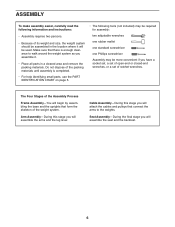
...a set of open-end or closed-end wrenches, or a set of the packing materials until assembly is enough clearance to the weights. Make sure that form the skeleton of its weight and size, the weight system should be assembled in the location where it . • Place all parts in a cleared area and remove the... this stage you will attach the cables and pulleys that connect the arms to walk around the weight system as you will begin by assembling the base and the uprights that there is completed. • For help identifying small parts, use the PART IDENTIFICATION CHART on page 5. •...
...a set of open-end or closed-end wrenches, or a set of the packing materials until assembly is enough clearance to the weights. Make sure that form the skeleton of its weight and size, the weight system should be assembled in the location where it . • Place all parts in a cleared area and remove the... this stage you will attach the cables and pulleys that connect the arms to walk around the weight system as you will begin by assembling the base and the uprights that there is completed. • For help identifying small parts, use the PART IDENTIFICATION CHART on page 5. •...

Canadian English Manual
Page 7
... (21) as shown, so the indicated holes are closer to the lower ends. 2 Attach the Weight Guides and the Stabilizer (2) to hold them in place. 2. Frame Assembly 1 1. To make assembly easier, read the information on page 6 before you begin. Insert four M8 x 63mm Carriage Bolts (64) up through the Base (1). Attach the Upright...
... (21) as shown, so the indicated holes are closer to the lower ends. 2 Attach the Weight Guides and the Stabilizer (2) to hold them in place. 2. Frame Assembly 1 1. To make assembly easier, read the information on page 6 before you begin. Insert four M8 x 63mm Carriage Bolts (64) up through the Base (1). Attach the Upright...

Canadian English Manual
Page 9
... an M10 x 155mm Bolt (74), two M10 Washers (57), two 19mm Spacers (76), and an M10 Nylon Locknut (56). Attach the Top Frame (4) between the Weight Guides (21) with two M4 x 20mm Self-tapping Screws (69). Orient the Leg Lever (8) with the Bolt and an M10 Nylon Locknut (56). Attach the... 3 Grease 69 40 Tighten the M8 Nylon Locknuts (58). 59 4 68 59 76 76 56 57 57 74 Welded Support 58 58 3 21 21 Arm Assembly 7. the Pivot Frame must pivot easily. 7 56 8 Welded Support 7 Grease 79 8. Attach the Leg Lever to the Upright (3) with the Bolt and an M10 Nylon...
... an M10 x 155mm Bolt (74), two M10 Washers (57), two 19mm Spacers (76), and an M10 Nylon Locknut (56). Attach the Top Frame (4) between the Weight Guides (21) with two M4 x 20mm Self-tapping Screws (69). Orient the Leg Lever (8) with the Bolt and an M10 Nylon Locknut (56). Attach the... 3 Grease 69 40 Tighten the M8 Nylon Locknuts (58). 59 4 68 59 76 76 56 57 57 74 Welded Support 58 58 3 21 21 Arm Assembly 7. the Pivot Frame must pivot easily. 7 56 8 Welded Support 7 Grease 79 8. Attach the Leg Lever to the Upright (3) with the Bolt and an M10 Nylon...

Canadian English Manual
Page 21
If the cables are assembled correctly. Use the diagram to make sure that the cable traps do not touch or bind the cables. High Cable (55) Length: 9 ft. 6 in. (290 ...: 10 ft. 8 in each drawing show the proper route of the cables. Make sure that the cables, cable traps, pulleys, and guards are not assembled correctly, the weight system will not function properly and damage may occur. CABLE DIAGRAM The diagram below shows the proper routing of that cable. The numbers in...
If the cables are assembled correctly. Use the diagram to make sure that the cable traps do not touch or bind the cables. High Cable (55) Length: 9 ft. 6 in. (290 ...: 10 ft. 8 in each drawing show the proper route of the cables. Make sure that the cables, cable traps, pulleys, and guards are not assembled correctly, the weight system will not function properly and damage may occur. CABLE DIAGRAM The diagram below shows the proper routing of that cable. The numbers in...


