
Makita DC18RC Instruction Manual
Page 3
..., ask Makita authorized service center to replace it has received a sharp blow, been dropped, or otherwise dam- SAVE THESE INSTRUCTIONS - This manual contains important safety and operating instructions for a long period of the battery cartridge, such as to damage or stress. 11. IMPORTANT SAFETY INSTRUCTIONS CAUTION: 1. Other types of charger. aged in green color repeatedly. 2. Young children should be opened with inserting and closed...
..., ask Makita authorized service center to replace it has received a sharp blow, been dropped, or otherwise dam- SAVE THESE INSTRUCTIONS - This manual contains important safety and operating instructions for a long period of the battery cartridge, such as to damage or stress. 11. IMPORTANT SAFETY INSTRUCTIONS CAUTION: 1. Other types of charger. aged in green color repeatedly. 2. Young children should be opened with inserting and closed...
Makita DC18RC Instruction Manual
Page 4
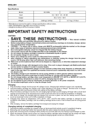
... be sent to repair or maintenance, if the yellow warning light will flash for cooling. • The products should be sometime clogged with its own performance. Recharge of battery cartridge and maintenance charge. 4 BH9033A - 12 V 10 - - BH1420 - - Battery cartridge from just-operated tool or battery cartridge that case, yellow light lights up. 1. When the battery cartridge is not possible. The battery employed in spite...
... be sent to repair or maintenance, if the yellow warning light will flash for cooling. • The products should be sometime clogged with its own performance. Recharge of battery cartridge and maintenance charge. 4 BH9033A - 12 V 10 - - BH1420 - - Battery cartridge from just-operated tool or battery cartridge that case, yellow light lights up. 1. When the battery cartridge is not possible. The battery employed in spite...

XPK01Z Instruction Manual
Page 2
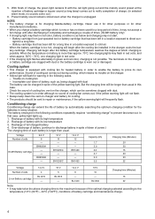
... research and development, the specifications herein are subject to change without notice. • Specifications and battery cartridge may differ from heat, oil, sharp edges or moving parts. Never use . Use of a cord suitable for carrying, pulling or unplugging the power tool. Always wear eye protection. A wrench or a key left attached to country. • Weight, with your mains-operated (corded) power tool or battery-operated (cordless) power tool. Electrical safety 4. Do not use a power tool while you are tired...
... research and development, the specifications herein are subject to change without notice. • Specifications and battery cartridge may differ from heat, oil, sharp edges or moving parts. Never use . Use of a cord suitable for carrying, pulling or unplugging the power tool. Always wear eye protection. A wrench or a key left attached to country. • Weight, with your mains-operated (corded) power tool or battery-operated (cordless) power tool. Electrical safety 4. Do not use a power tool while you are tired...
XPK01Z Instruction Manual
Page 3
... situation. Service 28. Keep handles dry, clean and free from rotating parts. 9. GEB064-2 CORDLESS PLANER SAFETY WARNINGS 1. An exposed rotating cutter may lead to possible loss of untrained users. 21. Holding the work by a qualified repair person using the tool on . 11. Handle the blades very carefully. 6. Before using only identical replacement parts. Watch for operations different from the workpiece before use the power tool if the switch does not turn it...
... situation. Service 28. Keep handles dry, clean and free from rotating parts. 9. GEB064-2 CORDLESS PLANER SAFETY WARNINGS 1. An exposed rotating cutter may lead to possible loss of untrained users. 21. Holding the work by a qualified repair person using the tool on . 11. Handle the blades very carefully. 6. Before using only identical replacement parts. Watch for operations different from the workpiece before use the power tool if the switch does not turn it...

XPK01Z Instruction Manual
Page 4
.... 5. Operate the tool only when hand-held. 15. It may result in a container with room temperature at 10 ゚ C - 40 ゚ C (50 ゚ F - 104 ゚ F). Tips for tool. ・ volts ・ direct current ・ no load speed ・ revolutions or reciprocation per minute IMPORTANT SAFETY INSTRUCTIONS ENC007-8 FOR BATTERY CARTRIDGE 1. USD301-1 Symbols The followings show the symbols used for maintaining maximum battery life...
.... 5. Operate the tool only when hand-held. 15. It may result in a container with room temperature at 10 ゚ C - 40 ゚ C (50 ゚ F - 104 ゚ F). Tips for tool. ・ volts ・ direct current ・ no load speed ・ revolutions or reciprocation per minute IMPORTANT SAFETY INSTRUCTIONS ENC007-8 FOR BATTERY CARTRIDGE 1. USD301-1 Symbols The followings show the symbols used for maintaining maximum battery life...
XPK01Z Instruction Manual
Page 5
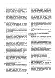
... cannot be adjusted by simply turning the knob on the upper side of cut . Star marking 012128 Lithium-ion batteries with a star marking are placed under one of cut 1. This system automatically cuts off power to the tool to restart. To install the battery cartridge, align the tongue on the tool and stop during operation if the tool and/or battery are equipped with star marking) 1 1. Insert it into...
... cannot be adjusted by simply turning the knob on the upper side of cut . Star marking 012128 Lithium-ion batteries with a star marking are placed under one of cut 1. This system automatically cuts off power to the tool to restart. To install the battery cartridge, align the tongue on the tool and stop during operation if the tool and/or battery are equipped with star marking) 1 1. Insert it into...
XPK01Z Instruction Manual
Page 6
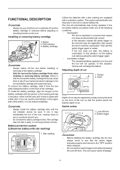
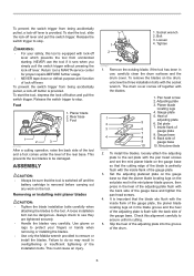
... tool. Mini planer blade 002565 2. Adjusting plate 3. Gauge base 4 8 9. Inside flank of the gauge base. ASSEMBLY CAUTION: • Always be sure that the blade sits flush with the blades. 1. A loose installation bolt can be damaged. Bolt 3. Pan head screw 2. WARNING: • For your fingers or hands when removing or installing the blades. • Use only the Makita wrench provided to stop . Planer blade locating lugs 4. This could cause an injury. 4 3 1 2 1. To start the tool, slide the lock...
... tool. Mini planer blade 002565 2. Adjusting plate 3. Gauge base 4 8 9. Inside flank of the gauge base. ASSEMBLY CAUTION: • Always be sure that the blade sits flush with the blades. 1. A loose installation bolt can be damaged. Bolt 3. Pan head screw 2. WARNING: • For your fingers or hands when removing or installing the blades. • Use only the Makita wrench provided to stop . Planer blade locating lugs 4. This could cause an injury. 4 3 1 2 1. To start the tool, slide the lock...
XPK01Z Instruction Manual
Page 7
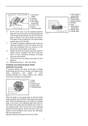
... set plate. 7. Inside edge of gauge base 8. Planer blade 4. Installing conventional planer blade (optional accessory) To install the blades, first clean out all the installation bolts evenly and alternately with the socket wrench provided) and hand rotate the drum to slide the mini planer blade into the drum groove, then fit the drum cover on the adjusting plate. Adjusting plate 1 5. Screws 6. 1 6 1. Drum 2 7. Check the three hex flange head bolts for other blade. 2 3 4 5 6 7 002556 7 1. Use blades...
... set plate. 7. Inside edge of gauge base 8. Planer blade 4. Installing conventional planer blade (optional accessory) To install the blades, first clean out all the installation bolts evenly and alternately with the socket wrench provided) and hand rotate the drum to slide the mini planer blade into the drum groove, then fit the drum cover on the adjusting plate. Adjusting plate 1 5. Screws 6. 1 6 1. Drum 2 7. Check the three hex flange head bolts for other blade. 2 3 4 5 6 7 002556 7 1. Use blades...

XPK01Z Instruction Manual
Page 8
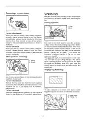
... contents, tapping it lightly so as to remove particles adhering to rear base line. Attach the dust bag onto the nozzle . Empty the dust bag of the rear base. The blade must be performed. 8 For tool with nozzle Attach the dust bag onto the nozzle. Cause: One or both blade edges (B) fails to protrude enough in surface Gouging at start (A) Gouging at...
... contents, tapping it lightly so as to remove particles adhering to rear base line. Attach the dust bag onto the nozzle . Empty the dust bag of the rear base. The blade must be performed. 8 For tool with nozzle Attach the dust bag onto the nozzle. Cause: One or both blade edges (B) fails to protrude enough in surface Gouging at start (A) Gouging at...
XPK01Z Instruction Manual
Page 9
... operation, connect a Makita vacuum cleaner to your tool. To remove it, just pull it . For rough cutting, the depth of cut as shown in the figure, use the edge fence (guide rule) which is obtained as shown in the figures. Then connect a hose of cut determine the kind of the tool by chips. The power planer keeps cutting at the end of chip discharge direction to your tool. Blade edge...
... operation, connect a Makita vacuum cleaner to your tool. To remove it, just pull it . For rough cutting, the depth of cut as shown in the figure, use the edge fence (guide rule) which is obtained as shown in the figures. Then connect a hose of cut determine the kind of the tool by chips. The power planer keeps cutting at the end of chip discharge direction to your tool. Blade edge...

XPK01Z Instruction Manual
Page 10
... by attaching an extra piece of the tool. Maximum shiplapping (rabbeting) depth is removed before attempting to remove nicks and produce a fine edge. 10 MAINTENANCE CAUTION: • Always be sure that the tool is switched off and the battery cartridge is 9 mm (11/32"). 010183 You may wish to add to the length of the fence by tightening the screw. 003634 011761 When...
... by attaching an extra piece of the tool. Maximum shiplapping (rabbeting) depth is removed before attempting to remove nicks and produce a fine edge. 10 MAINTENANCE CAUTION: • Always be sure that the tool is switched off and the battery cartridge is 9 mm (11/32"). 010183 You may wish to add to the length of the fence by tightening the screw. 003634 011761 When...
XPK01Z Instruction Manual
Page 11
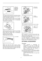
... 2. Replacing carbon brushes 1. Keep the carbon brushes clean and free to remove the brush holder caps. Both carbon brushes should be replaced at the same angle. 011749 1 2 1. Then tighten the wing nuts. Screwdriver 1 2 1. Brush holder cap 2. OPTIONAL ACCESSORIES CAUTION: • These accessories or attachments are recommended for simultaneous sharpening at the same angle. Hold the holder so that the blades both blades contact the dressing stone for use with your local Makita Service Center. • High-speed steel...
... 2. Replacing carbon brushes 1. Keep the carbon brushes clean and free to remove the brush holder caps. Both carbon brushes should be replaced at the same angle. 011749 1 2 1. Then tighten the wing nuts. Screwdriver 1 2 1. Brush holder cap 2. OPTIONAL ACCESSORIES CAUTION: • These accessories or attachments are recommended for simultaneous sharpening at the same angle. Hold the holder so that the blades both blades contact the dressing stone for use with your local Makita Service Center. • High-speed steel...
XPK01Z Instruction Manual
Page 12
... Warranty gives you specific legal rights, and you . IN NO EVENT SHALL MAKITA BE LIABLE FOR ANY INDIRECT, INCIDENTAL OR CONSEQUENTIAL DAMAGES FROM THE SALE OR USE OF THE PRODUCT. • Blade gauge • Set plates set • Edge fence (Guide rule) • Extension guide set • Dressing stone • Nozzle • Dust bag assembly • Elbow • Socket wrench • Plastic carrying case • Makita genuine battery and charger NOTE...
... Warranty gives you specific legal rights, and you . IN NO EVENT SHALL MAKITA BE LIABLE FOR ANY INDIRECT, INCIDENTAL OR CONSEQUENTIAL DAMAGES FROM THE SALE OR USE OF THE PRODUCT. • Blade gauge • Set plates set • Edge fence (Guide rule) • Extension guide set • Dressing stone • Nozzle • Dust bag assembly • Elbow • Socket wrench • Plastic carrying case • Makita genuine battery and charger NOTE...

XPK01Z Parts Breakdown
Page 2
... CARBON BRUSH CB-441 (195022-4) 007 643829-7 HOLDER CAP 008 419664-3 LOCK OFF LEVER 009 231469-9 COMPRESSION SPRING 4 010 419665-1 SWITCH LEVER 011 142578-8 MAIN FRAME COMPLETE 011 C10 263005-3 RUBBER PIN 6 011 C20 803H94-0 CAUTION LABEL 012 451328-3 KNOB COVER 013 961004-6 RETAINING RING S-8 014 264028-4 HEX. NUT M10 015 452793-9 KNOB 016 232185-6 LEAF SPRING 017 346110-2 CAM PLATE 018 911128-8 PAN HEAD SCREW...
... CARBON BRUSH CB-441 (195022-4) 007 643829-7 HOLDER CAP 008 419664-3 LOCK OFF LEVER 009 231469-9 COMPRESSION SPRING 4 010 419665-1 SWITCH LEVER 011 142578-8 MAIN FRAME COMPLETE 011 C10 263005-3 RUBBER PIN 6 011 C20 803H94-0 CAUTION LABEL 012 451328-3 KNOB COVER 013 961004-6 RETAINING RING S-8 014 264028-4 HEX. NUT M10 015 452793-9 KNOB 016 232185-6 LEAF SPRING 017 346110-2 CAM PLATE 018 911128-8 PAN HEAD SCREW...

XPK01Z Parts Breakdown
Page 3
FLANGE HEAD BOLT M6X17 053 815K72-6 XPK01 NAME PLATE 055 644808-8 TERMINAL A03 123062-2 BLADE GAUGE ASS'Y A03 C10 911228-4 PAN HEAD SCREW M5X18 A03 C20 411086-3 GAUGE PLATE A04 782209-3 SOCKET WRENCH 9 1 PC. 1 PC. 1 SET 2 PC. 2 PC. 4 PC. 1 SET 6 PC. 1 1 PC. 1 PC. 2 PC. 1 PC. 1 PC. 045 161061-6 DRUM 046 211032-4 BALL BEARING 608ZZ 047 D-46246 T.C.T. MINI PLANER BLADE 048 343433-9 SET PLATE F/MINI BLADE 049 345644-2 ADJUST PLATE 050 265132-2 + PAN HEAD SCREW M4X5 051 187679-5 DRUM PLATE SET 052 251609-3 HEX.
FLANGE HEAD BOLT M6X17 053 815K72-6 XPK01 NAME PLATE 055 644808-8 TERMINAL A03 123062-2 BLADE GAUGE ASS'Y A03 C10 911228-4 PAN HEAD SCREW M5X18 A03 C20 411086-3 GAUGE PLATE A04 782209-3 SOCKET WRENCH 9 1 PC. 1 PC. 1 SET 2 PC. 2 PC. 4 PC. 1 SET 6 PC. 1 1 PC. 1 PC. 2 PC. 1 PC. 1 PC. 045 161061-6 DRUM 046 211032-4 BALL BEARING 608ZZ 047 D-46246 T.C.T. MINI PLANER BLADE 048 343433-9 SET PLATE F/MINI BLADE 049 345644-2 ADJUST PLATE 050 265132-2 + PAN HEAD SCREW M4X5 051 187679-5 DRUM PLATE SET 052 251609-3 HEX.


