

User Guide
Page 7
... Cable ...18 2.5.1 Attach Wire Mounts ...18 2.5.2 Insert Fiber-optic Cable 19 2.5.3 Connect The Fiber-optic Cable To The Transceiver 19 2.6 Close the MC1000-SFP-FP 20 2.7 Replacing An SFP Transceiver 21 2.7.1 Procedure To Remove An SFP Transceiver 21 Chapter 3 Deploying the MC1000-SFP-FP 23 3.1 Overview ...23 3.2 LAN Connection ...23 3.3 Power Connection ...23 3.4 Front Panel LEDs ...24 3.5 Wall-mounting Instructions 25...
... Cable ...18 2.5.1 Attach Wire Mounts ...18 2.5.2 Insert Fiber-optic Cable 19 2.5.3 Connect The Fiber-optic Cable To The Transceiver 19 2.6 Close the MC1000-SFP-FP 20 2.7 Replacing An SFP Transceiver 21 2.7.1 Procedure To Remove An SFP Transceiver 21 Chapter 3 Deploying the MC1000-SFP-FP 23 3.1 Overview ...23 3.2 LAN Connection ...23 3.3 Power Connection ...23 3.4 Front Panel LEDs ...24 3.5 Wall-mounting Instructions 25...

User Guide
Page 9
...MC1000-SFP-FP Example Application 1 13 Figure 2 MC1000-SFP-FP Example Application 2 13 Figure 3 No Link-Fault Signaling ...14 Figure 4 With Link-Fault Signaling ...14 Figure 5 Remove The Housing Screws 15 Figure 6 Open The Cover ...16 Figure 7 Transceiver Slot ...17 Figure 8 Install An SFP Transceiver ...17 Figure 9 Lock Transceiver... Screws 20 Figure 15 Remove Fiber-optic Cable ...21 Figure 16 Unlock The Transceiver ...21 Figure 17 Remove Transceiver ...21 Figure 18 LAN Connection ...23 Figure 19 Power Connection ...24 Figure 20 MC1000-SFP-FP LEDs ...25 Figure 21 Wall-mounting Example ...26...
...MC1000-SFP-FP Example Application 1 13 Figure 2 MC1000-SFP-FP Example Application 2 13 Figure 3 No Link-Fault Signaling ...14 Figure 4 With Link-Fault Signaling ...14 Figure 5 Remove The Housing Screws 15 Figure 6 Open The Cover ...16 Figure 7 Transceiver Slot ...17 Figure 8 Install An SFP Transceiver ...17 Figure 9 Lock Transceiver... Screws 20 Figure 15 Remove Fiber-optic Cable ...21 Figure 16 Unlock The Transceiver ...21 Figure 17 Remove Transceiver ...21 Figure 18 LAN Connection ...23 Figure 19 Power Connection ...24 Figure 20 MC1000-SFP-FP LEDs ...25 Figure 21 Wall-mounting Example ...26...
User Guide
Page 15
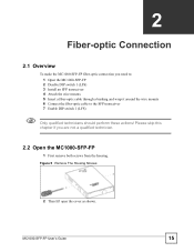
... 2 Fiber-optic Connection 2.1 Overview To make the MC1000-SFP-FP fiber-optic connection you are not a qualified technician. 2.2 Open the MC1000-SFP-FP 1 First remove both screws from the housing. MC1000-SFP-FP User's Guide 15 Please skip this chapter if you need to: 1 Open the MC1000-SFP-FP 2 Disable DIP switch 1 (LFS) 3 Install an SFP transceiver 4 Attach the wire mounts 5 Insert a fiber-optic...
... 2 Fiber-optic Connection 2.1 Overview To make the MC1000-SFP-FP fiber-optic connection you are not a qualified technician. 2.2 Open the MC1000-SFP-FP 1 First remove both screws from the housing. MC1000-SFP-FP User's Guide 15 Please skip this chapter if you need to: 1 Open the MC1000-SFP-FP 2 Disable DIP switch 1 (LFS) 3 Install an SFP transceiver 4 Attach the wire mounts 5 Insert a fiber-optic...

User Guide
Page 16
...the following warnings when working correctly. 2.4 Install A Transceiver The MC1000-SFP-FP supports MSA (Multi-Source Agreement) compliant SFP transceivers. Chapter 2 Fiber-optic Connection Figure 6 Open The Cover 2.3 DIP Switch 1 The MC1000-SFP-FP supports Link-Fault Signaling (LFS). Ignore the other...the printed circuit board inside the MC1000-SFP-FP. Inside the MC1000-SFP-FP, there is working with an LC-type connector. See Section 1.1.1 on page 13 for an SFP transceiver with transceivers! 16 MC1000-SFP-FP User's Guide SFP transceivers provide duplex single-mode or multi...
...the following warnings when working correctly. 2.4 Install A Transceiver The MC1000-SFP-FP supports MSA (Multi-Source Agreement) compliant SFP transceivers. Chapter 2 Fiber-optic Connection Figure 6 Open The Cover 2.3 DIP Switch 1 The MC1000-SFP-FP supports Link-Fault Signaling (LFS). Ignore the other...the printed circuit board inside the MC1000-SFP-FP. Inside the MC1000-SFP-FP, there is working with an LC-type connector. See Section 1.1.1 on page 13 for an SFP transceiver with transceivers! 16 MC1000-SFP-FP User's Guide SFP transceivers provide duplex single-mode or multi...
User Guide
Page 17
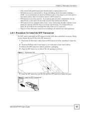
... into the optical bores, as the optics do not work correctly when obstructed with dust. • SFP transceivers are static sensitive. Figure 8 Install An SFP Transceiver . MC1000-SFP-FP User's Guide 17 Figure 7 Transceiver Slot 5 Insert the SFP transceiver into the slot until the SFP transceiver snaps into place. Chapter 2 Fiber-optic Connection • Only trained and qualified personnel should install or...
... into the optical bores, as the optics do not work correctly when obstructed with dust. • SFP transceivers are static sensitive. Figure 8 Install An SFP Transceiver . MC1000-SFP-FP User's Guide 17 Figure 7 Transceiver Slot 5 Insert the SFP transceiver into the slot until the SFP transceiver snaps into place. Chapter 2 Fiber-optic Connection • Only trained and qualified personnel should install or...

User Guide
Page 18
... of fiber optic cable you may have within the MC1000-SFP-FP in order to prevent it from the wire mounts and attach them to the sides of the MC1000-SFP-FP as shown. 18 MC1000-SFP-FP User's Guide Chapter 2 Fiber-optic Connection " SFP transceiver installation orientation varies depending on your transceiver has a locking mechanism). Remove the adhesive cover from being...
... of fiber optic cable you may have within the MC1000-SFP-FP in order to prevent it from the wire mounts and attach them to the sides of the MC1000-SFP-FP as shown. 18 MC1000-SFP-FP User's Guide Chapter 2 Fiber-optic Connection " SFP transceiver installation orientation varies depending on your transceiver has a locking mechanism). Remove the adhesive cover from being...
User Guide
Page 19
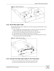
... holes (labelled A in the following figure) through which you may insert fiber-optic cable. 1 Insert a bushing into the SFP transceiver. MC1000-SFP-FP User's Guide 19 The bushing sheathes the cable, holds it in place and covers the hole. 2 Create a hole in the bushing ... the fiber-optic cable. Figure 11 Wrap Fiber-optic Cable A A A A 2.5.3 Connect The Fiber-optic Cable To The Transceiver 1 Remove the dust plugs from the SFP transceiver and the cables. 2 Insert the end of the MC1000-SFP-FP using the wire mounts as shown in the following figure. Figure 10 Attach Wire Mounts.
... holes (labelled A in the following figure) through which you may insert fiber-optic cable. 1 Insert a bushing into the SFP transceiver. MC1000-SFP-FP User's Guide 19 The bushing sheathes the cable, holds it in place and covers the hole. 2 Create a hole in the bushing ... the fiber-optic cable. Figure 11 Wrap Fiber-optic Cable A A A A 2.5.3 Connect The Fiber-optic Cable To The Transceiver 1 Remove the dust plugs from the SFP transceiver and the cables. 2 Insert the end of the MC1000-SFP-FP using the wire mounts as shown in the following figure. Figure 10 Attach Wire Mounts.

User Guide
Page 20
... on page 15. 1 Close the cover as shown. Figure 14 Replace Housing Cover Screws 20 MC1000-SFP-FP User's Guide Chapter 2 Fiber-optic Connection Figure 12 Insert Cable 2.6 Close the MC1000-SFP-FP After you have disabled DIP switch 1 (LFS), installed the SFP transceiver, attached the wire mounts, threaded fiber-optic cable though a bushing, wrapped excessive fiber-optic...
... on page 15. 1 Close the cover as shown. Figure 14 Replace Housing Cover Screws 20 MC1000-SFP-FP User's Guide Chapter 2 Fiber-optic Connection Figure 12 Insert Cable 2.6 Close the MC1000-SFP-FP After you have disabled DIP switch 1 (LFS), installed the SFP transceiver, attached the wire mounts, threaded fiber-optic cable though a bushing, wrapped excessive fiber-optic...

User Guide
Page 21
...insert a new one as documented previously. 2.7.1 Procedure To Remove An SFP Transceiver 1 Attach an ESD preventive wrist strap to your thumb and index finger, grasp both sides of the transceiver and carefully slide it out of a slot. MC1000-SFP-FP User's Guide 21 Figure 15 Remove Fiber-optic Cable 3 Insert the... dust plug into the port on the SFP transceiver. 4 Pull the latch out and down to a bare metal...
...insert a new one as documented previously. 2.7.1 Procedure To Remove An SFP Transceiver 1 Attach an ESD preventive wrist strap to your thumb and index finger, grasp both sides of the transceiver and carefully slide it out of a slot. MC1000-SFP-FP User's Guide 21 Figure 15 Remove Fiber-optic Cable 3 Insert the... dust plug into the port on the SFP transceiver. 4 Pull the latch out and down to a bare metal...

User Guide
Page 24
To turn the MC1000-SFP-FP on the top. Look at them to the SFP transceiver. Chapter 3 Deploying the MC1000-SFP-FP " Be careful not to damage the fiber optic cables if you have already connected them to quickly check the status of the MC1000-SFP-FP. 24 MC1000-SFP-FP User's Guide Figure 19 Power Connection 3.4 Front Panel LEDs The MC1000-SFP-FP LEDs are on , connect the external power supply to a power outlet.
To turn the MC1000-SFP-FP on the top. Look at them to the SFP transceiver. Chapter 3 Deploying the MC1000-SFP-FP " Be careful not to damage the fiber optic cables if you have already connected them to quickly check the status of the MC1000-SFP-FP. 24 MC1000-SFP-FP User's Guide Figure 19 Power Connection 3.4 Front Panel LEDs The MC1000-SFP-FP LEDs are on , connect the external power supply to a power outlet.

User Guide
Page 25
... an Ethernet device. The MC1000-SFP-FP is sending or receiving packets on . The MC1000-SFP-FP is sending or receiving packets on this port. Fiber-optic and Ethernet links to a fiber-optic link. The MC1000-SFP-FP is turned on this port. The SFP transceiver is no traffic on this port. There is connected to the MC1000-SFP-FP are operating normally. The...
... an Ethernet device. The MC1000-SFP-FP is sending or receiving packets on . The MC1000-SFP-FP is sending or receiving packets on this port. Fiber-optic and Ethernet links to a fiber-optic link. The MC1000-SFP-FP is turned on this port. The SFP transceiver is no traffic on this port. There is connected to the MC1000-SFP-FP are operating normally. The...

User Guide
Page 27
...100/1000Mbps DIP Switches DIP 1 - depends on the SFP transceiver you install) Management Alarm LED illuminates to indicate link failure Status LEDs for easy monitoring of Class B & CE approved Dimensions 194 x 130 x 26 mm (L x W x H) MC1000-SFP-FP User's Guide 27 up to 500m (1,650ft) for ...multi-mode fiber module 80km (317,625ft) for single-mode fiber module (depends on the SFP transceiver you install) Cables Single-mode fiber: 9/125um Multi-mode fiber: 50/...
...100/1000Mbps DIP Switches DIP 1 - depends on the SFP transceiver you install) Management Alarm LED illuminates to indicate link failure Status LEDs for easy monitoring of Class B & CE approved Dimensions 194 x 130 x 26 mm (L x W x H) MC1000-SFP-FP User's Guide 27 up to 500m (1,650ft) for ...multi-mode fiber module 80km (317,625ft) for single-mode fiber module (depends on the SFP transceiver you install) Cables Single-mode fiber: 9/125um Multi-mode fiber: 50/...

User Guide
Page 28
Supported at the time of writing. 28 MC1000-SFP-FP User's Guide Appendix A Product Specifications Table 2 Product Specifications SPECIFICATION DESCRIPTION Weight 292g SFP Transceivers Supported transceiversA Use 3.3V power input and LC-type connectors. • SFP-SX • SFP-LX-10 • SFP-LHX-40 • SFP-ZX-80 • SFP-BX1310-10 • SFP-BX1490-10 A.
Supported at the time of writing. 28 MC1000-SFP-FP User's Guide Appendix A Product Specifications Table 2 Product Specifications SPECIFICATION DESCRIPTION Weight 292g SFP Transceivers Supported transceiversA Use 3.3V power input and LC-type connectors. • SFP-SX • SFP-LX-10 • SFP-LHX-40 • SFP-ZX-80 • SFP-BX1310-10 • SFP-BX1490-10 A.