

Owners Manual
Page 80
... stand 29 Rear shock absorber adjusters 30 Changing motorcycle track alignment 32 Directions for use 34 Running-in recommendations 34 Pre-ride checks 35 Starting the engine 36 Moving off 38 Braking 39 Stopping the motorcycle 40 Refuelling 40 Parking 41 Tool kit and accessories 42 Main maintenance operations Removing the fairings (S2R) 43 Lifting the fuel tank 44 Changing the air filter 45 43 General 5 Warranty 5 Symbols 5 Useful...
... stand 29 Rear shock absorber adjusters 30 Changing motorcycle track alignment 32 Directions for use 34 Running-in recommendations 34 Pre-ride checks 35 Starting the engine 36 Moving off 38 Braking 39 Stopping the motorcycle 40 Refuelling 40 Parking 41 Tool kit and accessories 42 Main maintenance operations Removing the fairings (S2R) 43 Lifting the fuel tank 44 Changing the air filter 45 43 General 5 Warranty 5 Symbols 5 Useful...

Owners Manual
Page 81
E Checking brake and clutch fluid level 46 Checking brake pads for wear 47 Lubricating cables and joints 48 Throttle cable adjustment 49 Charging the battery 50 Chain tensioning 51 Chain lubrication 52 Replacing bulbs 53 Beam setting 57 Tyres 58 Checking engine oil level 60 Cleaning and replacing the spark plugs 61 Cleaning the motorcycle 62 Storing the bike away 63 Important notes 63 Important only for Australia...
E Checking brake and clutch fluid level 46 Checking brake pads for wear 47 Lubricating cables and joints 48 Throttle cable adjustment 49 Charging the battery 50 Chain tensioning 51 Chain lubrication 52 Replacing bulbs 53 Beam setting 57 Tyres 58 Checking engine oil level 60 Cleaning and replacing the spark plugs 61 Cleaning the motorcycle 62 Storing the bike away 63 Important notes 63 Important only for Australia...
Owners Manual
Page 83
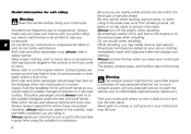
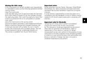
... time using the suitable turn off ; Warning The exhaust system might be ready for sudden changes of vehicles ahead. Park your motorcycle to inexperienced riders or who do not park the vehicle next to the visibility, road and traffic conditions you when riding; Accidents are posted. The pillion passenger should keep their feet on the footpegs when the motorcycle is switched off the engine...
... time using the suitable turn off ; Warning The exhaust system might be ready for sudden changes of vehicles ahead. Park your motorcycle to inexperienced riders or who do not park the vehicle next to the visibility, road and traffic conditions you when riding; Accidents are posted. The pillion passenger should keep their feet on the footpegs when the motorcycle is switched off the engine...

Owners Manual
Page 90
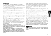
... keys. Accommodated in the switch when the ignition is turned on and changes every time. start up the engine - Warning Keep the keys in a safe place. The immobilizer system For improved antitheft protection, the motorcycle is equipped with other black keys, if needed . This signal is an electronic device that reports their identification number. open the lock of each ignition key is generated by a special antenna...
... keys. Accommodated in the switch when the ignition is turned on and changes every time. start up the engine - Warning Keep the keys in a safe place. The immobilizer system For improved antitheft protection, the motorcycle is equipped with other black keys, if needed . This signal is an electronic device that reports their identification number. open the lock of each ignition key is generated by a special antenna...
Owners Manual
Page 91
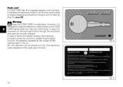
... to disable "engine block" function -immediately signalled by the orange EOBD warning light (7, fig. 4). In case of engine disabled and therefore if engine will not start up after the key-ON. However, it is advisable to keep the electronic code printed on the CODE CARD handy when...Warning Keep the CODE CARD in case it indicates the electronic code (A, fig. 9) to be carried out only if the electronic code indicated on the code card is known. Code card A CODE CARD (fig. 8) is supplied together with the keys, it is necessary to remove engine block through the procedure that uses the throttle...
... to disable "engine block" function -immediately signalled by the orange EOBD warning light (7, fig. 4). In case of engine disabled and therefore if engine will not start up after the key-ON. However, it is advisable to keep the electronic code printed on the CODE CARD handy when...Warning Keep the CODE CARD in case it indicates the electronic code (A, fig. 9) to be carried out only if the electronic code indicated on the code card is known. Code card A CODE CARD (fig. 8) is supplied together with the keys, it is necessary to remove engine block through the procedure that uses the throttle...
Owners Manual
Page 106
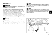
... the safety sensor (2) at the same time, lift the thrust arm (1) with your foot until the side stand is possible to the right and, at regular intervals. Note It is resting on the thrust arm (1) with its rest position (horizontal position), tilt the motorcycle to start the engine with a gear engaged, pull the clutch lever (in neutral. Do not park on soft...
... the safety sensor (2) at the same time, lift the thrust arm (1) with your foot until the side stand is possible to the right and, at regular intervals. Note It is resting on the thrust arm (1) with its rest position (horizontal position), tilt the motorcycle to start the engine with a gear engaged, pull the clutch lever (in neutral. Do not park on soft...

Owners Manual
Page 112
... riding, perform a thorough check-up if needed (page 40). Brake and clutch fluid Check fluid level in the relevant reservoirs. Tyre condition Check tyre pressure and condition (page 58). Failure to rider and passenger. from any burnt-out bulbs (page 53). Lights and indicators Make sure lights, indicators and horn work properly. Key-operated locks Check that fuel filler plug and seat catch locks are closed firmly. E 35 Replace any liability...
... riding, perform a thorough check-up if needed (page 40). Brake and clutch fluid Check fluid level in the relevant reservoirs. Tyre condition Check tyre pressure and condition (page 58). Failure to rider and passenger. from any burnt-out bulbs (page 53). Lights and indicators Make sure lights, indicators and horn work properly. Key-operated locks Check that fuel filler plug and seat catch locks are closed firmly. E 35 Replace any liability...
Owners Manual
Page 113
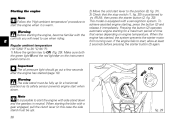
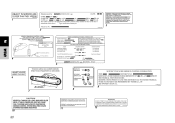
... the green light N and the red light on the instrument panel come on engine temperature. Pressing the button (2) operates automatic engine starting the bike with a gear engaged, pull the clutch lever (in this case the side stand must be up (in neutral. This model is positioned to ON (fig. 29). Warning The side stand must be fully up ). 36 E 2) Move the cold start lever to...
... the green light N and the red light on the instrument panel come on engine temperature. Pressing the button (2) operates automatic engine starting the bike with a gear engaged, pull the clutch lever (in this case the side stand must be up (in neutral. This model is positioned to ON (fig. 29). Warning The side stand must be fully up ). 36 E 2) Move the cold start lever to...

Owners Manual
Page 116
..., shift down to engine-brake first and then brake applying both brake lever and pedal for effective braking. Braking Slow down in time, shift down gears to use brake controls harshly or violently or you less braking power. Apply one of the brakes will become less effective. E 39 When riding in a bend. Any sudden manoeuvres may lock the wheels and lose control of control. Always use brakes sparingly. Pull the clutch...
..., shift down to engine-brake first and then brake applying both brake lever and pedal for effective braking. Braking Slow down in time, shift down gears to use brake controls harshly or violently or you less braking power. Apply one of the brakes will become less effective. E 39 When riding in a bend. Any sudden manoeuvres may lock the wheels and lose control of control. Always use brakes sparingly. Pull the clutch...
Owners Manual
Page 130
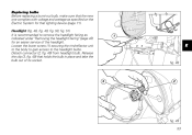
... headlight bulb. Release the clip (3, fig. 49) that holds the bulb in place and take the bulb out of the headlight. Loosen the lower screw (1) securing the rim/reflector unit to the body to gain access to remove the headlight fairing as specified on the Electric System for an easier service of its socket. 1 E fig. 48 3 2 fig. 49 53 Replacing bulbs Before replacing a burnt-out bulb...
... headlight bulb. Release the clip (3, fig. 49) that holds the bulb in place and take the bulb out of the headlight. Loosen the lower screw (1) securing the rim/reflector unit to the body to gain access to remove the headlight fairing as specified on the Electric System for an easier service of its socket. 1 E fig. 48 3 2 fig. 49 53 Replacing bulbs Before replacing a burnt-out bulb...

Owners Manual
Page 135
... pressure on bumpy roads, increase tyre pressure by temperature and altitude variations, you are advised to keep air inside. Tyre repair or replacement In the event of the wheels. To avoid front wheel rim distortion, when riding on one tyre, check the tyre for punctures. Important Do not remove or shift the wheel balancing weights. Tyres Front tyre pressure: 2.1 bar - 2.3 Kg/sq. cm Rear tyre pressure: 2.2 bar...
... pressure on bumpy roads, increase tyre pressure by temperature and altitude variations, you are advised to keep air inside. Tyre repair or replacement In the event of the wheels. To avoid front wheel rim distortion, when riding on one tyre, check the tyre for punctures. Important Do not remove or shift the wheel balancing weights. Tyres Front tyre pressure: 2.1 bar - 2.3 Kg/sq. cm Rear tyre pressure: 2.2 bar...
Owners Manual
Page 140
... empty the fuel tank; have any parts not in compliance with the standards in force in use of the vehicle after such device or element of design has been removed or rendered inoperative by hand a few drops of engine oil into the cylinders through the spark plug seats, then crank the engine by any new vehicle for purposes of maintenance, repair or replacement, of...
... empty the fuel tank; have any parts not in compliance with the standards in force in use of the vehicle after such device or element of design has been removed or rendered inoperative by hand a few drops of engine oil into the cylinders through the spark plug seats, then crank the engine by any new vehicle for purposes of maintenance, repair or replacement, of...
Owners Manual
Page 147
... frame with upper section made of the shock absorber. The swingarm hinges on certain technical specifications, do not perform any service operation that might change them. Note Homologation depends on a pivot pin passing through the engine. Size: 120/70-ZR17 70 Steering angle (on each side): 27° Steering head angle: 24° Trail mm: 96 Rear Tubeless, radial tyre.
... frame with upper section made of the shock absorber. The swingarm hinges on certain technical specifications, do not perform any service operation that might change them. Note Homologation depends on a pivot pin passing through the engine. Size: 120/70-ZR17 70 Steering angle (on each side): 27° Steering head angle: 24° Trail mm: 96 Rear Tubeless, radial tyre.
Owners Manual
Page 149
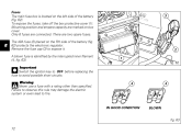
... fuse cap (3) to avoid possible short circuits. A blown fuse is located on the left side of the battery (fig. 62) protects the electronic regulator. To expose the fuses, take off the box protective cover (1). There are connected. Warning Never use a fuse with a rating other than specified. Fuses The main fuse box is identified by the interrupted inner filament (4, fig. 63). Important Switch the ignition key...
... fuse cap (3) to avoid possible short circuits. A blown fuse is located on the left side of the battery (fig. 62) protects the electronic regulator. To expose the fuses, take off the box protective cover (1). There are connected. Warning Never use a fuse with a rating other than specified. Fuses The main fuse box is identified by the interrupted inner filament (4, fig. 63). Important Switch the ignition key...
Owners Manual
Page 150
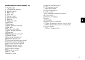
... Starter motor 7) Solenoid starter 8) Battery 9) Regulator fuse 10)Regulator. 11)Generator. 12)Rear right turn indicator. 13)Tail light. 14)Number plate light. 15)Rear left turn indicator. 16)Fuel tank. 17)Self-diagnosis connector 18)Speed sensor 19)Horizontal cylinder coil 20)Vertical cylinder coil 21)Horizontal cylinder spark plug 1. 22)Vertical cylinder spark plug 1. 23)Horizontal cylinder injector 24)Vertical cylinder injector 25)Throttle position sensor 26)Timing/rpm sensor 27)Side stand switch. 28)ECU 5.9 M. 29)Injection relay 30)Neutral indicator switch. 31)Oil pressure switch 32)Rear...
... Starter motor 7) Solenoid starter 8) Battery 9) Regulator fuse 10)Regulator. 11)Generator. 12)Rear right turn indicator. 13)Tail light. 14)Number plate light. 15)Rear left turn indicator. 16)Fuel tank. 17)Self-diagnosis connector 18)Speed sensor 19)Horizontal cylinder coil 20)Vertical cylinder coil 21)Horizontal cylinder spark plug 1. 22)Vertical cylinder spark plug 1. 23)Horizontal cylinder injector 24)Vertical cylinder injector 25)Throttle position sensor 26)Timing/rpm sensor 27)Side stand switch. 28)ECU 5.9 M. 29)Injection relay 30)Neutral indicator switch. 31)Oil pressure switch 32)Rear...

Owners Manual
Page 153
... equipped with parts other than for the purpose of noise control prior to its sale or delivery to penalties under state and local ordinances. Problems that may become subject to the ultimate purchaser or while it is separate from the throttle body and fuel tank. Rough idle. The Exhaust Emission Control System is in use . Poor performance (driveability) and poor economy. 76
... equipped with parts other than for the purpose of noise control prior to its sale or delivery to penalties under state and local ordinances. Problems that may become subject to the ultimate purchaser or while it is separate from the throttle body and fuel tank. Rough idle. The Exhaust Emission Control System is in use . Poor performance (driveability) and poor economy. 76
Owners Manual
Page 154
... speed limit or drive too fast for proper operation of both the front and rear brakes. Operate motorcycle only at all conditions. Warning Before starting engine, check for existing conditions. A motorcycle does not provide the impact protection of power to skid and lose control. When going down , and grip the fuel tank with its operation and handling characteristics under these conditions. Use the front and rear brakes...
... speed limit or drive too fast for proper operation of both the front and rear brakes. Operate motorcycle only at all conditions. Warning Before starting engine, check for existing conditions. A motorcycle does not provide the impact protection of power to skid and lose control. When going down , and grip the fuel tank with its operation and handling characteristics under these conditions. Use the front and rear brakes...
Owners Manual
Page 157
... Federal Motor Vehicle Safety standards in & ex): See Service Manual Closing 0.03 - 0.12 mm SPARK PLUG: CHAMPION RA4HC SPARK PLUG GAP (mm): 0.5 0.6 OIL: SAE 20W50 FUEL: Unleaded gasoline INSTRUCTIONS No adjustment No adjustment No adjustment HOT AIR INLET HOLDING Via A.C.Ducati,3 40132 BOLOGNA ITALY CANISTER ITEM IGNITION TIMING: IDLE SPEED (RPM): IDLE MIXTURE: TO HORIZONTAL MANIFOLD TO VERTICAL MANIFOLD 4 5 HOLDING - No.: Z D M 1 T B 9 P X W B 0 0 0 0 0 1 Cod. 432 1 234 1A WARNING YOUR DUCATI MOTORCYCLE IS EQUIPPED WITH A WARNING LIGHT...
... Federal Motor Vehicle Safety standards in & ex): See Service Manual Closing 0.03 - 0.12 mm SPARK PLUG: CHAMPION RA4HC SPARK PLUG GAP (mm): 0.5 0.6 OIL: SAE 20W50 FUEL: Unleaded gasoline INSTRUCTIONS No adjustment No adjustment No adjustment HOT AIR INLET HOLDING Via A.C.Ducati,3 40132 BOLOGNA ITALY CANISTER ITEM IGNITION TIMING: IDLE SPEED (RPM): IDLE MIXTURE: TO HORIZONTAL MANIFOLD TO VERTICAL MANIFOLD 4 5 HOLDING - No.: Z D M 1 T B 9 P X W B 0 0 0 0 0 1 Cod. 432 1 234 1A WARNING YOUR DUCATI MOTORCYCLE IS EQUIPPED WITH A WARNING LIGHT...
Owners Manual
Page 158
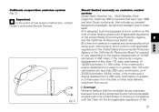
... a headlight, tail-light and stoplight, and is street legal: A) is less than 280 cubic centimeters; C Coverage Warranty defects shall be remedied during customary business hours at the time of initial retail purchase with the Clean Air Act and applicable regulations of the United States Environmental Protection Agency, and the California Air Resources Board; of fuel system malfunction, contact Ducati's authorized Service...
... a headlight, tail-light and stoplight, and is street legal: A) is less than 280 cubic centimeters; C Coverage Warranty defects shall be remedied during customary business hours at the time of initial retail purchase with the Clean Air Act and applicable regulations of the United States Environmental Protection Agency, and the California Air Resources Board; of fuel system malfunction, contact Ducati's authorized Service...
Owners Manual
Page 159
...; fuel/vapor separator; ignition coils; II. B. Any motorcycle on Ducati's recommended time allowance for any of Ducati under this Emission Control Systems Warranty is not complete within 30 days. ignition wires; III. intake manifold; air cutoff valves; Any replacement part can be liable for the warranty repair and the geographically appropriate hourly labor rate. These warranted parts are specifically defined by that actual mileage cannot be performed by an authorized Ducati motorcycle...
...; fuel/vapor separator; ignition coils; II. B. Any motorcycle on Ducati's recommended time allowance for any of Ducati under this Emission Control Systems Warranty is not complete within 30 days. ignition wires; III. intake manifold; air cutoff valves; Any replacement part can be liable for the warranty repair and the geographically appropriate hourly labor rate. These warranted parts are specifically defined by that actual mileage cannot be performed by an authorized Ducati motorcycle...