

Owners Manual
Page 5
warnings 18 Vehicle ID number 20 Engine ID number 21 Plate positioning 22 Noise and exhaust emission control system information 26 33 Table of Contents California emission control warranty statement 26 Your warranty rights and obligations 26 Manufacturer's warranty coverage 27 Owner's warranty responsibilities: 27 California evaporation emission system 28 Ducati limited warranty on emission control system 29 Introduction 7 Instrument Panel (Dashboard) Display settings and functions 33 Acronyms and...
warnings 18 Vehicle ID number 20 Engine ID number 21 Plate positioning 22 Noise and exhaust emission control system information 26 33 Table of Contents California emission control warranty statement 26 Your warranty rights and obligations 26 Manufacturer's warranty coverage 27 Owner's warranty responsibilities: 27 California evaporation emission system 28 Ducati limited warranty on emission control system 29 Introduction 7 Instrument Panel (Dashboard) Display settings and functions 33 Acronyms and...
Owners Manual
Page 6
Trip meter 2 (TRIP 2) 80 Partial fuel reserve counter (TRIP FUEL) 81 LAP time 82 Engine coolant temperature 85 Instantaneous fuel consumption 87 Average fuel consumption 88 Average speed 90 Trip time 91 External air temperature 92 Clock 93 Auxiliary functions 94 Service warning (SERVICE) 96 OIL SERVICE zero warning 97 OIL SERVICE or DESMO SERVICE countdown indication 98 OIL SERVICE or DESMO SERVICE indication 99 Warning/Alarm (Warning) 100 Error warnings 104 Displayed errors description 106 Viewing...
Trip meter 2 (TRIP 2) 80 Partial fuel reserve counter (TRIP FUEL) 81 LAP time 82 Engine coolant temperature 85 Instantaneous fuel consumption 87 Average fuel consumption 88 Average speed 90 Trip time 91 External air temperature 92 Clock 93 Auxiliary functions 94 Service warning (SERVICE) 96 OIL SERVICE zero warning 97 OIL SERVICE or DESMO SERVICE countdown indication 98 OIL SERVICE or DESMO SERVICE indication 99 Warning/Alarm (Warning) 100 Error warnings 104 Displayed errors description 106 Viewing...

Owners Manual
Page 7
... switch 187 Throttle twistgrip 188 Front brake lever 189 Rear brake pedal 190 Gear change pedal 191 Adjusting the position of the gearchange and rear brake pedals 192 Pre-ride checks 216 Starting the engine 219 Moving off 221 Braking 222 Stopping the motorcycle 224 Refueling 225 Parking 226 Tool kit and accessories 227 Main components and devices Position on the vehicle 194 Tank filler plug 195 Seat lock 196 Seat...
... switch 187 Throttle twistgrip 188 Front brake lever 189 Rear brake pedal 190 Gear change pedal 191 Adjusting the position of the gearchange and rear brake pedals 192 Pre-ride checks 216 Starting the engine 219 Moving off 221 Braking 222 Stopping the motorcycle 224 Refueling 225 Parking 226 Tool kit and accessories 227 Main components and devices Position on the vehicle 194 Tank filler plug 195 Seat lock 196 Seat...
Owners Manual
Page 8
... Wheels 277 Tires 277 Suspensions 277 Exhaust system 278 Available colors 278 Electrical system 279 Maintenance 264 Scheduled maintenance chart: operations to be performed by the Dealer 264 Scheduled maintenance chart: operations to be performed by the customer 267 Routine maintenance record Routine maintenance record 285 285 Technical data 268 Weights 268 Overall dimensions 269 Top-ups 270 Engine 272 Timing system 273 Performance data 274 Spark plugs 274 Fuel system 274 Brakes 275 Transmission...
... Wheels 277 Tires 277 Suspensions 277 Exhaust system 278 Available colors 278 Electrical system 279 Maintenance 264 Scheduled maintenance chart: operations to be performed by the Dealer 264 Scheduled maintenance chart: operations to be performed by the customer 267 Routine maintenance record Routine maintenance record 285 285 Technical data 268 Weights 268 Overall dimensions 269 Top-ups 270 Engine 272 Timing system 273 Performance data 274 Spark plugs 274 Fuel system 274 Brakes 275 Transmission...

Owners Manual
Page 28
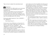
...). Exhaust Emission Control System Exhaust Emission Control System is controlled by an Electronic Control Unit (ECU), and no adjustments should be made except idle speed adjustments with an evaporative emission control system which consists of the following symptoms, have the vehicle inspected and repaired by gas is separate from the engine and fuel tank. Problems that may affect motorcycle emissions If you are equipped with the throttle...
...). Exhaust Emission Control System Exhaust Emission Control System is controlled by an Electronic Control Unit (ECU), and no adjustments should be made except idle speed adjustments with an evaporative emission control system which consists of the following symptoms, have the vehicle inspected and repaired by gas is separate from the engine and fuel tank. Problems that may affect motorcycle emissions If you are equipped with the throttle...
Owners Manual
Page 29
.... Where a warrantable condition exists, Ducati North America, Inc. You are responsible for presenting your motorcycle to abuse, neglect, improper maintenance or unapproved modifications. - Owner's warranty responsibilities: As the motorcycle owner, you warranty coverage if your owner's manual. must be completed in your motorcycle or a part has failed due to a Ducati dealer as soon as fuel-injection system, the ignition system, catalytic converter, and engine computer.
.... Where a warrantable condition exists, Ducati North America, Inc. You are responsible for presenting your motorcycle to abuse, neglect, improper maintenance or unapproved modifications. - Owner's warranty responsibilities: As the motorcycle owner, you warranty coverage if your owner's manual. must be completed in your motorcycle or a part has failed due to a Ducati dealer as soon as fuel-injection system, the ignition system, catalytic converter, and engine computer.
Owners Manual
Page 31
.... fuel tank cap for a period of use of 18,641 miles (30,000 kilometers) or 5 (five) years from the date of initial retail delivery, whichever first occurs. ignition coils; ignition points, condensers, and spark plugs if failure occurs prior to model, certain models may not contain all applicable regulations of the United States Environmental Protection Agency, and the California Air Resources Board; intake manifold; In...
.... fuel tank cap for a period of use of 18,641 miles (30,000 kilometers) or 5 (five) years from the date of initial retail delivery, whichever first occurs. ignition coils; ignition points, condensers, and spark plugs if failure occurs prior to model, certain models may not contain all applicable regulations of the United States Environmental Protection Agency, and the California Air Resources Board; intake manifold; In...
Owners Manual
Page 76
... sensitivity level Attention The levels of the ABS system your vehicle. If tires of a different size class are recommended to ensure a very stable braking, good lift-up control. Tips on the following parameters: 1) 2) The tire/asphalt grip (type of tire, amount of tire wear, the road/track surface, weather conditions, etc.). Motorcycle original equipment: (front 120/70ZR17 rear 190/55ZR17). Selecting level 3, the...
... sensitivity level Attention The levels of the ABS system your vehicle. If tires of a different size class are recommended to ensure a very stable braking, good lift-up control. Tips on the following parameters: 1) 2) The tire/asphalt grip (type of tire, amount of tire wear, the road/track surface, weather conditions, etc.). Motorcycle original equipment: (front 120/70ZR17 rear 190/55ZR17). Selecting level 3, the...
Owners Manual
Page 94
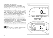
... the instrument panel is not receiving air temperature value, a string of three steady dashes "- -" is displayed followed by the unit of measurement, the EOBD light will show three flashing dashes " - - If the air temperature sensor is displayed. " as air temperature value, followed by the unit of three steady dashes " - - - The temperature value is stopped, the engine heat may influence the displayed temperature. 3 2 1 4 SPORT SENSOR T-AIR 0 T AIR km/h DTC 2 ABS...
... the instrument panel is not receiving air temperature value, a string of three steady dashes "- -" is displayed followed by the unit of measurement, the EOBD light will show three flashing dashes " - - If the air temperature sensor is displayed. " as air temperature value, followed by the unit of three steady dashes " - - - The temperature value is stopped, the engine heat may influence the displayed temperature. 3 2 1 4 SPORT SENSOR T-AIR 0 T AIR km/h DTC 2 ABS...
Owners Manual
Page 109
... Ignition coil malfunction Injector malfunction Engine rpm sensor malfunction Lambda sensor or Lambda sensor heater malfunction Vehicle starting relay malfunction Secondary air sensor malfunction FUEL SENSOR SPEED SENSOR BATTERY STOP LIGHT FAN SIDE STAND T-AIR DDA SPEED Reserve NTC sensor malfunction Front and/or rear speed sensor malfunction Battery voltage too high or too low Stop light not working Electric cooling fan malfunction Side stand sensor malfunction Ambient air temperature sensor DDA control unit does not work properly Front and rear speed sensor malfunction Note "FAN...
... Ignition coil malfunction Injector malfunction Engine rpm sensor malfunction Lambda sensor or Lambda sensor heater malfunction Vehicle starting relay malfunction Secondary air sensor malfunction FUEL SENSOR SPEED SENSOR BATTERY STOP LIGHT FAN SIDE STAND T-AIR DDA SPEED Reserve NTC sensor malfunction Front and/or rear speed sensor malfunction Battery voltage too high or too low Stop light not working Electric cooling fan malfunction Side stand sensor malfunction Ambient air temperature sensor DDA control unit does not work properly Front and rear speed sensor malfunction Note "FAN...

Owners Manual
Page 174
... current consumption from the battery, by managing headlight switching-on and off automatically when starting the engine (with engine running the standard operation of the lights is restored: it is still possible to turn on the low/high beam by pressing button (1) in position (B). At Key-On, the high beam and low beam lights are off, only the parking lights are turned off the high...
... current consumption from the battery, by managing headlight switching-on and off automatically when starting the engine (with engine running the standard operation of the lights is restored: it is still possible to turn on the low/high beam by pressing button (1) in position (B). At Key-On, the high beam and low beam lights are off, only the parking lights are turned off the high...
Owners Manual
Page 177
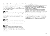
... changed at each ignition key is an electronic device that inhibits engine operation whenever the ignition switch is turned off automatically in the battery while the function is active, the instrument panel will not be possible to normal operation of each start if it will disable the function when the voltage is equipped with an IMMOBILIZER, an electronic system that modulates an output signal...
... changed at each ignition key is an electronic device that inhibits engine operation whenever the ignition switch is turned off automatically in the battery while the function is active, the instrument panel will not be possible to normal operation of each start if it will disable the function when the voltage is equipped with an IMMOBILIZER, an electronic system that modulates an output signal...
Owners Manual
Page 225
... brake at a time and use the brakes very gently and carefully when riding under these conditions. using the two brake controls separately reduces the motorcycle braking efficiency. Any sudden maneuvers may lock the wheels and lose control of control. Never use engine braking. When riding in a bend. 223 When tackling long, high-gradient downhill road tracts, shift down gears to overheat and reduce braking power dangerously. Keeping the brakes...
... brake at a time and use the brakes very gently and carefully when riding under these conditions. using the two brake controls separately reduces the motorcycle braking efficiency. Any sudden maneuvers may lock the wheels and lose control of control. Never use engine braking. When riding in a bend. 223 When tackling long, high-gradient downhill road tracts, shift down gears to overheat and reduce braking power dangerously. Keeping the brakes...
Owners Manual
Page 231
... and brake pads are still in the Warranty Booklet; Attention Clutch fluid level will increase as you note too much play on the respective reservoirs. Change the air filter Important Have the air filter maintenance performed at the intervals specified in the scheduled maintenance table contained in good condition, contact your Ducati Dealer or Authorized Service Center to have the system inspected and air drained out. Important All brake and clutch...
... and brake pads are still in the Warranty Booklet; Attention Clutch fluid level will increase as you note too much play on the respective reservoirs. Change the air filter Important Have the air filter maintenance performed at the intervals specified in the scheduled maintenance table contained in good condition, contact your Ducati Dealer or Authorized Service Center to have the system inspected and air drained out. Important All brake and clutch...

Owners Manual
Page 267
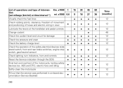
... of final drive front and rear sprocket nuts Check final drive (chain, front and rear sprocket) and sliding shoes wear Check final drive chain tension and lubrication Check steering bearings and lubricate, if necessary Change front fork fluid Visually check the front fork and rear shock absorber seals Check the freedom of movement and tightening of intervention [set mileage (km/mi) or time interval *] Km...
... of final drive front and rear sprocket nuts Check final drive (chain, front and rear sprocket) and sliding shoes wear Check final drive chain tension and lubrication Check steering bearings and lubricate, if necessary Change front fork fluid Visually check the front fork and rear shock absorber seals Check the freedom of movement and tightening of intervention [set mileage (km/mi) or time interval *] Km...
Owners Manual
Page 268
.... ABS and DTC), electric fans and idling Softly clean the motorcycle Fill out that the service was performed in view Lubricate the levers at the handlebar and pedal controls Change coolant Check the coolant level and circuit for damage Check tire pressure and wear Check the battery charge level Check the operation of the safety electrical devices (side stand switch, front and rear brake switches, engine stop switch, gear/neutral sensor) Check lighting, turn indicators, horn and controls...
.... ABS and DTC), electric fans and idling Softly clean the motorcycle Fill out that the service was performed in view Lubricate the levers at the handlebar and pedal controls Change coolant Check the coolant level and circuit for damage Check tire pressure and wear Check the battery charge level Check the operation of the safety electrical devices (side stand switch, front and rear brake switches, engine stop switch, gear/neutral sensor) Check lighting, turn indicators, horn and controls...
Owners Manual
Page 269
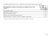
If necessary, contact your dealer to be performed by the customer List of operations and type of intervention [set interval, whichever comes first (mileage or months) Km. Scheduled maintenance chart: operations to replace pads * Service on the set mileage (km/mi) or time interval *] Check engine oil level Check brake and clutch fluid level Check tire pressure and wear Check the drive chain tension and lubrication Check brake pads. x1000 mi. x1000 Months 1 0.6 6 267
If necessary, contact your dealer to be performed by the customer List of operations and type of intervention [set interval, whichever comes first (mileage or months) Km. Scheduled maintenance chart: operations to replace pads * Service on the set mileage (km/mi) or time interval *] Check engine oil level Check brake and clutch fluid level Check tire pressure and wear Check the drive chain tension and lubrication Check brake pads. x1000 mi. x1000 Months 1 0.6 6 267

Owners Manual
Page 275
This system is driven by eight rocker arms (four opening and four closing ones) and two overhead camshafts. closing (or lower) rocker; camshaft; return spring for lower rocker; closing (or lower) rocker shim; valve. 273 opening rocker shim; Timing system DESMODROMIC system with four valves per cylinder controlled by the crankshaft through spur gears, pulleys and toothed belts. 6 2 1 3 2 5 1 4 2 5 7 Fig 191 Desmodromic timing system 1) 2) 3) 4) 5) 6) 7) opening (or upper) rocker;
This system is driven by eight rocker arms (four opening and four closing ones) and two overhead camshafts. closing (or lower) rocker; camshaft; return spring for lower rocker; closing (or lower) rocker shim; valve. 273 opening rocker shim; Timing system DESMODROMIC system with four valves per cylinder controlled by the crankshaft through spur gears, pulleys and toothed belts. 6 2 1 3 2 5 1 4 2 5 7 Fig 191 Desmodromic timing system 1) 2) 3) 4) 5) 6) 7) opening (or upper) rocker;
Owners Manual
Page 284
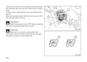
H L G E Important Switch the ignition key to OFF before replacing the fuse to reach them. Remove the fuse cap (E) on solenoid starter (D). The two main fuses (C) are two fuses: a 25 A (G) fuse and a 30 A (H) one. Failure to observe this rule may damage the electric system or even cause fire. A blown fuse is identified by the interrupted center link (F). C D Fig 194 Attention Never use a fuse with a rating other than specified. Near the solenoid starter there are located on both fuses to avoid possible short-circuits. F F Fig 195 282
H L G E Important Switch the ignition key to OFF before replacing the fuse to reach them. Remove the fuse cap (E) on solenoid starter (D). The two main fuses (C) are two fuses: a 25 A (G) fuse and a 30 A (H) one. Failure to observe this rule may damage the electric system or even cause fire. A blown fuse is identified by the interrupted center link (F). C D Fig 194 Attention Never use a fuse with a rating other than specified. Near the solenoid starter there are located on both fuses to avoid possible short-circuits. F F Fig 195 282
Owners Manual
Page 285
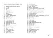
...) Ignition system (ignition switch) LH fan RH fan Generator Regulator Solenoid starter Battery Wiring ground Exhaust valve actuator ABS control unit Front fuse box Rear fuse box Front speed sensor Rear speed sensor Self-diagnosis/DDA Rear right turn indicator Rear light Rear left turn indicator Number plate light BBS Alarm (optional) Oil pressure sensor Gear sensor Side stand switch 25) 26) 27) 28) 29) 30) 31) 32) 33) 34) 35) 36) 37) 38) 39) 40) 41) 42) 43) 44) 45) 46) 47) 48) 49) 50) Clutch switch Timing...
...) Ignition system (ignition switch) LH fan RH fan Generator Regulator Solenoid starter Battery Wiring ground Exhaust valve actuator ABS control unit Front fuse box Rear fuse box Front speed sensor Rear speed sensor Self-diagnosis/DDA Rear right turn indicator Rear light Rear left turn indicator Number plate light BBS Alarm (optional) Oil pressure sensor Gear sensor Side stand switch 25) 26) 27) 28) 29) 30) 31) 32) 33) 34) 35) 36) 37) 38) 39) 40) 41) 42) 43) 44) 45) 46) 47) 48) 49) 50) Clutch switch Timing...