

Owners Manual
Page 7
... PARTS ...LOADING AND ACCESSORIES INFORMATION ...GENERAL INFORMATION ...Meter Instruments ...Digital Meter ...Warning/Indicator Lights ...Key ...Ignition Switch/Steering Lock ...Left Handlebar Switches ...Dimmer Switch ...Turn Signal Switch...Horn Button ...Right Handlebar Switches...Engine Stop Switch ...Starter Button ...Brake Lever Adjuster...Fuel Tank Cap ...7 11 12 15 18 18 19 25 27 29 31 31 32 32 32 32 33 33 34 Fuel Tank ...Fuel Requirement ...Side Stand ...Seats ...Tool Kit ...Air Cleaner Intake ...Meter Unit Mounting Angle...Rear View Mirror ...BREAK-IN ...HOW...
... PARTS ...LOADING AND ACCESSORIES INFORMATION ...GENERAL INFORMATION ...Meter Instruments ...Digital Meter ...Warning/Indicator Lights ...Key ...Ignition Switch/Steering Lock ...Left Handlebar Switches ...Dimmer Switch ...Turn Signal Switch...Horn Button ...Right Handlebar Switches...Engine Stop Switch ...Starter Button ...Brake Lever Adjuster...Fuel Tank Cap ...7 11 12 15 18 18 19 25 27 29 31 31 32 32 32 32 33 33 34 Fuel Tank ...Fuel Requirement ...Side Stand ...Seats ...Tool Kit ...Air Cleaner Intake ...Meter Unit Mounting Angle...Rear View Mirror ...BREAK-IN ...HOW...

Owners Manual
Page 8
... Maintenance Chart...Engine Oil ...Cooling System ...Spark Plugs...Evaporative Emission Control System (California model only)...Valve Clearance ...Kawasaki Clean Air System ...Exhaust Device ...Air Cleaner ...Throttle Control System ...Engine Vacuum Synchronization ...Idle Speed ...Clutch ... 67 67 70 73 75 80 91 97 103 104 105 106 107 108 109 112 112 114 Drive Chain ...Brakes ...Brake Light Switches...Front Fork...Rear Shock Absorber...Wheels ...Battery...Headlight Beam...Fuses ...General Lubrication...Cleaning Your Motorcycle ...Bolt and Nut Tightening...STORAGE ...TROUBLESHOOTING GUIDE...
... Maintenance Chart...Engine Oil ...Cooling System ...Spark Plugs...Evaporative Emission Control System (California model only)...Valve Clearance ...Kawasaki Clean Air System ...Exhaust Device ...Air Cleaner ...Throttle Control System ...Engine Vacuum Synchronization ...Idle Speed ...Clutch ... 67 67 70 73 75 80 91 97 103 104 105 106 107 108 109 112 112 114 Drive Chain ...Brakes ...Brake Light Switches...Front Fork...Rear Shock Absorber...Wheels ...Battery...Headlight Beam...Fuses ...General Lubrication...Cleaning Your Motorcycle ...Bolt and Nut Tightening...STORAGE ...TROUBLESHOOTING GUIDE...

Owners Manual
Page 14
Clutch Lever Left Handlebar Switches Spring Preload Adjuster Rebound Damping Force Adjuster Meter Instruments 6. 7. 8. 9. 10. Brake Fluid Reservoir (Front) Right Handlebar Switches Front Brake Lever Throttle Grip Ignition Switch/Steering Lock 12 LOCATION OF PARTS LOCATION OF PARTS 1. 2. 3. 4. 5.
Clutch Lever Left Handlebar Switches Spring Preload Adjuster Rebound Damping Force Adjuster Meter Instruments 6. 7. 8. 9. 10. Brake Fluid Reservoir (Front) Right Handlebar Switches Front Brake Lever Throttle Grip Ignition Switch/Steering Lock 12 LOCATION OF PARTS LOCATION OF PARTS 1. 2. 3. 4. 5.

Owners Manual
Page 16
Fuse Box Battery Fuel Tank Cap Muffler Brake Fluid Reservoir (Rear) Swingarm Rebound Damping Force Adjuster 38. 39. 40. 41. 42. 43. 14 LOCATION OF PARTS 31. 32. 33. 34. 35. 36. 37. Rear Shock Absorber Rear Brake Light Switch Rear Brake Pedal Oil Level Gauge Oil Filter Coolant Reserve Tank
Fuse Box Battery Fuel Tank Cap Muffler Brake Fluid Reservoir (Rear) Swingarm Rebound Damping Force Adjuster 38. 39. 40. 41. 42. 43. 14 LOCATION OF PARTS 31. 32. 33. 34. 35. 36. 37. Rear Shock Absorber Rear Brake Light Switch Rear Brake Pedal Oil Level Gauge Oil Filter Coolant Reserve Tank

Owners Manual
Page 19
... also due to the handlebar or front fork will not be used to tow any other large items have not adversely affected any lighting components, road clearance, banking capability (i.e., lean angle), control operation, wheel travel, front fork movement, or any trailers or other vehicles. Weight attached to the aerodynamic force acting on these surfaces while the motorcycle is...
... also due to the handlebar or front fork will not be used to tow any other large items have not adversely affected any lighting components, road clearance, banking capability (i.e., lean angle), control operation, wheel travel, front fork movement, or any trailers or other vehicles. Weight attached to the aerodynamic force acting on these surfaces while the motorcycle is...

Owners Manual
Page 25
... and the trip meter AB. D. A. Odometer The odometer shows the total distance in kilometers or miles that the vehicle has been ridden. C. B. Odometer Trip Meter A Trip Meter B Push Left Button GENERAL INFORMATION 23 żThe clock works normally by the back NOTE -up power while the ignition switch is turned off. żWhen the battery is disconnected, the clock...
... and the trip meter AB. D. A. Odometer The odometer shows the total distance in kilometers or miles that the vehicle has been ridden. C. B. Odometer Trip Meter A Trip Meter B Push Left Button GENERAL INFORMATION 23 żThe clock works normally by the back NOTE -up power while the ignition switch is turned off. żWhen the battery is disconnected, the clock...

Owners Manual
Page 26
...0.0, and then starts counting when the vehicle is operated. The lowest segment and fuel żThe data is maintained even if the battery is disconnected. żWhen the figures come to 999999, they are displayed. 24 GENERAL INFORMATION NOTE NOTE -up power if the ignition key is turned off. ż...is full, all the segments are stopped and locked. When the fuel tank is maintained by the number of segments displayed. Trip Meters AB The trip meter shows the distance in the fuel tank is next reset. Fuel Gauge The fuel in kilometers or miles traveled since it is shown by the back...
...0.0, and then starts counting when the vehicle is operated. The lowest segment and fuel żThe data is maintained even if the battery is disconnected. żWhen the figures come to 999999, they are displayed. 24 GENERAL INFORMATION NOTE NOTE -up power if the ignition key is turned off. ż...is full, all the segments are stopped and locked. When the fuel tank is maintained by the number of segments displayed. Trip Meters AB The trip meter shows the distance in the fuel tank is next reset. Fuel Gauge The fuel in kilometers or miles traveled since it is shown by the back...

Owners Manual
Page 36
Insert the ignition key into place with the key inserted. Adjuster B. NOTE A. The key can be locked. Mark żThe fuel tank cap cannot be closed without the key inserted, and the key cannot be removed unless the cap is locked properly. żDo not push on the key to close the cap, push it to the left to the right. To close the cap, or the cap cannot be removed by turning it down into the fuel tank cap and turn the key to the original position. 34 GENERAL INFORMATION Fuel Tank Cap To open the fuel tank cap, pull up the key hole cover.
Insert the ignition key into place with the key inserted. Adjuster B. NOTE A. The key can be locked. Mark żThe fuel tank cap cannot be closed without the key inserted, and the key cannot be removed unless the cap is locked properly. żDo not push on the key to close the cap, push it to the left to the right. To close the cap, or the cap cannot be removed by turning it down into the fuel tank cap and turn the key to the original position. 34 GENERAL INFORMATION Fuel Tank Cap To open the fuel tank cap, pull up the key hole cover.
Owners Manual
Page 38
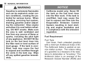
... under certain conditions, creating the potential for serious burns. The octane rating of a gasoline is overfilled, heat may cause the fuel to cool before refueling. When refueling, servicing fuel system, draining gasoline and/or adjusting the carburetor: Stop engine and allow it to expand and flow into the filler neck. 36 GENERAL INFORMATION WARNING Gasoline is posted on service station pumps.
... under certain conditions, creating the potential for serious burns. The octane rating of a gasoline is overfilled, heat may cause the fuel to cool before refueling. When refueling, servicing fuel system, draining gasoline and/or adjusting the carburetor: Stop engine and allow it to expand and flow into the filler neck. 36 GENERAL INFORMATION WARNING Gasoline is posted on service station pumps.

Owners Manual
Page 45
Tads C. Rider's Seat B. Holes Insert the projections on the rear of the rider's seat into the holes on the frame and tighten the bolts. • • Passenger's Seat Installation Insert the tab on the rear of the passenger's seat into the slots in the frame. Slots D. Projections E. GENERAL INFORMATION 43 Rider's Seat Installation Insert the tabs on the front of the rider's seat into the slot in the frame. Insert the projections at the front of the passenger's seat into the holes on the frame. • • A.
Tads C. Rider's Seat B. Holes Insert the projections on the rear of the rider's seat into the holes on the frame and tighten the bolts. • • Passenger's Seat Installation Insert the tab on the rear of the passenger's seat into the slots in the frame. Slots D. Projections E. GENERAL INFORMATION 43 Rider's Seat Installation Insert the tabs on the front of the rider's seat into the slot in the frame. Insert the projections at the front of the passenger's seat into the holes on the frame. • • A.

Owners Manual
Page 61
...; 2nd 2nd ĺ 1st km/h (mph) 30 (19) 25 (15) 20 (12) 15 ( 9) 15 ( 9) NOTE żThe transmission is standing still, the transmission cannot be shifted past neutral from 1st gear. HOW TO RIDE THE MOTORCYCLE 59 Vehicle speed when shifting Shifting up 1st ĺ 2nd 2nd ĺ 3rd 3rd ĺ 4th 4th ĺ 5th 5th ĺ 6th km...
...; 2nd 2nd ĺ 1st km/h (mph) 30 (19) 25 (15) 20 (12) 15 ( 9) 15 ( 9) NOTE żThe transmission is standing still, the transmission cannot be shifted past neutral from 1st gear. HOW TO RIDE THE MOTORCYCLE 59 Vehicle speed when shifting Shifting up 1st ĺ 2nd 2nd ĺ 3rd 3rd ĺ 4th 4th ĺ 5th 5th ĺ 6th km...

Owners Manual
Page 73
...;, 42 psi) Install the air valve cap. Steering ...Action smooth but not loose from lock to lock. No brake fluid leakage. Coolant ...No coolant leakage. Drive Chain ...Slack 20 a 30 mm (0.8 a 1.2 in .) left. Clutch ...Clutch lever play 2 a 3 mm (0.08 a 0.12 in .). Electrical Equipment ...All lights (Headlight, Tail/Brake Lights, Turn Signal Lights, Licence Plate Light, Warning/Indicator Lights) and horn work. Steering Damper Unit: No oil leakage. Nuts, Bolts, Fasteners Check that steering and suspension components, axles, and all controls are properly tightened or fastened...
...;, 42 psi) Install the air valve cap. Steering ...Action smooth but not loose from lock to lock. No brake fluid leakage. Coolant ...No coolant leakage. Drive Chain ...Slack 20 a 30 mm (0.8 a 1.2 in .) left. Clutch ...Clutch lever play 2 a 3 mm (0.08 a 0.12 in .). Electrical Equipment ...All lights (Headlight, Tail/Brake Lights, Turn Signal Lights, Licence Plate Light, Warning/Indicator Lights) and horn work. Steering Damper Unit: No oil leakage. Nuts, Bolts, Fasteners Check that steering and suspension components, axles, and all controls are properly tightened or fastened...

Owners Manual
Page 75
... properly. Coolant: To avoid overheating, check that the headlight, tail/brake light, turn signal lights, license plate light horn, etc., all safety related parts are crucial for riding safety. Electrical Equipment: Make sure that the coolant level is hard on tires, and good tires are in the steering can cause loss of control. Examine their overall condition, inflate them to see that all work properly. Steering: Looseness in good condition. Engine Oil: To avoid engine seizure...
... properly. Coolant: To avoid overheating, check that the headlight, tail/brake light, turn signal lights, license plate light horn, etc., all safety related parts are crucial for riding safety. Electrical Equipment: Make sure that the coolant level is hard on tires, and good tires are in the steering can cause loss of control. Examine their overall condition, inflate them to see that all work properly. Steering: Looseness in good condition. Engine Oil: To avoid engine seizure...

Owners Manual
Page 88
... operation (damping and smooth stroke) inspect Front forks/rear shock absorber oil leak - 86 MAINTENANCE AND ADJUSTMENT Frequency Whichever comes first *Odometer Reading km × 1 000 (mile × 1 000) See Page Operation (Chassis Items) Brake operation (effectiveness, play, drag) - inspect Brake light switch operation - inspect Every year 1 6 12 18 24 30 36 (0.6) (3.75) (7.5) (11.25) (15) (18.75) (22.5) •...
... operation (damping and smooth stroke) inspect Front forks/rear shock absorber oil leak - 86 MAINTENANCE AND ADJUSTMENT Frequency Whichever comes first *Odometer Reading km × 1 000 (mile × 1 000) See Page Operation (Chassis Items) Brake operation (effectiveness, play, drag) - inspect Brake light switch operation - inspect Every year 1 6 12 18 24 30 36 (0.6) (3.75) (7.5) (11.25) (15) (18.75) (22.5) •...

Owners Manual
Page 93
This fills the oil filter with the Periodic Maintenance Chart. MAINTENANCE AND ADJUSTMENT 91 Engine Oil In order for the engine, transmission, and clutch to function properly, maintain the engine oil at idle speed. the motorcycle has just been used too long. Oil Level Inspection If the oil has just been changed, start the engine and run it for all the oil to the periodic maintenance chart in engine or transmission seizure, accident, and...
This fills the oil filter with the Periodic Maintenance Chart. MAINTENANCE AND ADJUSTMENT 91 Engine Oil In order for the engine, transmission, and clutch to function properly, maintain the engine oil at idle speed. the motorcycle has just been used too long. Oil Level Inspection If the oil has just been changed, start the engine and run it for all the oil to the periodic maintenance chart in engine or transmission seizure, accident, and...

Owners Manual
Page 126
... rear wheel to inspect the • Rotate drive chain for unevenly or excessively worn teeth, and damaged teeth. Good Teeth B. See Service Manual for installation; Lubrication Lubrication is exaggerated for illustration. there is an endless type and should not be cut for wear limits. Worn Teeth C. A. It is any time that the chain appears dry. 124 MAINTENANCE AND ADJUSTMENT WARNING...
... rear wheel to inspect the • Rotate drive chain for unevenly or excessively worn teeth, and damaged teeth. Good Teeth B. See Service Manual for installation; Lubrication Lubrication is exaggerated for illustration. there is an endless type and should not be cut for wear limits. Worn Teeth C. A. It is any time that the chain appears dry. 124 MAINTENANCE AND ADJUSTMENT WARNING...

Owners Manual
Page 132
Inspection Turn the ignition key to inspect the front brake light switch. If it does not, adjust the rear brake • If light switch. The brake light should go on after the proper pedal travel. • • • A. The brake light should be adjusted in accordance with the Periodic Maintenance Chart. 130 MAINTENANCE AND ADJUSTMENT Brake Light Switches When either the front or rear brake is applied. the operation of the rear brake •...
Inspection Turn the ignition key to inspect the front brake light switch. If it does not, adjust the rear brake • If light switch. The brake light should go on after the proper pedal travel. • • • A. The brake light should be adjusted in accordance with the Periodic Maintenance Chart. 130 MAINTENANCE AND ADJUSTMENT Brake Light Switches When either the front or rear brake is applied. the operation of the rear brake •...

Owners Manual
Page 154
... from the center of the headlight, with the motorcycle on its wheels and the rider seated. This is 0.4 degrees below horizontal. If not properly adjusted horizontally, the beam will point to illuminate the road close ahead, and the low beam will blind oncoming drivers. 152 MAINTENANCE AND ADJUSTMENT move the headlight beam upward, • To turn the both adjusters...
... from the center of the headlight, with the motorcycle on its wheels and the rider seated. This is 0.4 degrees below horizontal. If not properly adjusted horizontally, the beam will point to illuminate the road close ahead, and the low beam will blind oncoming drivers. 152 MAINTENANCE AND ADJUSTMENT move the headlight beam upward, • To turn the both adjusters...

Owners Manual
Page 165
Engine Mounting Bolts and Nuts 8. Rear Frame Mounting Bolts 9. Caliper Mounting Bolts 13. Rear Axle Nut 19. Swingarm Pivot Shaft Nut 16. Footpeg Mounting Bolt 17. Brake Disc Mounting Bolts 10. Front Axle Clamp Bolt 11. Uni-trak Tie-Rod Nuts 15. Front Axle Nut 12. Front Fender Mounting Bolts 7. MAINTENANCE AND ADJUSTMENT 163 6. Rear Sprocket Nuts Rear Shock Absorber Mounting Bolts 18. Side Stand Bolt 14.
Engine Mounting Bolts and Nuts 8. Rear Frame Mounting Bolts 9. Caliper Mounting Bolts 13. Rear Axle Nut 19. Swingarm Pivot Shaft Nut 16. Footpeg Mounting Bolt 17. Brake Disc Mounting Bolts 10. Front Axle Clamp Bolt 11. Uni-trak Tie-Rod Nuts 15. Front Axle Nut 12. Front Fender Mounting Bolts 7. MAINTENANCE AND ADJUSTMENT 163 6. Rear Sprocket Nuts Rear Shock Absorber Mounting Bolts 18. Side Stand Bolt 14.

Owners Manual
Page 184
Noise Emission Control Information Weight and Manufacture Vehicle Emission Control Information Vacuum Hose Routing Diagram *: only on California model 182 LOCATION OF LABELS 5. 6. *7. *8.
Noise Emission Control Information Weight and Manufacture Vehicle Emission Control Information Vacuum Hose Routing Diagram *: only on California model 182 LOCATION OF LABELS 5. 6. *7. *8.