

Owners Manual
Page 8
... ...Meter Instruments ...Speedometer and Tachometer ...Fuel Gauge ...Warning/Indicator Lights ...Key ...Ignition Switch/Steering Lock ...Right Handlebar Switches...Engine Stop Switch: ...Starter Button: ...Left Handlebar Switches ...Dimmer Switch: ...Turn Signal Switch:...Horn Button: ...Fuel Tank Cap ...8 12 13 16 19 22 22 23 23 23 25 27 28 28 29 30 30 31 31 31 Fuel Tank ...Fuel Tap ...Stand...Seats ...Helmet Hooks...Tool Kit ...Tying Hooks ...BREAK-IN ...HOW TO RIDE THE MOTORCYCLE . Starting the Engine ...Jump Starting ...Moving Off...Shifting Gears ...Braking...
... ...Meter Instruments ...Speedometer and Tachometer ...Fuel Gauge ...Warning/Indicator Lights ...Key ...Ignition Switch/Steering Lock ...Right Handlebar Switches...Engine Stop Switch: ...Starter Button: ...Left Handlebar Switches ...Dimmer Switch: ...Turn Signal Switch:...Horn Button: ...Fuel Tank Cap ...8 12 13 16 19 22 22 23 23 23 25 27 28 28 29 30 30 31 31 31 Fuel Tank ...Fuel Tap ...Stand...Seats ...Helmet Hooks...Tool Kit ...Tying Hooks ...BREAK-IN ...HOW TO RIDE THE MOTORCYCLE . Starting the Engine ...Jump Starting ...Moving Off...Shifting Gears ...Braking...

Owners Manual
Page 9
... Periodic Maintenance Chart...Engine Oil ...Cooling System ...Spark Plugs...Evaporative Emission Control System (California model only)...Kawasaki Clean Air System ...Valve Clearance ...Air Cleaner ...Throttle Control System ...Choke Lever...Carburetors ...Clutch ...Drive Chain ... 63 66 69 71 76 88 94 100 101 102 103 104 108 110 111 113 115 Brakes ...Brake Light Switches...Front Fork...Rear Shock Absorbers ...Wheels ...Battery...Headlight Beam...Fuses ...General Lubrication...Cleaning Your Motorcycle ...Bolt and Nut Tightening...STORAGE ...TROUBLESHOOTING GUIDE...YOUR WARRANTY/OWNER...
... Periodic Maintenance Chart...Engine Oil ...Cooling System ...Spark Plugs...Evaporative Emission Control System (California model only)...Kawasaki Clean Air System ...Valve Clearance ...Air Cleaner ...Throttle Control System ...Choke Lever...Carburetors ...Clutch ...Drive Chain ... 63 66 69 71 76 88 94 100 101 102 103 104 108 110 111 113 115 Brakes ...Brake Light Switches...Front Fork...Rear Shock Absorbers ...Wheels ...Battery...Headlight Beam...Fuses ...General Lubrication...Cleaning Your Motorcycle ...Bolt and Nut Tightening...STORAGE ...TROUBLESHOOTING GUIDE...YOUR WARRANTY/OWNER...

Owners Manual
Page 23
... handling of the motorcycle, not only because of their weight, but can only warn that Kawasaki cannot assume responsibility for motorcycles and cannot predict the effects of such accessories on motorcycle components caused by the use of the steering assembly and can result in an unsafe riding condition. 9. Maximum Load Weight of the motorcycle's operation. 7. Fairings, windshields, backrests, and other vehicle. Kawasaki...
... handling of the motorcycle, not only because of their weight, but can only warn that Kawasaki cannot assume responsibility for motorcycles and cannot predict the effects of such accessories on motorcycle components caused by the use of the steering assembly and can result in an unsafe riding condition. 9. Maximum Load Weight of the motorcycle's operation. 7. Fairings, windshields, backrests, and other vehicle. Kawasaki...
Owners Manual
Page 26
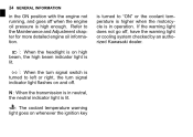
... for more detailed engine oil information. : When the headlight is high enough. N : When the transmission is in neutral, the neutral indicator light is lit. : The coolant temperature warning light goes on whenever the ignition key is turned to left or right, the turn signal indicator light flashes on high beam, the high beam indicator light is lit. : When the turn signal switch is turned to "ON" or the coolant temperature is higher...
... for more detailed engine oil information. : When the headlight is high enough. N : When the transmission is in neutral, the neutral indicator light is lit. : The coolant temperature warning light goes on whenever the ignition key is turned to left or right, the turn signal indicator light flashes on high beam, the high beam indicator light is lit. : When the turn signal switch is turned to "ON" or the coolant temperature is higher...

Owners Manual
Page 29
... OFF or LOCK position. To avoid battery discharge, always start the engine immediately after starting the engine. GENERAL INFORMATION 27 Ignition Switch/Steering Lock This is released after turning the ignition key to "ON". Engine on when the starter button is a three-position, key-operated switch. For locking push down the key in the ON position. OFF ON LOCK Engine off . Steering locked. One headlight goes on . Turn the handlebar fully to Lock position. The key can be...
... OFF or LOCK position. To avoid battery discharge, always start the engine immediately after starting the engine. GENERAL INFORMATION 27 Ignition Switch/Steering Lock This is released after turning the ignition key to "ON". Engine on when the starter button is a three-position, key-operated switch. For locking push down the key in the ON position. OFF ON LOCK Engine off . Steering locked. One headlight goes on . Turn the handlebar fully to Lock position. The key can be...

Owners Manual
Page 33
Fuel Tank Cap To open the fuel tank cap, pull up the key hole cover. GENERAL INFORMATION 31 Turn Signal Switch: When the turn signal flashes on and off. To stop flashing, push the switch in. Horn Button: When the horn button is locked properly. The key can be removed unless the cap is pushed, the horn sounds. To close the cap, push it to the right. Insert the ignition key into place with...
Fuel Tank Cap To open the fuel tank cap, pull up the key hole cover. GENERAL INFORMATION 31 Turn Signal Switch: When the turn signal flashes on and off. To stop flashing, push the switch in. Horn Button: When the horn button is locked properly. The key can be removed unless the cap is pushed, the horn sounds. To close the cap, push it to the right. Insert the ignition key into place with...

Owners Manual
Page 34
Fuel Tank Cap A. Tank Cap Fuel Tank Top Level Filler Neck Ignition Key C. D. B. C. 32 GENERAL INFORMATION NOTE Fuel Tank Avoid filling the tank in the rain or where heavy dust is blowing so that the fuel does not get contaminated. żDo not push on the key to close the cap, or the cap cannot be locked. A. Key Hole Cover B.
Fuel Tank Cap A. Tank Cap Fuel Tank Top Level Filler Neck Ignition Key C. D. B. C. 32 GENERAL INFORMATION NOTE Fuel Tank Avoid filling the tank in the rain or where heavy dust is blowing so that the fuel does not get contaminated. żDo not push on the key to close the cap, or the cap cannot be locked. A. Key Hole Cover B.

Owners Manual
Page 35
... vents in hard starting and engine hesitation. If the tank is well ventilated and free from any appliance with a minimum Antiknock Index of 87. After refueling, make sure the tank cap is an average of flame or sparks; Never fill the tank completely to detonation or "knocking." NOTICE California models only: Never fill the tank so the fuel level rises into...
... vents in hard starting and engine hesitation. If the tank is well ventilated and free from any appliance with a minimum Antiknock Index of 87. After refueling, make sure the tank cap is an average of flame or sparks; Never fill the tank completely to detonation or "knocking." NOTICE California models only: Never fill the tank so the fuel level rises into...

Owners Manual
Page 43
B. D. A. Rider's Seat Tabs Slots Insert C. Insert the projection at the front of the passenger's seat into the slot on the frame and tighten the bolts. • the left and right side covers • Install and tighten bolts. • • Passenger's Seat Insert the tab of the bracket into the slot in the rear of the rider's seat into the slots on the frame. GENERAL INFORMATION 41 Rider's Seat Insert the tabs on the rear of the passenger's seat.
B. D. A. Rider's Seat Tabs Slots Insert C. Insert the projection at the front of the passenger's seat into the slot on the frame and tighten the bolts. • the left and right side covers • Install and tighten bolts. • • Passenger's Seat Insert the tab of the bracket into the slot in the rear of the rider's seat into the slots on the frame. GENERAL INFORMATION 41 Rider's Seat Insert the tabs on the rear of the passenger's seat.
Owners Manual
Page 58
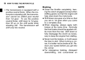
... equipped with a positive neutral finder. The transmission will cause • Never the tires to 1st gear, then lift up on • the throttle completely, leav• Close ing the clutch engaged (except when • • shifting gears) so that you are in 1st gear when you get into neutral. When stopping, always apply both brakes at a time so that the engine will help slow...
... equipped with a positive neutral finder. The transmission will cause • Never the tires to 1st gear, then lift up on • the throttle completely, leav• Close ing the clutch engaged (except when • • shifting gears) so that you are in 1st gear when you get into neutral. When stopping, always apply both brakes at a time so that the engine will help slow...

Owners Manual
Page 64
... conditions unburned air/fuel mixture flowing out of the catalytic converter. 62 HOW TO RIDE THE MOTORCYCLE WARNING The muffler and exhaust pipe are very hot while the engine is cold. This can ignite a fire, resulting in the converter allowing the converter to overheat and become damaged when the engine is hot, or reduces converter performance when the engine is running and just after the engine stops. Do not idle or park...
... conditions unburned air/fuel mixture flowing out of the catalytic converter. 62 HOW TO RIDE THE MOTORCYCLE WARNING The muffler and exhaust pipe are very hot while the engine is cold. This can ignite a fire, resulting in the converter allowing the converter to overheat and become damaged when the engine is hot, or reduces converter performance when the engine is running and just after the engine stops. Do not idle or park...

Owners Manual
Page 69
... that steering and suspension components, axles, and all controls are properly tightened or fastened. Engine oil ...Oil level between level lines (when engine is cold). Nuts, bolts, fasteners .. Steering ...Action smooth but not loose from lock to 170 kg (375 lb) 225 kPa (2.25 kg/cm², 32 psi) Load Install the air valve cap. Coolant level between level lines. No brake fluid leakage. Clutch lever operates smoothly. Throttle ...Throttle grip...
... that steering and suspension components, axles, and all controls are properly tightened or fastened. Engine oil ...Oil level between level lines (when engine is cold). Nuts, bolts, fasteners .. Steering ...Action smooth but not loose from lock to 170 kg (375 lb) 225 kPa (2.25 kg/cm², 32 psi) Load Install the air valve cap. Coolant level between level lines. No brake fluid leakage. Clutch lever operates smoothly. Throttle ...Throttle grip...

Owners Manual
Page 71
.... Fuel: Have sufficient fuel for the high fuel consumption during high speed operation, cannot be overemphasized. Check to see that the headlight, tail/brake light, turn signals, horn, etc., all work properly. Engine Oil: To avoid engine seizure and resulting loss of control, make sure that the coolant level is at the upper level line. Coolant: To avoid overheating, check that the oil level is at the upper level line. Electrical...
.... Fuel: Have sufficient fuel for the high fuel consumption during high speed operation, cannot be overemphasized. Check to see that the headlight, tail/brake light, turn signals, horn, etc., all work properly. Engine Oil: To avoid engine seizure and resulting loss of control, make sure that the coolant level is at the upper level line. Coolant: To avoid overheating, check that the oil level is at the upper level line. Electrical...

Owners Manual
Page 84
82 MAINTENANCE AND ADJUSTMENT Frequency Whichever comes first *Odometer Reading km × 1000 (mile × 1000) See Page 1 (0.6) 6 (3.75) 12 18 24 30 36 (7.5) (11.25) (15) (18.75) (22.5) Operation (Chassis Items) Brake operation (effectiveness, play, drag) inspect Brake light switch operation - inspect Suspensions: Front forks/rear shock absorber operation (damping and smooth stroke) inspect Every year • • • • • • • • • • • • • • • • • 127 128 130/131
82 MAINTENANCE AND ADJUSTMENT Frequency Whichever comes first *Odometer Reading km × 1000 (mile × 1000) See Page 1 (0.6) 6 (3.75) 12 18 24 30 36 (7.5) (11.25) (15) (18.75) (22.5) Operation (Chassis Items) Brake operation (effectiveness, play, drag) inspect Brake light switch operation - inspect Suspensions: Front forks/rear shock absorber operation (damping and smooth stroke) inspect Every year • • • • • • • • • • • • • • • • • 127 128 130/131
Owners Manual
Page 90
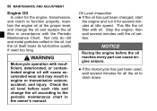
... can cause engine seizure. 88 MAINTENANCE AND ADJUSTMENT Engine Oil In order for the engine, transmission, and clutch to function properly, maintain the engine oil at idle speed. Oil Level Inspection If the oil has just been changed, start the engine and run it for several minutes until the oil settles. • NOTICE Racing the engine before each ride and change the oil and replace the oil filter in the oil, but the oil itself loses...
... can cause engine seizure. 88 MAINTENANCE AND ADJUSTMENT Engine Oil In order for the engine, transmission, and clutch to function properly, maintain the engine oil at idle speed. Oil Level Inspection If the oil has just been changed, start the engine and run it for several minutes until the oil settles. • NOTICE Racing the engine before each ride and change the oil and replace the oil filter in the oil, but the oil itself loses...

Owners Manual
Page 94
... the filter mounting bolt, fit the fil- Install the oil filter, tightening its mounting bolt to the specified torque. NOTE żReplace any gasket with a good quality engine oil the engine. • Start the oil level and for it is not available, this item should be serviced by a Kawasaki dealer. After the oil has completely drained out, install the engine oil drain plug with a new gasket. 92 MAINTENANCE AND ADJUSTMENT a little engine oil to...
... the filter mounting bolt, fit the fil- Install the oil filter, tightening its mounting bolt to the specified torque. NOTE żReplace any gasket with a good quality engine oil the engine. • Start the oil level and for it is not available, this item should be serviced by a Kawasaki dealer. After the oil has completely drained out, install the engine oil drain plug with a new gasket. 92 MAINTENANCE AND ADJUSTMENT a little engine oil to...

Owners Manual
Page 123
...have the • If drive chain and/or the sprockets replaced by an authorized Kawasaki dealer. Also inspect the sprockets for illustration. Worn Teeth C. the rear wheel to inspect the • Rotate drive chain for damaged rollers, and ...NOTE żSprocket wear is exaggerated for unevenly or excessively worn teeth, and damaged teeth. It is any irregularity, have it installed by an authorized Kawasaki dealer. Good Teeth B. MAINTENANCE AND ADJUSTMENT 121 WARNING For safety, use only the standard chain...
...have the • If drive chain and/or the sprockets replaced by an authorized Kawasaki dealer. Also inspect the sprockets for illustration. Worn Teeth C. the rear wheel to inspect the • Rotate drive chain for damaged rollers, and ...NOTE żSprocket wear is exaggerated for unevenly or excessively worn teeth, and damaged teeth. It is any irregularity, have it installed by an authorized Kawasaki dealer. Good Teeth B. MAINTENANCE AND ADJUSTMENT 121 WARNING For safety, use only the standard chain...

Owners Manual
Page 130
Inspection Turn the ignition key to inspect the front brake light switch. Pedal Travel it does not, ask your authorized Kawasaki dealer to "ON". the operation of the rear brake • Check light switch by depressing the brake pedal. Brake Pedal Travel 10 mm (0.4 in accordance with the Periodic Maintenance Chart. The brake light should go on when the front brake is applied, the brake light goes on. If it...
Inspection Turn the ignition key to inspect the front brake light switch. Pedal Travel it does not, ask your authorized Kawasaki dealer to "ON". the operation of the rear brake • Check light switch by depressing the brake pedal. Brake Pedal Travel 10 mm (0.4 in accordance with the Periodic Maintenance Chart. The brake light should go on when the front brake is applied, the brake light goes on. If it...

Owners Manual
Page 131
D. C. NOTICE To avoid damaging the electrical connections inside the switch, be sure that the switch body does not turn during adjustment. • A. B. Rear Brake Light Switch Adjusting Nut Lights sooner Lights later MAINTENANCE AND ADJUSTMENT 129 Adjustment To adjust the rear brake light switch, move the switch up or down by turning the switch body.
D. C. NOTICE To avoid damaging the electrical connections inside the switch, be sure that the switch body does not turn during adjustment. • A. B. Rear Brake Light Switch Adjusting Nut Lights sooner Lights later MAINTENANCE AND ADJUSTMENT 129 Adjustment To adjust the rear brake light switch, move the switch up or down by turning the switch body.

Owners Manual
Page 158
156 MAINTENANCE AND ADJUSTMENT 10. Front Axle Nut 11. Brake Disk Mounting Bolts 15. Brake Pedal Mounting Bolt 18. Rear Axle Nut 14. Caliper Mounting Bolts 13. Rear Master Cylinder Mounting Bolts 16. Front Brake Master Cylinder Clamp Bolt 12. Rear Shock Absorber Mounting Nuts 17. UNI TRACK Lever Rod Nuts
156 MAINTENANCE AND ADJUSTMENT 10. Front Axle Nut 11. Brake Disk Mounting Bolts 15. Brake Pedal Mounting Bolt 18. Rear Axle Nut 14. Caliper Mounting Bolts 13. Rear Master Cylinder Mounting Bolts 16. Front Brake Master Cylinder Clamp Bolt 12. Rear Shock Absorber Mounting Nuts 17. UNI TRACK Lever Rod Nuts