
Owners Manual
Page 8
... Gauge: ...Key ...Ignition Switch/Steering Lock ...Right Handlebar Switches...Engine Stop Switch: ...Starter Button: ...Left Handlebar Switches ...Dimmer Switch: ...Turn Signal Switch:...8 12 13 16 19 19 20 20 20 20 25 27 29 30 30 31 32 32 33 Horn Button: ...Hazard Switch: ...Brake/Clutch Lever Adjusters...Fuel Tank Cap ...Fuel Tank ...Fuel Requirement: ...Stand...Seat ...Helmet Holding Cable ...Tool Kit/U-Shaped Lock Compartment ...Tying Hooks ...BREAK-IN ...HOW TO RIDE THE MOTORCYCLE . Starting the Engine ...Jump Starting ...Moving Off...Shifting Gears ...Braking...
... Gauge: ...Key ...Ignition Switch/Steering Lock ...Right Handlebar Switches...Engine Stop Switch: ...Starter Button: ...Left Handlebar Switches ...Dimmer Switch: ...Turn Signal Switch:...8 12 13 16 19 19 20 20 20 20 25 27 29 30 30 31 32 32 33 Horn Button: ...Hazard Switch: ...Brake/Clutch Lever Adjusters...Fuel Tank Cap ...Fuel Tank ...Fuel Requirement: ...Stand...Seat ...Helmet Holding Cable ...Tool Kit/U-Shaped Lock Compartment ...Tying Hooks ...BREAK-IN ...HOW TO RIDE THE MOTORCYCLE . Starting the Engine ...Jump Starting ...Moving Off...Shifting Gears ...Braking...

Owners Manual
Page 9
... Maintenance Chart...Engine Oil ...Cooling System ...Spark Plugs...Evaporative Emission Control System (California model only)...Kawasaki Clean Air System ...Valve Clearance ...Air Cleaner ...Throttle Control System ...Engine Vacuum Synchronization ...Idle Speed ... 59 60 62 64 64 67 70 72 77 87 93 99 100 101 102 103 104 107 108 Clutch ...Drive Chain ...Brakes ...Brake Light Switches...Front Fork...Rear Shock Absorbers ...Wheels ...Battery...Headlight Beam...Fuses ...General Lubrication...Cleaning Your Motorcycle ...Bolt and Nut Tightening...STORAGE ...TROUBLESHOOTING GUIDE...YOUR WARRANTY...
... Maintenance Chart...Engine Oil ...Cooling System ...Spark Plugs...Evaporative Emission Control System (California model only)...Kawasaki Clean Air System ...Valve Clearance ...Air Cleaner ...Throttle Control System ...Engine Vacuum Synchronization ...Idle Speed ... 59 60 62 64 64 67 70 72 77 87 93 99 100 101 102 103 104 107 108 Clutch ...Drive Chain ...Brakes ...Brake Light Switches...Front Fork...Rear Shock Absorbers ...Wheels ...Battery...Headlight Beam...Fuses ...General Lubrication...Cleaning Your Motorcycle ...Bolt and Nut Tightening...STORAGE ...TROUBLESHOOTING GUIDE...YOUR WARRANTY...

Owners Manual
Page 15
Right Handlebar Switches Front Brake Lever Throttle Grip Ignition Switch/Steering Lock LOCATION OF PARTS 13 LOCATION OF PARTS 1. 2. 3. 4. Clutch Lever Left Handlebar Switches Meter Instruments Brake Fluid Reservoir (Front) 5. 6. 7. 8.
Right Handlebar Switches Front Brake Lever Throttle Grip Ignition Switch/Steering Lock LOCATION OF PARTS 13 LOCATION OF PARTS 1. 2. 3. 4. Clutch Lever Left Handlebar Switches Meter Instruments Brake Fluid Reservoir (Front) 5. 6. 7. 8.

Owners Manual
Page 17
Muffler 32. Oil Level Gauge 35. Spring Preload Adjuster 37. LOCATION OF PARTS 15 26. Rear Shock Absorber 36. Coolant Reserve Tank Fuel Tank 30. Tail/Brake Light 28. Brake Fluid Reservoir (Rear) 29. Idle Adjusting Screw 38. Fuel Tank Cap 31. Rear Brake Pedal 34. License Plate Light 27. Rear Brake Light Switch 33.
Muffler 32. Oil Level Gauge 35. Spring Preload Adjuster 37. LOCATION OF PARTS 15 26. Rear Shock Absorber 36. Coolant Reserve Tank Fuel Tank 30. Tail/Brake Light 28. Brake Fluid Reservoir (Rear) 29. Idle Adjusting Screw 38. Fuel Tank Cap 31. Rear Brake Pedal 34. License Plate Light 27. Rear Brake Light Switch 33.

Owners Manual
Page 20
... under warranty. Fairings, windshields, backrests, and other vehicle. Weight attached to the handlebar or front fork will not be used to the aerodynamic forces acting on motorcycle components caused by the use of the steering assembly and can result in operation. Kawasaki does not manufacture sidecars or trailers for motorcycles and cannot predict the effects of such accessories on handling...
... under warranty. Fairings, windshields, backrests, and other vehicle. Weight attached to the handlebar or front fork will not be used to the aerodynamic forces acting on motorcycle components caused by the use of the steering assembly and can result in operation. Kawasaki does not manufacture sidecars or trailers for motorcycles and cannot predict the effects of such accessories on handling...

Owners Manual
Page 24
...; After turns to local regulations is correctly displayed before riding. Make sure that km/h or mph according to 0.0, and then starts counting when the vehicle is operated. Km/h·Mph Display: Km/h·Mph Display can alternate between metric and English modes (km/h not operate the vehicle with the... the battery is next reset. Shift the km/h·mph display in . km/h·mph Display A. the odometer. • Display The km/h·mph display shifts by the back żDo -up power if the ignition key is turned off. żWhen the trip meter is reset while the vehicle is ...
...; After turns to local regulations is correctly displayed before riding. Make sure that km/h or mph according to 0.0, and then starts counting when the vehicle is operated. Km/h·Mph Display: Km/h·Mph Display can alternate between metric and English modes (km/h not operate the vehicle with the... the battery is next reset. Shift the km/h·mph display in . km/h·mph Display A. the odometer. • Display The km/h·mph display shifts by the back żDo -up power if the ignition key is turned off. żWhen the trip meter is reset while the vehicle is ...

Owners Manual
Page 26
The displays stop flashing and the clock starts working again when the battery is disconnected, the clock resets to 1:00 and starts working . clock works normally from the back-up power while the ignition switch is turned off. żWhen the battery is connected. • ing again. Push the MODE button. NOTE żPushing the MODE button momentarily advances the hour or minute step by step. Pushing and holding the button advances the hour or minute continuously. 24 GENERAL INFORMATION żThe the RESET button. Both the • Push hour and minute displays start flash-
The displays stop flashing and the clock starts working again when the battery is disconnected, the clock resets to 1:00 and starts working . clock works normally from the back-up power while the ignition switch is turned off. żWhen the battery is connected. • ing again. Push the MODE button. NOTE żPushing the MODE button momentarily advances the hour or minute step by step. Pushing and holding the button advances the hour or minute continuously. 24 GENERAL INFORMATION żThe the RESET button. Both the • Push hour and minute displays start flash-

Owners Manual
Page 31
... lights A. One headlight goes on and turn signals can be removed from the switch when it is in the OFF, LOCK, or P (Park) position. Engine off . To avoid battery discharge, always start the engine immediately after starting the engine. GENERAL INFORMATION 29 Ignition Switch/Steering Lock This is released after turning the ignition key to "ON". All electrical equipment can be used . Steering locked. All electrical circuits off . License plate, tail, and city lights on when the starter...
... lights A. One headlight goes on and turn signals can be removed from the switch when it is in the OFF, LOCK, or P (Park) position. Engine off . To avoid battery discharge, always start the engine immediately after starting the engine. GENERAL INFORMATION 29 Ignition Switch/Steering Lock This is released after turning the ignition key to "ON". All electrical equipment can be used . Steering locked. All electrical circuits off . License plate, tail, and city lights on when the starter...

Owners Manual
Page 37
Key Hole Cover B. Ignition Key C. The key can be removed by turning it down into the fuel tank cap and turn the key to close the cap, push it to the left to the original position. A. GENERAL INFORMATION 35 Fuel Tank Cap To open the fuel tank cap, pull up the key hole cover. To close the cap, or the cap cannot be removed unless the cap is locked properly. żDo not push on...
Key Hole Cover B. Ignition Key C. The key can be removed by turning it down into the fuel tank cap and turn the key to close the cap, push it to the left to the original position. A. GENERAL INFORMATION 35 Fuel Tank Cap To open the fuel tank cap, pull up the key hole cover. To close the cap, or the cap cannot be removed unless the cap is locked properly. żDo not push on...

Owners Manual
Page 58
To use the positive neutral finder, shift down to 1st gear, then lift up 1st ĺ 2nd 2nd ĺ 3rd 3rd ĺ 4th 4th ĺ 5th 5th ĺ 6th km/h (mph) 15 ( 9) 25 (15) 35 (21) 45 (27) 55 (34) Shifting down 6th ĺ 5th 5th ĺ ... 25 (15) 20 (12) 15 ( 9) 15 ( 9) NOTE żThe transmission is standing still, the transmission cannot be shifted past neutral from 1st gear. The transmission will shift only into neutral. 56 HOW TO RIDE THE MOTORCYCLE Vehicle speed when shifting Shifting up on the shift pedal while standing still. When the motorcycle is equipped with a positive...
To use the positive neutral finder, shift down to 1st gear, then lift up 1st ĺ 2nd 2nd ĺ 3rd 3rd ĺ 4th 4th ĺ 5th 5th ĺ 6th km/h (mph) 15 ( 9) 25 (15) 35 (21) 45 (27) 55 (34) Shifting down 6th ĺ 5th 5th ĺ ... 25 (15) 20 (12) 15 ( 9) 15 ( 9) NOTE żThe transmission is standing still, the transmission cannot be shifted past neutral from 1st gear. The transmission will shift only into neutral. 56 HOW TO RIDE THE MOTORCYCLE Vehicle speed when shifting Shifting up on the shift pedal while standing still. When the motorcycle is equipped with a positive...

Owners Manual
Page 70
...) Load Install the air valve cap. Throttle ...Throttle grip play 2 ∼ 3 mm (0.08 ∼ 0.12 in .). Clutch ...Clutch lever play 2 ∼ 3 mm (0.08 ∼ 0.12 in .). Drive chain ...Slack 25 ∼ 35 mm (1.0 ∼ 1.4 in .) left. Nuts, bolts, fasteners .. No binding of control cables. Electrical equipment ...All lights (Headlight, Tail/Brake Lights, Turn Signal Lights, Warning/Indicator Lights) and horn work. Coolant ...No coolant leakage. Clutch lever operates smoothly. Coolant level between level lines (when engine is cold). Brakes ...Brake pad wear: Lining...
...) Load Install the air valve cap. Throttle ...Throttle grip play 2 ∼ 3 mm (0.08 ∼ 0.12 in .). Clutch ...Clutch lever play 2 ∼ 3 mm (0.08 ∼ 0.12 in .). Drive chain ...Slack 25 ∼ 35 mm (1.0 ∼ 1.4 in .) left. Nuts, bolts, fasteners .. No binding of control cables. Electrical equipment ...All lights (Headlight, Tail/Brake Lights, Turn Signal Lights, Warning/Indicator Lights) and horn work. Coolant ...No coolant leakage. Clutch lever operates smoothly. Coolant level between level lines (when engine is cold). Brakes ...Brake pad wear: Lining...

Owners Manual
Page 72
... the headlight, tail/brake light, turn signals, horn, etc., all nuts and bolts are in the steering can cause loss of the brakes, especially during high speed operation. Engine Oil: To avoid engine seizure and resulting loss of control, make sure that they are crucial for riding safety. Steering: Looseness in good condition. Fuel: Have sufficient fuel for High Speed Operation Brakes: The importance of control. Check to the proper pressure, and check the wheel...
... the headlight, tail/brake light, turn signals, horn, etc., all nuts and bolts are in the steering can cause loss of the brakes, especially during high speed operation. Engine Oil: To avoid engine seizure and resulting loss of control, make sure that they are crucial for riding safety. Steering: Looseness in good condition. Fuel: Have sufficient fuel for High Speed Operation Brakes: The importance of control. Check to the proper pressure, and check the wheel...

Owners Manual
Page 84
... year • • • • • • 123 125 126 128,129 year • 128,129 inspect Front forks/rear shock absorber oil leak - 82 MAINTENANCE AND ADJUSTMENT Frequency Whichever comes first Every *Odometer Reading See km × 1000 ( mile × 1000) Page Operation (Chassis Items) Brake fluid level - inspect Suspensions: Front forks/rear shock absorber operation (damping and smooth stroke) -
... year • • • • • • 123 125 126 128,129 year • 128,129 inspect Front forks/rear shock absorber oil leak - 82 MAINTENANCE AND ADJUSTMENT Frequency Whichever comes first Every *Odometer Reading See km × 1000 ( mile × 1000) Page Operation (Chassis Items) Brake fluid level - inspect Suspensions: Front forks/rear shock absorber operation (damping and smooth stroke) -
Owners Manual
Page 89
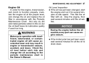
... Racing the engine before each ride and change the oil and replace the oil filter in the Owner's Manual. This fills the oil filter with insufficient, deteriorated, or contaminated engine oil will cause accelerated wear and may result in the oil, but the oil itself loses its lubricative quality if used , • If wait several minutes for the engine, transmission, and clutch to the periodic maintenance chart in...
... Racing the engine before each ride and change the oil and replace the oil filter in the Owner's Manual. This fills the oil filter with insufficient, deteriorated, or contaminated engine oil will cause accelerated wear and may result in the oil, but the oil itself loses its lubricative quality if used , • If wait several minutes for the engine, transmission, and clutch to the periodic maintenance chart in...

Owners Manual
Page 122
have the • If drive chain and/or the sprockets replaced by an authorized Kawasaki dealer. A. the rear wheel to inspect the • Rotate drive chain for damaged rollers, and NOTE żSprocket wear is an endless type and should not be cut for..., have it installed by an authorized Kawasaki dealer. It is exaggerated for installation; Also inspect the sprockets for wear limits. • loose pins and links. Good Teeth B. 120 MAINTENANCE AND ADJUSTMENT WARNING For safety, use only the standard chain. See Service Manual for unevenly or excessively worn teeth, and...
have the • If drive chain and/or the sprockets replaced by an authorized Kawasaki dealer. A. the rear wheel to inspect the • Rotate drive chain for damaged rollers, and NOTE żSprocket wear is an endless type and should not be cut for..., have it installed by an authorized Kawasaki dealer. It is exaggerated for installation; Also inspect the sprockets for wear limits. • loose pins and links. Good Teeth B. 120 MAINTENANCE AND ADJUSTMENT WARNING For safety, use only the standard chain. See Service Manual for unevenly or excessively worn teeth, and...

Owners Manual
Page 128
... brake light switch requires no adjustment, but the rear brake light switch should go on . 126 MAINTENANCE AND ADJUSTMENT WARNING Air in the brake lines diminish braking performance and can cause an accident resulting in accordance with the Periodic Maintenance Chart. If the brake lever or pedal feels mushy when it does not, ask your authorized Kawasaki dealer to "ON". Inspection Turn the ignition key to inspect the front brake light switch...
... brake light switch requires no adjustment, but the rear brake light switch should go on . 126 MAINTENANCE AND ADJUSTMENT WARNING Air in the brake lines diminish braking performance and can cause an accident resulting in accordance with the Periodic Maintenance Chart. If the brake lever or pedal feels mushy when it does not, ask your authorized Kawasaki dealer to "ON". Inspection Turn the ignition key to inspect the front brake light switch...

Owners Manual
Page 129
MAINTENANCE AND ADJUSTMENT 127 the operation of the rear brake • Check light switch by turning the switch body. • A. Brake Pedal B. Pedal Travel it does not, adjust the rear brake • If light switch. B. C. The brake light should go on after the proper pedal travel. Brake Pedal Travel 10 mm (0.4 in.) A. Adjustment To adjust the rear brake light switch, move the switch up or down by depressing the brake pedal. Rear Brake Light Switch Adjusting Nut Lights sooner Lights later • Connect the connector. D.
MAINTENANCE AND ADJUSTMENT 127 the operation of the rear brake • Check light switch by turning the switch body. • A. Brake Pedal B. Pedal Travel it does not, adjust the rear brake • If light switch. B. C. The brake light should go on after the proper pedal travel. Brake Pedal Travel 10 mm (0.4 in.) A. Adjustment To adjust the rear brake light switch, move the switch up or down by depressing the brake pedal. Rear Brake Light Switch Adjusting Nut Lights sooner Lights later • Connect the connector. D.

Owners Manual
Page 147
MAINTENANCE AND ADJUSTMENT 145 WARNING Substituting fuses can cause wiring to overheat, catch fire and/or fail. A. Main Fuse B. Failed Replace the blown fuse with a new one of the correct capacity, as specified on the junction box and main fuse. Normal B. Do not use any substitute for the standard fuse. Spare Fuse A.
MAINTENANCE AND ADJUSTMENT 145 WARNING Substituting fuses can cause wiring to overheat, catch fire and/or fail. A. Main Fuse B. Failed Replace the blown fuse with a new one of the correct capacity, as specified on the junction box and main fuse. Normal B. Do not use any substitute for the standard fuse. Spare Fuse A.

Owners Manual
Page 155
Brake Pedal Mounting Bolt 20. Front Brake Master Cylinder Clamp Bolt 16. Rear Shock Absorber Mounting Bolts 17. Rear Master Cylinder Mounting Bolts Front Axle Clamp Bolt 18. MAINTENANCE AND ADJUSTMENT 153 15. Front Axle Shaft 19.
Brake Pedal Mounting Bolt 20. Front Brake Master Cylinder Clamp Bolt 16. Rear Shock Absorber Mounting Bolts 17. Rear Master Cylinder Mounting Bolts Front Axle Clamp Bolt 18. MAINTENANCE AND ADJUSTMENT 153 15. Front Axle Shaft 19.
Owners Manual
Page 159
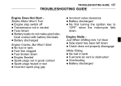
TROUBLESHOOTING GUIDE 157 TROUBLESHOOTING GUIDE Engine Does Not Start Starter Motor Won't Turn Engine stop switch off Transmission not in tank • No Fuel tank air vent is obstructed • Overheating • Battery discharged • Engine Stalls Just When Shifting Into 1st Gear Side stand has been left down Clutch does not properly disengage Engine Cranks, But Won't Start fuel in tank • No Fuel line clogged • Fuel broken down • Engine flooded • Spark plugs not in good contact •...
TROUBLESHOOTING GUIDE 157 TROUBLESHOOTING GUIDE Engine Does Not Start Starter Motor Won't Turn Engine stop switch off Transmission not in tank • No Fuel tank air vent is obstructed • Overheating • Battery discharged • Engine Stalls Just When Shifting Into 1st Gear Side stand has been left down Clutch does not properly disengage Engine Cranks, But Won't Start fuel in tank • No Fuel line clogged • Fuel broken down • Engine flooded • Spark plugs not in good contact •...