
Owners Manual
Page 7
... INFORMATION ...Meter Instruments ...Tachometer ...Instrument Display Brightness Control ...Multifunction Meter ...Warning/Indicator Lights ...Key ...Ignition Switch/Steering Lock ...Left Handlebar Switches ...Dimmer Switch ...Turn Signal Switch...Horn Button ...LAP/Passing Button...Power/S-KTRC Button...8 12 13 16 19 19 21 25 27 46 55 57 58 59 59 59 59 59 Right Handlebar Switches...Engine Stop Switch ...Starter Button ...START/STOP Switch (for Stop Watch) ...Brake Lever Adjuster...Fuel Tank Cap ...Fuel Tank ...Fuel Requirement ...Side Stand ...Seats ...Tool Kit ...Air Cleaner Intake ...Front...
... INFORMATION ...Meter Instruments ...Tachometer ...Instrument Display Brightness Control ...Multifunction Meter ...Warning/Indicator Lights ...Key ...Ignition Switch/Steering Lock ...Left Handlebar Switches ...Dimmer Switch ...Turn Signal Switch...Horn Button ...LAP/Passing Button...Power/S-KTRC Button...8 12 13 16 19 19 21 25 27 46 55 57 58 59 59 59 59 59 Right Handlebar Switches...Engine Stop Switch ...Starter Button ...START/STOP Switch (for Stop Watch) ...Brake Lever Adjuster...Fuel Tank Cap ...Fuel Tank ...Fuel Requirement ...Side Stand ...Seats ...Tool Kit ...Air Cleaner Intake ...Front...

Owners Manual
Page 8
... AND ADJUSTMENT Periodic Maintenance Chart...Engine Oil ...Cooling System ...Spark Plugs... 85 86 89 89 90 92 93 97 100 100 103 106 108 112 125 130 137 Evaporative Emission Control System (California model only)...Valve Clearance ...Kawasaki Clean Air System ...Exhaust Device ...Air Cleaner ...Throttle Control System ...Engine Vacuum Synchronization ...Idle Speed ...Clutch ...Drive Chain ...Brakes ...Brake Light Switches...Steering Damper ...Front Fork...Rear Shock Absorber...Wheels ...Battery...Headlight Beam...Fuses ...General Lubrication...Cleaning Your Motorcycle ...Bolt and Nut...
... AND ADJUSTMENT Periodic Maintenance Chart...Engine Oil ...Cooling System ...Spark Plugs... 85 86 89 89 90 92 93 97 100 100 103 106 108 112 125 130 137 Evaporative Emission Control System (California model only)...Valve Clearance ...Kawasaki Clean Air System ...Exhaust Device ...Air Cleaner ...Throttle Control System ...Engine Vacuum Synchronization ...Idle Speed ...Clutch ...Drive Chain ...Brakes ...Brake Light Switches...Steering Damper ...Front Fork...Rear Shock Absorber...Wheels ...Battery...Headlight Beam...Fuses ...General Lubrication...Cleaning Your Motorcycle ...Bolt and Nut...

Owners Manual
Page 15
Clutch Lever 2. Meter Instruments 6. 7. 8. 9. 10. 11. Left Handlebar Switches 3. Rebound Damping Force Adjuster (Front Fork) 4. Brake Fluid Reservoir (Front) Right Handlebar Switches Front Brake Lever Throttle Grip Ignition Switch/Steering Lock Steering Damper Compression damping force adjuster (Front Fork) 5. LOCATION OF PARTS 13 LOCATION OF PARTS 1.
Clutch Lever 2. Meter Instruments 6. 7. 8. 9. 10. 11. Left Handlebar Switches 3. Rebound Damping Force Adjuster (Front Fork) 4. Brake Fluid Reservoir (Front) Right Handlebar Switches Front Brake Lever Throttle Grip Ignition Switch/Steering Lock Steering Damper Compression damping force adjuster (Front Fork) 5. LOCATION OF PARTS 13 LOCATION OF PARTS 1.

Owners Manual
Page 17
Swingarm Rear Shock Absorber Brake Fluid Reservoir (Rear) Rear Brake Pedal Rear Brake Light Switch Oil Level Gauge LOCATION OF PARTS 15 32. 33. 34. 35. 36. 37. Fuse Boxes Battery Rebound damping force adjuster Fuel Tank Cap Coolant Reserve Tank Muffler 38. 39. 40. 41. 42. 43.
Swingarm Rear Shock Absorber Brake Fluid Reservoir (Rear) Rear Brake Pedal Rear Brake Light Switch Oil Level Gauge LOCATION OF PARTS 15 32. 33. 34. 35. 36. 37. Fuse Boxes Battery Rebound damping force adjuster Fuel Tank Cap Coolant Reserve Tank Muffler 38. 39. 40. 41. 42. 43.

Owners Manual
Page 20
... capability of adversely affecting stability and handling of the motorcycle's operation. 7. Weight attached to the aerodynamic force acting on motorcycle components caused by the use of such accessories will increase the mass of the steering assembly and can be remedied under warranty. Furthermore, any other vehicles. Kawasaki does not manufacture sidecars or trailers for the results of such unintended...
... capability of adversely affecting stability and handling of the motorcycle's operation. 7. Weight attached to the aerodynamic force acting on motorcycle components caused by the use of such accessories will increase the mass of the steering assembly and can be remedied under warranty. Furthermore, any other vehicles. Kawasaki does not manufacture sidecars or trailers for the results of such unintended...

Owners Manual
Page 33
NOTE żThe data is disconnected, the meter display resets to 0.0. żThe display unit modes can be changed, refer to select the trip meter A or B. "TRIP A" • To reset the trip meter: Push the upper button to the "Unit Setting" item in . GENERAL INFORMATION 31 • Push the lower button and hold it in this section. Trip Meter B. up power if the ignition switch is turned "OFF". żWhen the trip meter reaches 9999.9 while riding, the meter resets to 0.0 and continues counting. żWhen the battery is maintained by the back A.
NOTE żThe data is disconnected, the meter display resets to 0.0. żThe display unit modes can be changed, refer to select the trip meter A or B. "TRIP A" • To reset the trip meter: Push the upper button to the "Unit Setting" item in . GENERAL INFORMATION 31 • Push the lower button and hold it in this section. Trip Meter B. up power if the ignition switch is turned "OFF". żWhen the trip meter reaches 9999.9 while riding, the meter resets to 0.0 and continues counting. żWhen the battery is maintained by the back A.

Owners Manual
Page 35
... Gallon by back up power if the ignition switch is turned "OFF". żThe display unit modes can be changed, refer to the "Unit Setting" item in until the fuel consumption values resets to "- -. -". Fuel Consumption B. "L" the fuel consumption is dis• While played, push the lower button and hold it in this section. żWhen the battery is disconnected, the average mileage...
... Gallon by back up power if the ignition switch is turned "OFF". żThe display unit modes can be changed, refer to the "Unit Setting" item in until the fuel consumption values resets to "- -. -". Fuel Consumption B. "L" the fuel consumption is dis• While played, push the lower button and hold it in this section. żWhen the battery is disconnected, the average mileage...

Owners Manual
Page 36
... up start the stop watch starts timing laps. A. Stop Watch The stop watch. "START/STOP" Switch • • The stop watch can be used in this section. żWhen the battery is disconnected, the fuel consumption resets to "0.0". The stop watch is turned "OFF". żThe display unit modes can be changed, refer to the left. power if the ignition switch is...
... up start the stop watch starts timing laps. A. Stop Watch The stop watch. "START/STOP" Switch • • The stop watch can be used in this section. żWhen the battery is disconnected, the fuel consumption resets to "0.0". The stop watch is turned "OFF". żThe display unit modes can be changed, refer to the left. power if the ignition switch is...

Owners Manual
Page 40
... to the "Unit Setting" item in the unit depending on the unit mode setting, refer to coolant temperature meter by pushing the lower button. Coolant Temperature Meter The coolant temperature gauge indicates temperature of the engine coolant. NOTE żFor safety reasons, do not operate the instrument buttons while riding the motorcycle. żThe meter is selected. Warning Indicator Light (Red) C.
... to the "Unit Setting" item in the unit depending on the unit mode setting, refer to coolant temperature meter by pushing the lower button. Coolant Temperature Meter The coolant temperature gauge indicates temperature of the engine coolant. NOTE żFor safety reasons, do not operate the instrument buttons while riding the motorcycle. żThe meter is selected. Warning Indicator Light (Red) C.

Owners Manual
Page 46
... power while the ignition switch is turned "OFF". żWhen the battery is disconnected, the clock is reset to indicate favorable fuel consumption. Pushing and holding the button advances the hour or minute continuously. żThe clock works normally by step. Economical Riding Indicator The displays • Push stop blinking and the clock starts working again when the battery is driving...
... power while the ignition switch is turned "OFF". żWhen the battery is disconnected, the clock is reset to indicate favorable fuel consumption. Pushing and holding the button advances the hour or minute continuously. żThe clock works normally by step. Economical Riding Indicator The displays • Push stop blinking and the clock starts working again when the battery is driving...

Owners Manual
Page 64
Close the key hole cover. The key can be locked. Adjuster B. A. Mark NOTE żThe fuel tank cap cannot be closed without the key inserted, and the key cannot be removed unless the cap is locked properly. żDo not push on the key to close the cap, push it to the left to the right. 62 GENERAL INFORMATION Fuel Tank Cap To open the fuel tank cap, pull up the key hole cover. Insert the ignition key into place with the key inserted. To close the cap, or the cap cannot be removed by turning it down into the fuel tank cap and turn the key to the original position.
Close the key hole cover. The key can be locked. Adjuster B. A. Mark NOTE żThe fuel tank cap cannot be closed without the key inserted, and the key cannot be removed unless the cap is locked properly. żDo not push on the key to close the cap, push it to the left to the right. 62 GENERAL INFORMATION Fuel Tank Cap To open the fuel tank cap, pull up the key hole cover. Insert the ignition key into place with the key inserted. To close the cap, or the cap cannot be removed by turning it down into the fuel tank cap and turn the key to the original position.

Owners Manual
Page 106
... in .). Throttle ...Throttle grip play 2 ∼ 3 mm (0.08 ∼ 0.12 in .) left. 104 SAFE OPERATION Tires ...Air pressure (when cold): Front Rear 250 kPa (2.50 kgf/cm², 36 psi) 290 kPa (2.90 kgf/cm², 42 psi) Install the air valve cap. Drive chain ...Slack 25 ∼ 35 mm (1.0 ∼ 1.4 in .). Lubricate when chain is cold). Clutch lever operates smoothly. Electrical equipment ...All lights (Headlight, Tail/Brake Lights, Turn Signal Lights, Warning/Indicator Lights) and horn work.
... in .). Throttle ...Throttle grip play 2 ∼ 3 mm (0.08 ∼ 0.12 in .) left. 104 SAFE OPERATION Tires ...Air pressure (when cold): Front Rear 250 kPa (2.50 kgf/cm², 36 psi) 290 kPa (2.90 kgf/cm², 42 psi) Install the air valve cap. Drive chain ...Slack 25 ∼ 35 mm (1.0 ∼ 1.4 in .). Lubricate when chain is cold). Clutch lever operates smoothly. Electrical equipment ...All lights (Headlight, Tail/Brake Lights, Turn Signal Lights, Warning/Indicator Lights) and horn work.

Owners Manual
Page 108
... properly. Engine Oil: To avoid engine seizure and resulting loss of control, make sure that the handlebar turns freely but has no play. Steering: Looseness in good condition. Fuel: Have sufficient fuel for High Speed Operation Brakes: The importance of control. Tires: High speed operation is at the upper level line. Electrical Equipment: Make sure that all safety related parts are tight and that the headlight, tail/brake light, turn signals, horn, etc...
... properly. Engine Oil: To avoid engine seizure and resulting loss of control, make sure that the handlebar turns freely but has no play. Steering: Looseness in good condition. Fuel: Have sufficient fuel for High Speed Operation Brakes: The importance of control. Tires: High speed operation is at the upper level line. Electrical Equipment: Make sure that all safety related parts are tight and that the headlight, tail/brake light, turn signals, horn, etc...

Owners Manual
Page 121
...; • • • • • • • • 165 166 169/ 176 year • 169/ 176 inspect Brake light switch operation - inspect Suspensions: Front forks/rear shock absorber operation (damping and smooth stroke) inspect Front forks/rear shock absorber oil leak - MAINTENANCE AND ADJUSTMENT 119 Frequency Whichever comes first *Odometer Reading km × 1000 (mile × 1000) See Page Operation (Chassis Items...
...; • • • • • • • • 165 166 169/ 176 year • 169/ 176 inspect Brake light switch operation - inspect Suspensions: Front forks/rear shock absorber operation (damping and smooth stroke) inspect Front forks/rear shock absorber oil leak - MAINTENANCE AND ADJUSTMENT 119 Frequency Whichever comes first *Odometer Reading km × 1000 (mile × 1000) See Page Operation (Chassis Items...
Owners Manual
Page 127
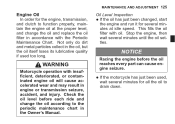
... wear and may result in the Owner's Manual. Oil Level Inspection If the oil has just been changed, start the engine and run it for all the oil to drain down. Check the oil level before the oil reaches every part can cause engine seizure. WARNING Motorcycle operation with oil. MAINTENANCE AND ADJUSTMENT 125 Engine Oil In order for the engine, transmission, and clutch to function properly, maintain the engine oil at idle speed.
... wear and may result in the Owner's Manual. Oil Level Inspection If the oil has just been changed, start the engine and run it for all the oil to drain down. Check the oil level before the oil reaches every part can cause engine seizure. WARNING Motorcycle operation with oil. MAINTENANCE AND ADJUSTMENT 125 Engine Oil In order for the engine, transmission, and clutch to function properly, maintain the engine oil at idle speed.

Owners Manual
Page 162
...Footpeg Bracket Bolt: 25 N·m (2.5 kgf·m, 18 ft·lb) NOTE żSprocket wear is an endless type and should not be cut for il- WARNING For safety, use only the standard chain. have it installed by an authorized Kawasaki dealer. See Service Manual for un&#...both footpegs are same position. żApply the nonpermanent locking agent to inspect the • Rotate drive chain for damaged rollers, and inspect the sprockets for wear limits. 160 MAINTENANCE AND ADJUSTMENT NOTE żInstall the chain cover and front foot- the rear wheel to the chain cover font side bolt.
...Footpeg Bracket Bolt: 25 N·m (2.5 kgf·m, 18 ft·lb) NOTE żSprocket wear is an endless type and should not be cut for il- WARNING For safety, use only the standard chain. have it installed by an authorized Kawasaki dealer. See Service Manual for un&#...both footpegs are same position. żApply the nonpermanent locking agent to inspect the • Rotate drive chain for damaged rollers, and inspect the sprockets for wear limits. 160 MAINTENANCE AND ADJUSTMENT NOTE żInstall the chain cover and front foot- the rear wheel to the chain cover font side bolt.

Owners Manual
Page 168
... MAINTENANCE AND ADJUSTMENT Brake Light Switches When either the front or rear brake is applied. Brake Pedal Travel 10 mm (0.4 in .) C. Brake Pedal B. 10 mm (0.4 in .) The front brake light switch requires no adjustment, but the rear brake light switch should go on . Bolts it does not, ask an authorized Kawasaki dealer to "ON". the operation of the rear brake • Check light switch by depressing the brake pedal. Inspection Turn the ignition key to...
... MAINTENANCE AND ADJUSTMENT Brake Light Switches When either the front or rear brake is applied. Brake Pedal Travel 10 mm (0.4 in .) C. Brake Pedal B. 10 mm (0.4 in .) The front brake light switch requires no adjustment, but the rear brake light switch should go on . Bolts it does not, ask an authorized Kawasaki dealer to "ON". the operation of the rear brake • Check light switch by depressing the brake pedal. Inspection Turn the ignition key to...

Owners Manual
Page 169
Rear Brake Light Switch B. To adjust the rear brake light switch, move the switch up or down by turning the adjusting nut. • • • A. MAINTENANCE AND ADJUSTMENT 167 Adjustment Remove the right front footpeg bracket bolts. Adjusting Nut C. Lights later E. Pull the front footpeg bracket a little bit outward. Lights sooner D. Viewed from behind the bracket NOTICE To avoid damaging the electrical connections inside the switch, be sure that the switch body does not turn during adjustment.
Rear Brake Light Switch B. To adjust the rear brake light switch, move the switch up or down by turning the adjusting nut. • • • A. MAINTENANCE AND ADJUSTMENT 167 Adjustment Remove the right front footpeg bracket bolts. Adjusting Nut C. Lights later E. Pull the front footpeg bracket a little bit outward. Lights sooner D. Viewed from behind the bracket NOTICE To avoid damaging the electrical connections inside the switch, be sure that the switch body does not turn during adjustment.

Owners Manual
Page 209
Front Fender Mounting Bolts 7. Front Axle Clamp Bolts 11. Swingarm Pivot Shaft Nut 16. MAINTENANCE AND ADJUSTMENT 207 6. Brake Disc Mounting Bolts 10. Footpeg Mounting Bolts 17. Suspension Likage Tie-Rod Nuts 15. Rear Shock Absorber Mounting Bolts 18. Rear Sprocket Nuts Side Stand Bolt 14. Caliper Mounting Bolts 13. Rear Axle Nut 19. Rear Frame Mounting Bolts 9. Engine Mounting Bolts and Nuts 8. Front Axle Nut 12.
Front Fender Mounting Bolts 7. Front Axle Clamp Bolts 11. Swingarm Pivot Shaft Nut 16. MAINTENANCE AND ADJUSTMENT 207 6. Brake Disc Mounting Bolts 10. Footpeg Mounting Bolts 17. Suspension Likage Tie-Rod Nuts 15. Rear Shock Absorber Mounting Bolts 18. Rear Sprocket Nuts Side Stand Bolt 14. Caliper Mounting Bolts 13. Rear Axle Nut 19. Rear Frame Mounting Bolts 9. Engine Mounting Bolts and Nuts 8. Front Axle Nut 12.

Owners Manual
Page 229
LOCATION OF LABELS 227 9. *10. *11. 12. Vehicle Emission Control Information Vacuum Hose Routing Diagram Fuel level Fuel Notice * : only on California model
LOCATION OF LABELS 227 9. *10. *11. 12. Vehicle Emission Control Information Vacuum Hose Routing Diagram Fuel level Fuel Notice * : only on California model