
Owners Manual
Page 8
... Instruments ...Speedometer: ...Digital Display ...Fuel Gauge: ...RESET Button/MODE Button: ...Warning/Indicator Lights: ...Keys ...Ignition Switch ...Right Handlebar Switches...Engine Stop Switch: ...Starter Button: ...Left Handlebar Switches ...Dimmer Switch: ...Turn Signal Switch:...9 13 14 17 21 24 24 25 25 28 28 28 30 31 33 33 33 34 34 34 Horn Button: ...Brake Lever Adjusters...Fuel Tank Cap ...Fuel Tank ...Side Stand ...Seat...Tool Kit Case ...Helmet-Hook ...Windshield...Special Warning on the Use of Saddlebags...Saddlebags ...Steering Lock ...Electric Accessory...
... Instruments ...Speedometer: ...Digital Display ...Fuel Gauge: ...RESET Button/MODE Button: ...Warning/Indicator Lights: ...Keys ...Ignition Switch ...Right Handlebar Switches...Engine Stop Switch: ...Starter Button: ...Left Handlebar Switches ...Dimmer Switch: ...Turn Signal Switch:...9 13 14 17 21 24 24 25 25 28 28 28 30 31 33 33 33 34 34 34 Horn Button: ...Brake Lever Adjusters...Fuel Tank Cap ...Fuel Tank ...Side Stand ...Seat...Tool Kit Case ...Helmet-Hook ...Windshield...Special Warning on the Use of Saddlebags...Saddlebags ...Steering Lock ...Electric Accessory...

Owners Manual
Page 9
... Periodic Maintenance Chart...Engine Oil ...Cooling System ...Drive Belt...Spark Plugs...Evaporative Emission Control System (California model only) ...Valve Clearance ...Kawasaki Clean Air System ... 65 68 69 70 71 73 75 75 78 81 83 88 100 107 113 114 115 116 117 Air Cleaner ...Throttle Control System ...Idle Speed ...Clutch ...Brakes ...Brake Light Switches...Rear Shock Absorber...Wheels ...Battery...Headlight Beam...Fuses ...General Lubrication...Cleaning Your Motorcycle ...Bolt and Nut Tightening...STORAGE ...TROUBLESHOOTING GUIDE...YOUR WARRANTY/OWNER SATISFACTION ...Reporting Safety...
... Periodic Maintenance Chart...Engine Oil ...Cooling System ...Drive Belt...Spark Plugs...Evaporative Emission Control System (California model only) ...Valve Clearance ...Kawasaki Clean Air System ... 65 68 69 70 71 73 75 75 78 81 83 88 100 107 113 114 115 116 117 Air Cleaner ...Throttle Control System ...Idle Speed ...Clutch ...Brakes ...Brake Light Switches...Rear Shock Absorber...Wheels ...Battery...Headlight Beam...Fuses ...General Lubrication...Cleaning Your Motorcycle ...Bolt and Nut Tightening...STORAGE ...TROUBLESHOOTING GUIDE...YOUR WARRANTY/OWNER SATISFACTION ...Reporting Safety...

Owners Manual
Page 10
SPECIFICATIONS 9 SPECIFICATIONS PERFORMANCE Minimum Turning Radius DIMENSIONS Overall Length Overall Width Overall Height Wheelbase Road Clearance Curb Mass ENGINE Type Displacement Bore × Stroke Compression Ratio Starting System SOHC, V-type 2-cylinder, 4-stroke, liquid-cooled 903 cm³ (55.1 cu in.) 88.0 × 74.2 mm (3.5 × 2.9 in.) 9.5 : 1 Electric starter 2 465 mm (97.0 in.) 1 005 mm (39.6 in.) 1 480 mm (58.3 in.) 1 645 mm (64.8 in.) 135 mm (5.31 in.) 298 kg (657 lb) 2.9 m (114 in.)
SPECIFICATIONS 9 SPECIFICATIONS PERFORMANCE Minimum Turning Radius DIMENSIONS Overall Length Overall Width Overall Height Wheelbase Road Clearance Curb Mass ENGINE Type Displacement Bore × Stroke Compression Ratio Starting System SOHC, V-type 2-cylinder, 4-stroke, liquid-cooled 903 cm³ (55.1 cu in.) 88.0 × 74.2 mm (3.5 × 2.9 in.) 9.5 : 1 Electric starter 2 465 mm (97.0 in.) 1 005 mm (39.6 in.) 1 480 mm (58.3 in.) 1 645 mm (64.8 in.) 135 mm (5.31 in.) 298 kg (657 lb) 2.9 m (114 in.)

Owners Manual
Page 16
Brake Disc Brake Caliper Wheel Radiator Shift Pedal Oil Level Inspection Window 26. LOCATION OF PARTS 15 12. 13. 14. 15. 16. 17. 18. 19. Side Stand Fuse Box Coolant Reserve Tank Rear Shock Absorber Belt Belt Pulley Front Fork Headlight Turn Signal Light Horn Windshield Spark Plugs Battery Saddlebag 20. 21. 22. 23. 24. 25. Side Stand Switch 27. 28. 29. 30. 31. 32.
Brake Disc Brake Caliper Wheel Radiator Shift Pedal Oil Level Inspection Window 26. LOCATION OF PARTS 15 12. 13. 14. 15. 16. 17. 18. 19. Side Stand Fuse Box Coolant Reserve Tank Rear Shock Absorber Belt Belt Pulley Front Fork Headlight Turn Signal Light Horn Windshield Spark Plugs Battery Saddlebag 20. 21. 22. 23. 24. 25. Side Stand Switch 27. 28. 29. 30. 31. 32.

Owners Manual
Page 17
Idle Speed Adjusting Screw 41. Brake Fluid Reservoir (Rear) Mufflers 40. Rear Brake Pedal 42. 16 LOCATION OF PARTS 33. 34. 35. 36. 37. Tail/Brake Light Seat Tool Kit Case/Tool Kit Air Cleaner Element Fuel Tank 38. Rear Brake Light Switch 43. Steering Lock 39.
Idle Speed Adjusting Screw 41. Brake Fluid Reservoir (Rear) Mufflers 40. Rear Brake Pedal 42. 16 LOCATION OF PARTS 33. 34. 35. 36. 37. Tail/Brake Light Seat Tool Kit Case/Tool Kit Air Cleaner Element Fuel Tank 38. Rear Brake Light Switch 43. Steering Lock 39.

Owners Manual
Page 24
... acting on handling or stability, but can only warn that the effects can be remedied under warranty. Kawasaki does not manufacture sidecars or trailers for the results of such unintended use of such accessories will increase the mass of the steering assembly and can result in an unsafe riding condition. 8. Maximum Load Weight of the motorcycle. Weight attached to tow any trailer or...
... acting on handling or stability, but can only warn that the effects can be remedied under warranty. Kawasaki does not manufacture sidecars or trailers for the results of such unintended use of such accessories will increase the mass of the steering assembly and can result in an unsafe riding condition. 8. Maximum Load Weight of the motorcycle. Weight attached to tow any trailer or...

Owners Manual
Page 27
... the back-up power while the ignition switch is turned off. ○When the battery is connected. NOTE the RESET button. tarily advances the hour or minute step by step. Push the MODE button to 1:00, and starts working . 26 GENERAL INFORMATION display starts flashing. The displays stop flashing and the clock starts working again when the battery is disconnected, the...
... the back-up power while the ignition switch is turned off. ○When the battery is connected. NOTE the RESET button. tarily advances the hour or minute step by step. Push the MODE button to 1:00, and starts working . 26 GENERAL INFORMATION display starts flashing. The displays stop flashing and the clock starts working again when the battery is disconnected, the...

Owners Manual
Page 29
Warning/Indicator Lights: N: When the transmission is in neutral, the neutral indicator light is lit. : When the headlight is on high beam, the high beam indicator light is used to reset the trip meter and to adjust the clock. When the needle comes near ...power if the ignition key is turned to "OFF". ○When the trip meter reaches 999.9 while riding, the meter resets to 0.0 and continue counting. ○When the battery is used to shift through the digital display modes and to 0.0. When vehicle stands with side stand, fuel gauge cannot show the amount of fuel in the fuel tank...
Warning/Indicator Lights: N: When the transmission is in neutral, the neutral indicator light is lit. : When the headlight is on high beam, the high beam indicator light is used to reset the trip meter and to adjust the clock. When the needle comes near ...power if the ignition key is turned to "OFF". ○When the trip meter reaches 999.9 while riding, the meter resets to 0.0 and continue counting. ○When the battery is used to shift through the digital display modes and to 0.0. When vehicle stands with side stand, fuel gauge cannot show the amount of fuel in the fuel tank...

Owners Manual
Page 33
... and P (Park) licence plate light on . All other electrical circuits cut off . To avoid battery discharge, always start the engine immediately after starting the engine. All electrical circuits off . 32 GENERAL INFORMATION OFF ON Engine off . ○Tail and, license plate lights are on when the starter button is in the ON position The headlight goes on NOTE whenever the ignition switch is released after turning the ignition key to...
... and P (Park) licence plate light on . All other electrical circuits cut off . To avoid battery discharge, always start the engine immediately after starting the engine. All electrical circuits off . 32 GENERAL INFORMATION OFF ON Engine off . ○Tail and, license plate lights are on when the starter button is in the ON position The headlight goes on NOTE whenever the ignition switch is released after turning the ignition key to...

Owners Manual
Page 37
... the key hole cover. Ignition Key B. Key Hole Cover The key can be locked. Fuel Tank Cap ○The fuel tank cap cannot be closed NOTE without the key inserted, and the key cannot be removed unless the cap is locked properly. ○Do not push on the key to close the cap, push it to the left to the right. A. Fuel Tank Cap C. To close the cap or the cap cannot be removed by turning...
... the key hole cover. Ignition Key B. Key Hole Cover The key can be locked. Fuel Tank Cap ○The fuel tank cap cannot be closed NOTE without the key inserted, and the key cannot be removed unless the cap is locked properly. ○Do not push on the key to close the cap, push it to the left to the right. A. Fuel Tank Cap C. To close the cap or the cap cannot be removed by turning...

Owners Manual
Page 67
When the motorcycle is equipped with a NOTE positive neutral finder. The transmission will shift only into neutral. 66 HOW TO RIDE THE MOTORCYCLE the throttle part way, while re• Open leasing the clutch lever. ○The transmission is standing still, the transmission cannot be shifted past neutral from 1st gear. To use the positive neutral finder, shift down to 1st gear, then lift up on the shift pedal while standing still.
When the motorcycle is equipped with a NOTE positive neutral finder. The transmission will shift only into neutral. 66 HOW TO RIDE THE MOTORCYCLE the throttle part way, while re• Open leasing the clutch lever. ○The transmission is standing still, the transmission cannot be shifted past neutral from 1st gear. To use the positive neutral finder, shift down to 1st gear, then lift up on the shift pedal while standing still.

Owners Manual
Page 80
...psi) Install the air valve cap. Clutch ...Clutch lever play 2 ∼ 3 mm (0.08 ∼ 0.12 in .). Throttle ...Throttle grip play 2 ∼ 3 mm (0.08 ∼ 0.12 in .). No brake fluid leakage. Engine stop switch ...Stops engine. Brakes ...Brake pad wear: Lining thickness more than 1 mm (0.04 in.) left. Electrical equipment ...All lights (Headlight, Tail/Brake Lights, Turn Signal Lights Warning/Indicator Lights) and horn work. No binding of control cables. Coolant ...No coolant leakage. Coolant level between level lines (when engine is cold). Clutch lever operates...
...psi) Install the air valve cap. Clutch ...Clutch lever play 2 ∼ 3 mm (0.08 ∼ 0.12 in .). Throttle ...Throttle grip play 2 ∼ 3 mm (0.08 ∼ 0.12 in .). No brake fluid leakage. Engine stop switch ...Stops engine. Brakes ...Brake pad wear: Lining thickness more than 1 mm (0.04 in.) left. Electrical equipment ...All lights (Headlight, Tail/Brake Lights, Turn Signal Lights Warning/Indicator Lights) and horn work. No binding of control cables. Coolant ...No coolant leakage. Coolant level between level lines (when engine is cold). Clutch lever operates...

Owners Manual
Page 95
inspect Brake light switch operation - inspect year 6 months year *Odometer Reading km × 1 000 (mile × 1 000) See Page Every 1 6 12 18 24 30 36 (0.6) (3.75) (7.5) (11.25) (15) (18.75) (22.5) 125 126 126 129 129 inspect Brake fluid level inspect Brake operation (effectiveness, play, drag) - 94 MAINTENANCE AND ADJUSTMENT Frequency Whichever comes first Operation (Chassis Items) Brake pad wear inspect # K Brake hose installation condition -
inspect Brake light switch operation - inspect year 6 months year *Odometer Reading km × 1 000 (mile × 1 000) See Page Every 1 6 12 18 24 30 36 (0.6) (3.75) (7.5) (11.25) (15) (18.75) (22.5) 125 126 126 129 129 inspect Brake fluid level inspect Brake operation (effectiveness, play, drag) - 94 MAINTENANCE AND ADJUSTMENT Frequency Whichever comes first Operation (Chassis Items) Brake pad wear inspect # K Brake hose installation condition -
Owners Manual
Page 101
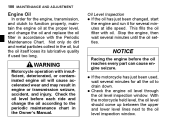
... ride and change the oil and replace the oil filter in engine or transmission seizure, accident, and injury. 100 MAINTENANCE AND ADJUSTMENT In order for the engine, transmission, and clutch to function properly, maintain the engine oil at idle speed. Engine Oil Oil Level Inspection If the oil has just been changed, start the engine and run it for several minutes at the proper level, and change the oil according to the oil level inspection window. Not...
... ride and change the oil and replace the oil filter in engine or transmission seizure, accident, and injury. 100 MAINTENANCE AND ADJUSTMENT In order for the engine, transmission, and clutch to function properly, maintain the engine oil at idle speed. Engine Oil Oil Level Inspection If the oil has just been changed, start the engine and run it for several minutes at the proper level, and change the oil according to the oil level inspection window. Not...

Owners Manual
Page 103
Contact your local authorities for approved disposal methods or possible recycling. • Remove the cover. A. Engine Oil Drain Plug the oil completely drain with • Let the motorcycle perpendicular to the ground. A. Cover B. Place an oil pan beneath the engine. Remove the engine oil drain plug. • • • WARNING Engine oil is a toxic substance. 102 MAINTENANCE AND ADJUSTMENT Oil and/or Oil Filter Change Warm up the engine thoroughly, and then stop it. Dispose of used oil properly. Bolt
Contact your local authorities for approved disposal methods or possible recycling. • Remove the cover. A. Engine Oil Drain Plug the oil completely drain with • Let the motorcycle perpendicular to the ground. A. Cover B. Place an oil pan beneath the engine. Remove the engine oil drain plug. • • • WARNING Engine oil is a toxic substance. 102 MAINTENANCE AND ADJUSTMENT Oil and/or Oil Filter Change Warm up the engine thoroughly, and then stop it. Dispose of used oil properly. Bolt

Owners Manual
Page 130
... the front and rear brakes. MAINTENANCE AND ADJUSTMENT 129 Fluid Change Have the brake fluid changed by an authorized Kawasaki dealer. • • • If it is automatically compensated for and has no effect on . The brake light should be defective. Front and Rear Brakes Disc and disc pad wear is applied, there might be air in injury or death. Brake Light Switches WARNING Air in the brake lines diminish braking performance and can...
... the front and rear brakes. MAINTENANCE AND ADJUSTMENT 129 Fluid Change Have the brake fluid changed by an authorized Kawasaki dealer. • • • If it is automatically compensated for and has no effect on . The brake light should be defective. Front and Rear Brakes Disc and disc pad wear is applied, there might be air in injury or death. Brake Light Switches WARNING Air in the brake lines diminish braking performance and can...

Owners Manual
Page 131
130 MAINTENANCE AND ADJUSTMENT the operation of pedal travel. A. NOTICE To avoid damaging the electrical connections inside the switch, be sure that the switch body does not turn during adjustment. it does not, adjust the rear brake • If light switch. • Adjustment To adjust the rear brake light switch, move the switch up or down by depressing the brake pedal. Brake Pedal B. 10 mm (0.4 in .) of the rear brake • Check light switch by turning the adjusting nut. The brake light should go on after about 10 mm (0.4 in .)
130 MAINTENANCE AND ADJUSTMENT the operation of pedal travel. A. NOTICE To avoid damaging the electrical connections inside the switch, be sure that the switch body does not turn during adjustment. it does not, adjust the rear brake • If light switch. • Adjustment To adjust the rear brake light switch, move the switch up or down by depressing the brake pedal. Brake Pedal B. 10 mm (0.4 in .) of the rear brake • Check light switch by turning the adjusting nut. The brake light should go on after about 10 mm (0.4 in .)

Owners Manual
Page 132
Rear Shock Absorber A. Rear Brake Light Switch Adjusting Nut Lights sooner. C. D. Lights later. B. MAINTENANCE AND ADJUSTMENT 131 The rear shock absorber can be adjusted by changing the spring preload for various riding and loading conditions.
Rear Shock Absorber A. Rear Brake Light Switch Adjusting Nut Lights sooner. C. D. Lights later. B. MAINTENANCE AND ADJUSTMENT 131 The rear shock absorber can be adjusted by changing the spring preload for various riding and loading conditions.

Owners Manual
Page 150
A. Failed MAINTENANCE AND ADJUSTMENT 149 WARNING Substituting fuses can cause wiring to overheat, catch fire and/or fail. Do not use any substitute for the standard fuse. Replace the blown fuse with a new one of the correct capacity, as specified on the junction box and main fuse. Normal B.
A. Failed MAINTENANCE AND ADJUSTMENT 149 WARNING Substituting fuses can cause wiring to overheat, catch fire and/or fail. Do not use any substitute for the standard fuse. Replace the blown fuse with a new one of the correct capacity, as specified on the junction box and main fuse. Normal B.

Owners Manual
Page 153
... stop the engine. Avoid wire brushes, steel wool, and all harsh chemicals, solvents, • Avoid detergents, and household cleaning products such as they can easily be scratched. When operating the vehicle in an enclosed space prior to seals, • Avoid brake pads, and tires. sure the engine and exhaust are • Be cool before washing. 152 MAINTENANCE AND ADJUSTMENT WARNING Build...
... stop the engine. Avoid wire brushes, steel wool, and all harsh chemicals, solvents, • Avoid detergents, and household cleaning products such as they can easily be scratched. When operating the vehicle in an enclosed space prior to seals, • Avoid brake pads, and tires. sure the engine and exhaust are • Be cool before washing. 152 MAINTENANCE AND ADJUSTMENT WARNING Build...