

Owners Manual
Page 8
... ...GENERAL INFORMATION ...Meter Instruments ...Speedometer: ...Digital Display ...Fuel Gauge: ...RESET Button/MODE button: ...Warning/Indicator Lights: ...Keys ...Ignition Switch ...Right Handlebar Switches...Engine Stop Switch: ...Starter Button: ...Left Handlebar Switches ...Dimmer Switch: ...Turn Signal Switch:...9 13 14 17 21 24 24 25 25 28 28 28 30 31 33 33 33 34 34 34 Horn Button: ...Brake Lever Adjusters...Fuel Tank Cap ...Fuel Tank ...Side Stand ...Seat...Tool Kit Case ...Helmet-Hook ...Steering Lock ...Electric Accessory Connectors ...Rear View Mirror ...BREAK-IN...
... ...GENERAL INFORMATION ...Meter Instruments ...Speedometer: ...Digital Display ...Fuel Gauge: ...RESET Button/MODE button: ...Warning/Indicator Lights: ...Keys ...Ignition Switch ...Right Handlebar Switches...Engine Stop Switch: ...Starter Button: ...Left Handlebar Switches ...Dimmer Switch: ...Turn Signal Switch:...9 13 14 17 21 24 24 25 25 28 28 28 30 31 33 33 33 34 34 34 Horn Button: ...Brake Lever Adjusters...Fuel Tank Cap ...Fuel Tank ...Side Stand ...Seat...Tool Kit Case ...Helmet-Hook ...Steering Lock ...Electric Accessory Connectors ...Rear View Mirror ...BREAK-IN...
Owners Manual
Page 9
...Periodic Maintenance Chart...Engine Oil ...Cooling System ...Drive Belt...Spark Plugs...Evaporative Emission Control System (California model only) ...Valve Clearance ...Kawasaki Clean Air System ...Air Cleaner ...Throttle Control System ... 65 66 68 70 70 73 75 77 82 92 99 105 106 107 108 109 110 112 Idle Speed ...Clutch ...Brakes ...Brake Light Switches...Rear Shock Absorber...Wheels ...Battery...Headlight Beam...Fuses ...General Lubrication...Cleaning Your Motorcycle ...Bolt and Nut Tightening...STORAGE ...TROUBLESHOOTING GUIDE...YOUR WARRANTY/OWNER SATISFACTION ...Reporting Safety Defects...
...Periodic Maintenance Chart...Engine Oil ...Cooling System ...Drive Belt...Spark Plugs...Evaporative Emission Control System (California model only) ...Valve Clearance ...Kawasaki Clean Air System ...Air Cleaner ...Throttle Control System ... 65 66 68 70 70 73 75 77 82 92 99 105 106 107 108 109 110 112 Idle Speed ...Clutch ...Brakes ...Brake Light Switches...Rear Shock Absorber...Wheels ...Battery...Headlight Beam...Fuses ...General Lubrication...Cleaning Your Motorcycle ...Bolt and Nut Tightening...STORAGE ...TROUBLESHOOTING GUIDE...YOUR WARRANTY/OWNER SATISFACTION ...Reporting Safety Defects...
Owners Manual
Page 16
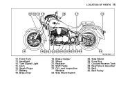
Front Fork Headlight Turn Signal Light Horn Spark Plugs Battery Brake Disc 19. 20. 21. 22. 23. Side Stand Switch 25. 26. 27. 28. 29. 30. Brake Caliper Wheel Radiator Shift Pedal Oil Level Inspection Window 24. Side Stand Fuse Box Coolant Reserve Tank Rear Shock Absorber Belt Belt Pulley LOCATION OF PARTS 15 12. 13. 14. 15. 16. 17. 18.
Front Fork Headlight Turn Signal Light Horn Spark Plugs Battery Brake Disc 19. 20. 21. 22. 23. Side Stand Switch 25. 26. 27. 28. 29. 30. Brake Caliper Wheel Radiator Shift Pedal Oil Level Inspection Window 24. Side Stand Fuse Box Coolant Reserve Tank Rear Shock Absorber Belt Belt Pulley LOCATION OF PARTS 15 12. 13. 14. 15. 16. 17. 18.
Owners Manual
Page 17
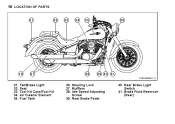
Mufflers 38. Rear Brake Light Switch 41. Brake Fluid Reservoir (Rear) 16 LOCATION OF PARTS 31. 32. 33. 34. 35. Rear Brake Pedal 40. Steering Lock 37. Tail/Brake Light Seat Tool Kit Case/Tool Kit Air Cleaner Element Fuel Tank 36. Idle Speed Adjusting Screw 39.
Mufflers 38. Rear Brake Light Switch 41. Brake Fluid Reservoir (Rear) 16 LOCATION OF PARTS 31. 32. 33. 34. 35. Rear Brake Pedal 40. Steering Lock 37. Tail/Brake Light Seat Tool Kit Case/Tool Kit Air Cleaner Element Fuel Tank 36. Idle Speed Adjusting Screw 39.
Owners Manual
Page 24
... of their weight, but can only warn that Kawasaki cannot assume responsibility for motorcycles and cannot predict the effects of such accessories on handling or stability, but also due to be remedied under warranty. Poorly designed or installed items can be adverse and that the effects can result in an unsafe riding condition. 9. Maximum Load Weight of the...
... of their weight, but can only warn that Kawasaki cannot assume responsibility for motorcycles and cannot predict the effects of such accessories on handling or stability, but also due to be remedied under warranty. Poorly designed or installed items can be adverse and that the effects can result in an unsafe riding condition. 9. Maximum Load Weight of the...
Owners Manual
Page 27
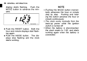
... the RESET button. The displays stop flashing and the clock starts working again when the battery is connected. Pushing and holding the button advance the hour or minute continuously. ○The clock works normally from the back-up power while the ignition switch is turned off. ○When the battery is disconnected, the clock resets to advance the minutes...
... the RESET button. The displays stop flashing and the clock starts working again when the battery is connected. Pushing and holding the button advance the hour or minute continuously. ○The clock works normally from the back-up power while the ignition switch is turned off. ○When the battery is disconnected, the clock resets to advance the minutes...
Owners Manual
Page 29
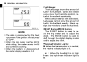
...;When the battery is used to shift through the digital display modes and to adjust the clock. The MODE button is used to reset the trip meter and to 0.0. Warning/Indicator Lights: N: When the transmission is in the fuel tank exactly. 28 GENERAL INFORMATION Fuel Gauge: The fuel gauge shows the amount of fuel in neutral, the neutral indicator light is lit. : When the headlight is...
...;When the battery is used to shift through the digital display modes and to adjust the clock. The MODE button is used to reset the trip meter and to 0.0. Warning/Indicator Lights: N: When the transmission is in the fuel tank exactly. 28 GENERAL INFORMATION Fuel Gauge: The fuel gauge shows the amount of fuel in neutral, the neutral indicator light is lit. : When the headlight is...
Owners Manual
Page 33
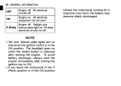
... electrical equipment can be used. The headlight goes on . Engine on NOTE whenever the ignition switch is released after turning the ignition key to ON. ○If you leave the motorcycle in the P (Park) position or in the ON position. without the motorcycle running for a long time (one hour), the battery may become totally discharged. To avoid battery discharge, always start the engine immediately after starting the engine...
... electrical equipment can be used. The headlight goes on . Engine on NOTE whenever the ignition switch is released after turning the ignition key to ON. ○If you leave the motorcycle in the P (Park) position or in the ON position. without the motorcycle running for a long time (one hour), the battery may become totally discharged. To avoid battery discharge, always start the engine immediately after starting the engine...
Owners Manual
Page 37
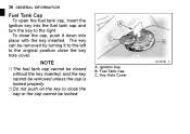
... be removed by turning it down into the fuel tank cap and turn the key to close the key hole cover. Ignition Key B. Key Hole Cover A. Fuel Tank Cap C. Fuel Tank Cap ○The fuel tank cap cannot be closed NOTE without the key inserted, and the key cannot be locked. 36 GENERAL INFORMATION To open the fuel tank cap, insert the ignition key into place with the key inserted. To close the cap, push it to the left to the...
... be removed by turning it down into the fuel tank cap and turn the key to close the key hole cover. Ignition Key B. Key Hole Cover A. Fuel Tank Cap C. Fuel Tank Cap ○The fuel tank cap cannot be closed NOTE without the key inserted, and the key cannot be locked. 36 GENERAL INFORMATION To open the fuel tank cap, insert the ignition key into place with the key inserted. To close the cap, push it to the left to the...
Owners Manual
Page 62
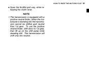
To use the positive neutral finder, shift down to 1st gear, then lift up on the shift pedal while standing still. When the motorcycle is equipped with a NOTE positive neutral finder. The transmission will shift only into neutral. HOW TO RIDE THE MOTORCYCLE 61 the throttle part way, while re• Open leasing the clutch lever. ○The transmission is standing still, the transmission cannot be shifted past neutral from 1st gear.
To use the positive neutral finder, shift down to 1st gear, then lift up on the shift pedal while standing still. When the motorcycle is equipped with a NOTE positive neutral finder. The transmission will shift only into neutral. HOW TO RIDE THE MOTORCYCLE 61 the throttle part way, while re• Open leasing the clutch lever. ○The transmission is standing still, the transmission cannot be shifted past neutral from 1st gear.
Owners Manual
Page 75
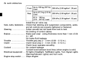
... between level lines (when engine is cold). Brakes ...Brake pad wear: Lining thickness more than 1 mm (0.04 in .). 74 SAFE OPERATION Front Rear Up to 180 kg (397 lb) 200 kPa (2.00 kgf/cm², 28 psi) Load Up to lock. Coolant ...No coolant leakage. No binding of control cables. No brake fluid leakage. Electrical equipment ...All lights (Headlight, Tail/Brake Lights, Turn Signal Lights Warning/Indicator Lights) and horn work. Steering ...Action smooth but not...
... between level lines (when engine is cold). Brakes ...Brake pad wear: Lining thickness more than 1 mm (0.04 in .). 74 SAFE OPERATION Front Rear Up to 180 kg (397 lb) 200 kPa (2.00 kgf/cm², 28 psi) Load Up to lock. Coolant ...No coolant leakage. No binding of control cables. No brake fluid leakage. Electrical equipment ...All lights (Headlight, Tail/Brake Lights, Turn Signal Lights Warning/Indicator Lights) and horn work. Steering ...Action smooth but not...
Owners Manual
Page 76
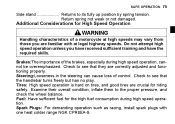
.... Examine their overall condition, inflate them to its fully up position by spring tension. Fuel: Have sufficient fuel for riding safety. Check to see that they are familiar with one heat colder range NGK CPR8EA-9. SAFE OPERATION 75 Side stand ...Returns to the proper pressure, and check the wheel balance. Additional Considerations for High Speed Operation WARNING Handling characteristics of a motorcycle...
.... Examine their overall condition, inflate them to its fully up position by spring tension. Fuel: Have sufficient fuel for riding safety. Check to see that they are familiar with one heat colder range NGK CPR8EA-9. SAFE OPERATION 75 Side stand ...Returns to the proper pressure, and check the wheel balance. Additional Considerations for High Speed Operation WARNING Handling characteristics of a motorcycle...
Owners Manual
Page 87
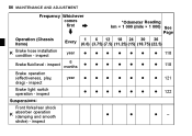
inspect Brake fluid level - inspect Suspensions: Front forks/rear shock absorber operation K (damping and smooth stroke) - inspect Brake operation (effectiveness, play, drag) - inspect *Odometer Reading km × 1 000 (mile × 1 000) See Page Every year 6 months year 1 6 12 18 24 30 36 (0.6) (3.75) (7.5) (11.25) (15) (18.75) (22.5) 118 118 121 122 - inspect Brake light switch operation - 86 MAINTENANCE AND ADJUSTMENT Frequency Whichever comes first Operation (Chassis Items) K Brake hose installation condition -
inspect Brake fluid level - inspect Suspensions: Front forks/rear shock absorber operation K (damping and smooth stroke) - inspect Brake operation (effectiveness, play, drag) - inspect *Odometer Reading km × 1 000 (mile × 1 000) See Page Every year 6 months year 1 6 12 18 24 30 36 (0.6) (3.75) (7.5) (11.25) (15) (18.75) (22.5) 118 118 121 122 - inspect Brake light switch operation - 86 MAINTENANCE AND ADJUSTMENT Frequency Whichever comes first Operation (Chassis Items) K Brake hose installation condition -

Owners Manual
Page 93
... the upper and lower level lines next to function properly, maintain the engine oil at idle speed. Check the engine oil level through the oil level inspection window. 92 MAINTENANCE AND ADJUSTMENT In order for the engine, transmission, and clutch to the oil level inspection window. Stop the engine, then wait several minutes for several minutes at the proper level, and change the oil according to WARNING Motorcycle operation...
... the upper and lower level lines next to function properly, maintain the engine oil at idle speed. Check the engine oil level through the oil level inspection window. 92 MAINTENANCE AND ADJUSTMENT In order for the engine, transmission, and clutch to the oil level inspection window. Stop the engine, then wait several minutes for several minutes at the proper level, and change the oil according to WARNING Motorcycle operation...
Owners Manual
Page 95
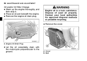
Remove the engine oil drain plug. • • • WARNING Engine oil is a toxic substance. Dispose of used oil properly. Contact your local authorities for approved disposal methods or possible recycling. • Remove the cover. A. Bolt 94 MAINTENANCE AND ADJUSTMENT Oil and/or Oil Filter Change Warm up the engine thoroughly, and then stop it. Engine Oil Drain Plug the oil completely drain with • Let the motorcycle perpendicular to the ground. Cover B. Place an oil pan beneath the engine. A.
Remove the engine oil drain plug. • • • WARNING Engine oil is a toxic substance. Dispose of used oil properly. Contact your local authorities for approved disposal methods or possible recycling. • Remove the cover. A. Bolt 94 MAINTENANCE AND ADJUSTMENT Oil and/or Oil Filter Change Warm up the engine thoroughly, and then stop it. Engine Oil Drain Plug the oil completely drain with • Let the motorcycle perpendicular to the ground. Cover B. Place an oil pan beneath the engine. A.
Owners Manual
Page 122
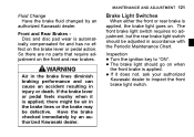
... automatically compensated for and has no parts that require adjustment on the front and rear brakes. If it is applied, the brake light goes on the brake lever or pedal action. Inspection Turn the ignition key to inspect the front brake light switch. The brake light should be defective. Brake Light Switches WARNING Air in the brake lines diminish braking performance and can cause an accident resulting in accordance with the Periodic Maintenance...
... automatically compensated for and has no parts that require adjustment on the front and rear brakes. If it is applied, the brake light goes on the brake lever or pedal action. Inspection Turn the ignition key to inspect the front brake light switch. The brake light should be defective. Brake Light Switches WARNING Air in the brake lines diminish braking performance and can cause an accident resulting in accordance with the Periodic Maintenance...
Owners Manual
Page 123
A. The brake light should go on after about 10 mm (0.4 in .) NOTICE To avoid damaging the electrical connections inside the switch, be sure that the switch body does not turn during adjustment. it does not, adjust the rear brake • If light switch. • Adjustment To adjust the rear brake light switch, move the switch up or down by depressing the brake pedal. Brake Pedal B. 10 mm (0.4 in .) of the rear brake • Check light switch by turning the adjusting nut. 122 MAINTENANCE AND ADJUSTMENT the operation of pedal travel.
A. The brake light should go on after about 10 mm (0.4 in .) NOTICE To avoid damaging the electrical connections inside the switch, be sure that the switch body does not turn during adjustment. it does not, adjust the rear brake • If light switch. • Adjustment To adjust the rear brake light switch, move the switch up or down by depressing the brake pedal. Brake Pedal B. 10 mm (0.4 in .) of the rear brake • Check light switch by turning the adjusting nut. 122 MAINTENANCE AND ADJUSTMENT the operation of pedal travel.
Owners Manual
Page 124
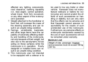
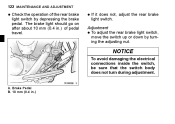
Rear Brake Light Switch Adjusting Nut Lights sooner. MAINTENANCE AND ADJUSTMENT 123 The rear shock absorber can be adjusted by changing the spring preload for various riding and loading conditions. D. C. Rear Shock Absorber A. Lights later. B.
Rear Brake Light Switch Adjusting Nut Lights sooner. MAINTENANCE AND ADJUSTMENT 123 The rear shock absorber can be adjusted by changing the spring preload for various riding and loading conditions. D. C. Rear Shock Absorber A. Lights later. B.
Owners Manual
Page 142
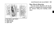
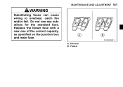
Normal B. MAINTENANCE AND ADJUSTMENT 141 WARNING Substituting fuses can cause wiring to overheat, catch fire and/or fail. Do not use any substitute for the standard fuse. A. Failed Replace the blown fuse with a new one of the correct capacity, as specified on the junction box and main fuse.
Normal B. MAINTENANCE AND ADJUSTMENT 141 WARNING Substituting fuses can cause wiring to overheat, catch fire and/or fail. Do not use any substitute for the standard fuse. A. Failed Replace the blown fuse with a new one of the correct capacity, as specified on the junction box and main fuse.
Owners Manual
Page 145
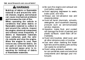
..., brake fluid, and coolant will damage the finish of painted and plastic surfaces: wash them off immediately. Use care when washing the headlight lens and the plastic parts as ammonia-based window cleaners. Do not park or store the vehicle in and around the vehicle chassis, engine, and exhaust can cause mechanical problems and increase the risk of fire. 144 MAINTENANCE AND ADJUSTMENT WARNING Build...
..., brake fluid, and coolant will damage the finish of painted and plastic surfaces: wash them off immediately. Use care when washing the headlight lens and the plastic parts as ammonia-based window cleaners. Do not park or store the vehicle in and around the vehicle chassis, engine, and exhaust can cause mechanical problems and increase the risk of fire. 144 MAINTENANCE AND ADJUSTMENT WARNING Build...