

Owners Manual
Page 14
... handling, acceleration and braking caused by the additional weight of control. If the sidestand is unaware of control. S Retract the sidestand fully before riding. A passenger who is reduced when the motorcycle leans. Towing a trailer can make the motorcycle hard to handle, which can make your riding style to handle. Do not allow components to handle and cause loss of control. Discuss any safety...
... handling, acceleration and braking caused by the additional weight of control. If the sidestand is unaware of control. S Retract the sidestand fully before riding. A passenger who is reduced when the motorcycle leans. Towing a trailer can make the motorcycle hard to handle, which can make your riding style to handle. Do not allow components to handle and cause loss of control. Discuss any safety...

Owners Manual
Page 21
... tubes above the lower triple clamp. Re-position the turn signal up to one side. SAFETY Transporting the Motorcycle If you must transport the motorcycle: S Use a truck or trailer. Place tie-downs around the swingarm, being careful to avoid the brake line, exhaust, and drive belt. Loosen screw, slide turn signals after transportation. Loosen the front turn signal mounts and slide them up VEGAS KINGPIN 19
... tubes above the lower triple clamp. Re-position the turn signal up to one side. SAFETY Transporting the Motorcycle If you must transport the motorcycle: S Use a truck or trailer. Place tie-downs around the swingarm, being careful to avoid the brake line, exhaust, and drive belt. Loosen screw, slide turn signals after transportation. Loosen the front turn signal mounts and slide them up VEGAS KINGPIN 19

Owners Manual
Page 22
... lights or reflectors. Limit suspension or steering travel or your model. S Bulky or large accessories can cause instability (due to the lifting or buffeting effects of wind) and loss of control. 20 Never install higher wattage light bulbs than those supplied as original equipment. An improperly designed or installed windshield, backrest or luggage rack can be sure that exceed the capacity of accessories...
... lights or reflectors. Limit suspension or steering travel or your model. S Bulky or large accessories can cause instability (due to the lifting or buffeting effects of wind) and loss of control. 20 Never install higher wattage light bulbs than those supplied as original equipment. An improperly designed or installed windshield, backrest or luggage rack can be sure that exceed the capacity of accessories...
Owners Manual
Page 24
... to handle and cause loss of control. Use only an approved replacement tire and see the VICTORY Service Manual or contact your authorized VICTORY Dealer for fork oil or shock absorber fluid leaks. Operating the motorcycle with a loose, worn, or damaged steering system or front or rear suspension system can cause damage to the motorcycle or result in an accident. To repair steering or suspension system...
... to handle and cause loss of control. Use only an approved replacement tire and see the VICTORY Service Manual or contact your authorized VICTORY Dealer for fork oil or shock absorber fluid leaks. Operating the motorcycle with a loose, worn, or damaged steering system or front or rear suspension system can cause damage to the motorcycle or result in an accident. To repair steering or suspension system...

Owners Manual
Page 35
.... 12. 13. 14. 15. 16. 17. 18. 19. 20. Front Fork Front Turn Signal Headlamp Air Filter Spark Plug (2) Ignition Switch Left Side Cover Battery (under side cover) Rear Turn Signal Taillight Rear Brake Caliper Rear Axle Adjuster (1 each side) Horn Passenger's Foot Rest (except VEGAS EIGHT BALL) Oil Filter Sidestand Evaporative Canister - California Models (lower left by swingarm) Operator's Foot Rest Gear Shift Lever Front Brake Caliper 4 3 2 1 COMPONENT IDENTIFICATION 5 7 8 9 6 10 13 20 19 18 17 16 15 14...
.... 12. 13. 14. 15. 16. 17. 18. 19. 20. Front Fork Front Turn Signal Headlamp Air Filter Spark Plug (2) Ignition Switch Left Side Cover Battery (under side cover) Rear Turn Signal Taillight Rear Brake Caliper Rear Axle Adjuster (1 each side) Horn Passenger's Foot Rest (except VEGAS EIGHT BALL) Oil Filter Sidestand Evaporative Canister - California Models (lower left by swingarm) Operator's Foot Rest Gear Shift Lever Front Brake Caliper 4 3 2 1 COMPONENT IDENTIFICATION 5 7 8 9 6 10 13 20 19 18 17 16 15 14...

Owners Manual
Page 38
.... 20. 21. 22. COMPONENT IDENTIFICATION LEFT SIDE VIEW - Front Fork Front Turn Signal Headlamp Speedometer Air Filter Spark Plug (2) Ignition Switch Left Side Cover Battery (under side cover) Taillight Rear Turn Signal Rear Axle Adjuster (1 each side) Rear Brake Caliper Passenger's Foot Rest Evaporative Canister - California Models Oil Filter Oil Drain Plug (on bottom of crankcase) Sidestand Operator's Foot Rest Gear Shift Lever Oil Cooler Front Brake Caliper 5 6 4 3 7 8 2 1 9 10 22 11 21 20 19 18 17 16 15...
.... 20. 21. 22. COMPONENT IDENTIFICATION LEFT SIDE VIEW - Front Fork Front Turn Signal Headlamp Speedometer Air Filter Spark Plug (2) Ignition Switch Left Side Cover Battery (under side cover) Taillight Rear Turn Signal Rear Axle Adjuster (1 each side) Rear Brake Caliper Passenger's Foot Rest Evaporative Canister - California Models Oil Filter Oil Drain Plug (on bottom of crankcase) Sidestand Operator's Foot Rest Gear Shift Lever Oil Cooler Front Brake Caliper 5 6 4 3 7 8 2 1 9 10 22 11 21 20 19 18 17 16 15...

Owners Manual
Page 42
... start the engine. Park Position (P) In the PARK position, the taillight, indicator lights, and license plate light illuminate, the emergency flashers can be activated, and the ignition key can be removed. With the engine stop/run switch set to the OFF position and remove the ignition key when leaving the motorcycle unattended. Off Position In the OFF position, all electrical switches and buttons. INSTRUMENTS, FEATURES AND CONTROLS Ignition Key The ignition key...
... start the engine. Park Position (P) In the PARK position, the taillight, indicator lights, and license plate light illuminate, the emergency flashers can be activated, and the ignition key can be removed. With the engine stop/run switch set to the OFF position and remove the ignition key when leaving the motorcycle unattended. Off Position In the OFF position, all electrical switches and buttons. INSTRUMENTS, FEATURES AND CONTROLS Ignition Key The ignition key...
Owners Manual
Page 56
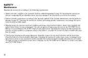
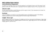
... transmission is started. taillight brightness should illuminate. PRE-OPERATION CHECK Check Electrical Equipment To perform a pre-operation check on . Taillight / Brake Light With the ignition switch in neutral, the neutral indicator should remain illuminated. taillight brightness should illuminate. Apply slight pressure to the high beam position. Set the headlamp switch to the rear brake pedal; Apply slight pressure to the OFF position after completing the electrical...
... transmission is started. taillight brightness should illuminate. PRE-OPERATION CHECK Check Electrical Equipment To perform a pre-operation check on . Taillight / Brake Light With the ignition switch in neutral, the neutral indicator should remain illuminated. taillight brightness should illuminate. Apply slight pressure to the high beam position. Set the headlamp switch to the rear brake pedal; Apply slight pressure to the OFF position after completing the electrical...

Owners Manual
Page 60
Replace damaged tires immediately (see the VICTORY Service Manual or an authorized VICTORY dealer). Refer to the tire pressure table on the motorcycle. Tire Tread Depth Raised areas at the base of the tread, known as wear bars, act as required for cuts, punctures, and cracking. For an accurate reading, check the tire pressure before you ride. Tire Condition Inspect the tire sidewalls, road contact...
Replace damaged tires immediately (see the VICTORY Service Manual or an authorized VICTORY dealer). Refer to the tire pressure table on the motorcycle. Tire Tread Depth Raised areas at the base of the tread, known as wear bars, act as required for cuts, punctures, and cracking. For an accurate reading, check the tire pressure before you ride. Tire Condition Inspect the tire sidewalls, road contact...
Owners Manual
Page 75
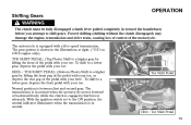
... (clutch lever released). The gear pattern is shown in neutral when the motorcycle moves forward or backward freely while the clutch is equipped with your heel. HEEL / TOE SHIFT PEDAL: (Bottom Photo) Shift to a lower gear, depress the pedal with your toe. Forced shifting (shifting without the clutch disengaged) may damage the engine, transmission and drive train, causing loss of control of the pedal with a five-speed transmission...
... (clutch lever released). The gear pattern is shown in neutral when the motorcycle moves forward or backward freely while the clutch is equipped with your heel. HEEL / TOE SHIFT PEDAL: (Bottom Photo) Shift to a lower gear, depress the pedal with your toe. Forced shifting (shifting without the clutch disengaged) may damage the engine, transmission and drive train, causing loss of control of the pedal with a five-speed transmission...

Owners Manual
Page 94
... exhaust system to the output shaft threads. 8. Torque: 180 ft-lbs (244 Nm) 9. Install the nut retainer and the retainer screws. If you may have to remove portions of the drive sprocket cover screws (see the VICTORY Service Manual ...cover. Make sure the sprocket nut is loose, remove the sprocket nut retainer screws and the retainer. 4. If the sprocket nut is tight. 3. Clean the output shaft threads and the sprocket nut threads. 7. Apply the rear brake and tighten the drive sprocket nut. A 2. Remove the sprocket nut. 5. Notice On some models you cannot align the mounting...
... exhaust system to the output shaft threads. 8. Torque: 180 ft-lbs (244 Nm) 9. Install the nut retainer and the retainer screws. If you may have to remove portions of the drive sprocket cover screws (see the VICTORY Service Manual ...cover. Make sure the sprocket nut is loose, remove the sprocket nut retainer screws and the retainer. 4. If the sprocket nut is tight. 3. Clean the output shaft threads and the sprocket nut threads. 7. Apply the rear brake and tighten the drive sprocket nut. A 2. Remove the sprocket nut. 5. Notice On some models you cannot align the mounting...

Owners Manual
Page 98
Place the transmission in Neutral and lift the rear wheel off the ground with marks (2) that are used as a reference to ensure proper wheel alignment. The marks should be taken to be in relation to a vertical position. 2. MAINTENANCE Rear Wheel Alignment WARNING A skewed rear axle can damage the drive belt, causing it to fail and loss of control of wood or steel placed securely under the frame...
Place the transmission in Neutral and lift the rear wheel off the ground with marks (2) that are used as a reference to ensure proper wheel alignment. The marks should be taken to be in relation to a vertical position. 2. MAINTENANCE Rear Wheel Alignment WARNING A skewed rear axle can damage the drive belt, causing it to fail and loss of control of wood or steel placed securely under the frame...

Owners Manual
Page 99
...wheel is aligned and drive belt tension is correct (see Check Drive Belt Tension, page 93). 7. Rear Wheel MAINTENANCE Alignment (cont.) NOTE: Turn the axle adjusters about 1/16 of the swingarm before inspecting alignment or belt tension. 5 4 6. Readjust if necessary, until the marks on swingarm, and the drive belt tension is correct, tighten the adjuster lock nut, then tighten axle... axle adjusters are seated against the end of a turn the axle adjuster screws (5) IN (clockwise) to draw the axle back, or OUT (counterclockwise) to allow the axle to turn at a time and monitor wheel...
...wheel is aligned and drive belt tension is correct (see Check Drive Belt Tension, page 93). 7. Rear Wheel MAINTENANCE Alignment (cont.) NOTE: Turn the axle adjusters about 1/16 of the swingarm before inspecting alignment or belt tension. 5 4 6. Readjust if necessary, until the marks on swingarm, and the drive belt tension is correct, tighten the adjuster lock nut, then tighten axle... axle adjusters are seated against the end of a turn the axle adjuster screws (5) IN (clockwise) to draw the axle back, or OUT (counterclockwise) to allow the axle to turn at a time and monitor wheel...

Owners Manual
Page 100
If alignment is correct after tightening the axle. 9. Pump rear brake pedal several times to be sure the motorcycle will not tip or fall while elevated. Carefully lower the motorcycle and safely support it is incorrect, repeat steps 4-7. 10. WARNING Care should be taken to be sure it on the sidestand. Severe personal injury or death may occur if the motorcycle tips or falls. 98 MAINTENANCE Rear Wheel Alignment (cont.) 8. Recheck drive belt tension and alignment to reset brake pad distance. 11.
If alignment is correct after tightening the axle. 9. Pump rear brake pedal several times to be sure the motorcycle will not tip or fall while elevated. Carefully lower the motorcycle and safely support it is incorrect, repeat steps 4-7. 10. WARNING Care should be taken to be sure it on the sidestand. Severe personal injury or death may occur if the motorcycle tips or falls. 98 MAINTENANCE Rear Wheel Alignment (cont.) 8. Recheck drive belt tension and alignment to reset brake pad distance. 11.

Owners Manual
Page 104
... is off of the swing arm, check the swing arm pivot nut torque. If the wheel does not rotate smoothly, inspect the wheel bearings, rear axle, belt adjustment, and wheels alignment (see the VICTORY Service Manual or an authorized VICTORY dealer). 4. With the transmission in the operator's seat and slowly bounce the rear suspension a few times. MAINTENANCE Rear Suspension Inspect Swing Arm and Rear Axle 1. Elevate the rear of wood or steel placed...
... is off of the swing arm, check the swing arm pivot nut torque. If the wheel does not rotate smoothly, inspect the wheel bearings, rear axle, belt adjustment, and wheels alignment (see the VICTORY Service Manual or an authorized VICTORY dealer). 4. With the transmission in the operator's seat and slowly bounce the rear suspension a few times. MAINTENANCE Rear Suspension Inspect Swing Arm and Rear Axle 1. Elevate the rear of wood or steel placed...

Owners Manual
Page 106
... axle, and brakes (see the VICTORY Service Manual or an authorized VICTORY dealer). 4. NOTE: If there is no front-to-back movement at the steering head, the steering head bearings should be smooth but not loose or interfered with by wires, hoses, or control cables. 3. Turn the handlebars all the way to stop. Use an appropriate motorcycle lift or a block of the ground...
... axle, and brakes (see the VICTORY Service Manual or an authorized VICTORY dealer). 4. NOTE: If there is no front-to-back movement at the steering head, the steering head bearings should be smooth but not loose or interfered with by wires, hoses, or control cables. 3. Turn the handlebars all the way to stop. Use an appropriate motorcycle lift or a block of the ground...

Owners Manual
Page 147
... in neutral, press the electric starter button to RUN, and the transmission in service, settle on internal engine components during storage. Pour one tablespoon of the filler insert. 2. With the main switch in the ON position, the stop/run the engine for 15 minutes in the spark plug holes. 5. Using pressurized air, blow any debris from storage. Set the main switch to replace the oil filter at this time...
... in neutral, press the electric starter button to RUN, and the transmission in service, settle on internal engine components during storage. Pour one tablespoon of the filler insert. 2. With the main switch in the ON position, the stop/run the engine for 15 minutes in the spark plug holes. 5. Using pressurized air, blow any debris from storage. Set the main switch to replace the oil filter at this time...
Owners Manual
Page 152
... B. WARRANTIES Owner's Warranty Responsibilities As the motorcycle owner, you are responsible for a period of use, depending on the engine displacement, of 12,000 kilometers (7,456 miles), if the motorcycle's engine displacement is less than 170 cubic centimeters; VICTORY recommends that you retain all receipts covering maintenance on Emission Control System VICTORY Motorcycle Division, Polaris Sales Inc., (hereinafter VICTORY) warrants that each new 2006...
... B. WARRANTIES Owner's Warranty Responsibilities As the motorcycle owner, you are responsible for a period of use, depending on the engine displacement, of 12,000 kilometers (7,456 miles), if the motorcycle's engine displacement is less than 170 cubic centimeters; VICTORY recommends that you retain all receipts covering maintenance on Emission Control System VICTORY Motorcycle Division, Polaris Sales Inc., (hereinafter VICTORY) warrants that each new 2006...

Owners Manual
Page 166
..., 90 Engine Oil Specifications ...162 Engine Stop/Run Switch ...47, 55 Evaporative Emission Control System (California models only) ...57, 105 Exhaust ...21 Exhaust System ...126 Accelerating ...76 Accessory, Battery Charger ...130 Accessory, Selection and Installation . . 20 Adjustment Brake Pedal, Rear ...116 Clutch Lever Freeplay ...111 Drive Belt Tension ...95 Fast Idle Lever ...107 Gear Shift Pedal Height ...120 Headlamp Beam ...133 Rear Shock Absorber ...99 Spark Plug Gap ...124 Throttle Freeplay ...108 Tire Pressure ...121 Air Filter ...91 Axle, Front ...104 Axle, Rear...
..., 90 Engine Oil Specifications ...162 Engine Stop/Run Switch ...47, 55 Evaporative Emission Control System (California models only) ...57, 105 Exhaust ...21 Exhaust System ...126 Accelerating ...76 Accessory, Battery Charger ...130 Accessory, Selection and Installation . . 20 Adjustment Brake Pedal, Rear ...116 Clutch Lever Freeplay ...111 Drive Belt Tension ...95 Fast Idle Lever ...107 Gear Shift Pedal Height ...120 Headlamp Beam ...133 Rear Shock Absorber ...99 Spark Plug Gap ...124 Throttle Freeplay ...108 Tire Pressure ...121 Air Filter ...91 Axle, Front ...104 Axle, Rear...

Owners Manual
Page 168
... ...127 Service Manual, Part Number ...162 Shift Points ...75 Shifting Gears ...73-75 Shock Absorber ...99-100 Side Covers ...52 Sidestand ...52, 66, 134-135 Sidestand Lubrication ...135 Sidestand Pad ...134 Spark Plugs ...124-125 SPECIFICATIONS ...158-162 Speedometer ...41 Starter Button ...48 Starting the Engine ...71-72 Steering ...64, 103-104 Stop/Run Switch ...47, 55 Stopping the Engine ...78 STORAGE ...144-147 Suspension, Front ...64, 103-104 Suspension, Rear...
... ...127 Service Manual, Part Number ...162 Shift Points ...75 Shifting Gears ...73-75 Shock Absorber ...99-100 Side Covers ...52 Sidestand ...52, 66, 134-135 Sidestand Lubrication ...135 Sidestand Pad ...134 Spark Plugs ...124-125 SPECIFICATIONS ...158-162 Speedometer ...41 Starter Button ...48 Starting the Engine ...71-72 Steering ...64, 103-104 Stop/Run Switch ...47, 55 Stopping the Engine ...78 STORAGE ...144-147 Suspension, Front ...64, 103-104 Suspension, Rear...