

Owners Manual
Page 16
... hard to contact the road surface when leaning the motorcycle in handling, acceleration and braking caused by the additional weight of the passenger. S Before riding, be sure your passenger. A passenger who is reduced when the motorcycle leans. Safe Riding Practices SAFETY S Ground clearance is not holding on properly, or who cannot reach the passenger footrests, can shift their body erratically, which could...
... hard to contact the road surface when leaning the motorcycle in handling, acceleration and braking caused by the additional weight of the passenger. S Before riding, be sure your passenger. A passenger who is reduced when the motorcycle leans. Safe Riding Practices SAFETY S Ground clearance is not holding on properly, or who cannot reach the passenger footrests, can shift their body erratically, which could...

Owners Manual
Page 23
... turn signal mounts and slide them up VEGAS 18 KINGPIN SAFETY Transporting the Motorcycle If you must transport the motorcycle: S Use a truck or trailer. Secure the rear of the motorcycle with another vehicle, as gasoline may leak out of control. Loosen screw, slide turn signals after transportation. Gasoline is a fire hazard and it remains upright on the truck or trailer, as towing will impair the motorcycle's steering and handling...
... turn signal mounts and slide them up VEGAS 18 KINGPIN SAFETY Transporting the Motorcycle If you must transport the motorcycle: S Use a truck or trailer. Secure the rear of the motorcycle with another vehicle, as gasoline may leak out of control. Loosen screw, slide turn signals after transportation. Gasoline is a fire hazard and it remains upright on the truck or trailer, as towing will impair the motorcycle's steering and handling...
Owners Manual
Page 24
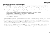
... the instructions for your model. Before installing an accessory, be safely operated with any accessories or additional weight. An electrical failure could result and cause hazardous loss of engine power or lights or damage to add a windshield, backrest or luggage rack, choose one designed and approved by VICTORY specifically for proper installation and use. Accessory Selection and Installation SAFETY Because VICTORY cannot test...
... the instructions for your model. Before installing an accessory, be safely operated with any accessories or additional weight. An electrical failure could result and cause hazardous loss of engine power or lights or damage to add a windshield, backrest or luggage rack, choose one designed and approved by VICTORY specifically for proper installation and use. Accessory Selection and Installation SAFETY Because VICTORY cannot test...
Owners Manual
Page 26
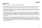
S Maintain proper tire pressure and tread condition and proper wheel and tire balance. Operating the motorcycle with a loose, worn, or damaged steering system or front or rear suspension system can cause damage to handle and cause loss of control. S Check proper steering head bearing adjustment. To repair steering or suspension system wear or damage, see the VICTORY Service Manual or your authorized VICTORY Dealer. 21 S Perform periodic maintenance according to...
S Maintain proper tire pressure and tread condition and proper wheel and tire balance. Operating the motorcycle with a loose, worn, or damaged steering system or front or rear suspension system can cause damage to handle and cause loss of control. S Check proper steering head bearing adjustment. To repair steering or suspension system wear or damage, see the VICTORY Service Manual or your authorized VICTORY Dealer. 21 S Perform periodic maintenance according to...

Owners Manual
Page 39
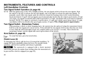
... LEFT SIDE VIEW - California Models Oil Filter Oil Drain Plug (on bottom of crankcase) Sidestand Operator's Foot Rest Gear Shift Lever Oil Cooler Front Brake Caliper 5 6 4 3 7 8 2 1 9 10 11 22 21 20 19 18 17 16 15 14 13 12 34 Front Fork Front Turn Signal Headlamp Speedometer Air Filter Spark Plug (2) Ignition Switch Left Side Cover Battery (under side cover) Taillight Rear Turn Signal Rear Axle Adjuster (1 each side) Rear Brake Caliper Passenger's Foot Rest Evaporative Canister - KINGPIN...
... LEFT SIDE VIEW - California Models Oil Filter Oil Drain Plug (on bottom of crankcase) Sidestand Operator's Foot Rest Gear Shift Lever Oil Cooler Front Brake Caliper 5 6 4 3 7 8 2 1 9 10 11 22 21 20 19 18 17 16 15 14 13 12 34 Front Fork Front Turn Signal Headlamp Speedometer Air Filter Spark Plug (2) Ignition Switch Left Side Cover Battery (under side cover) Taillight Rear Turn Signal Rear Axle Adjuster (1 each side) Rear Brake Caliper Passenger's Foot Rest Evaporative Canister - KINGPIN...

Owners Manual
Page 43
... are inactive and the ignition key can also activate the emergency flashers, turn signals and all electrical switches and buttons. The headlamp, taillight, and instrument lights illuminate. You must push the ignition key into the switch while selecting the Park position. 38 INSTRUMENTS, FEATURES AND CONTROLS Ignition Key The ignition key operates the ignition switch and parking lights. With the engine stop/run switch set to the OFF position and remove the ignition key when leaving the motorcycle...
... are inactive and the ignition key can also activate the emergency flashers, turn signals and all electrical switches and buttons. The headlamp, taillight, and instrument lights illuminate. You must push the ignition key into the switch while selecting the Park position. 38 INSTRUMENTS, FEATURES AND CONTROLS Ignition Key The ignition key operates the ignition switch and parking lights. With the engine stop/run switch set to the OFF position and remove the ignition key when leaving the motorcycle...
Owners Manual
Page 49
... a vehicle or when changing lanes, the operator has the option of the switch. Momentary Feature Horn Button (4, page 43) Clutch Lever (5) To disengage the clutch, pull the lever (5) toward the housing when in the centered position. To engage the clutch, gradually release the lever. INSTRUMENTS, FEATURES AND CONTROLS Left Handlebar Controls Turn Signal Switch Operation (3, page 43) With the ignition key in the ON or PARK position, the turn signal switch activates the turn signals...
... a vehicle or when changing lanes, the operator has the option of the switch. Momentary Feature Horn Button (4, page 43) Clutch Lever (5) To disengage the clutch, pull the lever (5) toward the housing when in the centered position. To engage the clutch, gradually release the lever. INSTRUMENTS, FEATURES AND CONTROLS Left Handlebar Controls Turn Signal Switch Operation (3, page 43) With the ignition key in the ON or PARK position, the turn signal switch activates the turn signals...

Owners Manual
Page 57
... oil pressure indicator should illuminate. The headlamp brightness should increase and the headlamp high beam indicator light should illuminate until the engine is started. Set the ignition switch to the front brake lever; Set the headlamp switch to the rear brake pedal; Apply slight pressure to the high beam position. PRE-OPERATION CHECK Check Electrical Equipment To perform a pre-operation check on . If the transmission...
... oil pressure indicator should illuminate. The headlamp brightness should increase and the headlamp high beam indicator light should illuminate until the engine is started. Set the ignition switch to the front brake lever; Set the headlamp switch to the rear brake pedal; Apply slight pressure to the high beam position. PRE-OPERATION CHECK Check Electrical Equipment To perform a pre-operation check on . If the transmission...

Owners Manual
Page 61
... tire pressure before you ride. Tire Condition Inspect the tire sidewalls, road contact surface, and tread base for the total weight of the wear bars, replace the tire. 56 When the road contact surface has worn to the decal on page 118, or to the top of your intended load. PRE-OPERATION CHECK Check Tires Tire Pressure Normal riding warms the tires and increases the tire air pressure...
... tire pressure before you ride. Tire Condition Inspect the tire sidewalls, road contact surface, and tread base for the total weight of the wear bars, replace the tire. 56 When the road contact surface has worn to the decal on page 118, or to the top of your intended load. PRE-OPERATION CHECK Check Tires Tire Pressure Normal riding warms the tires and increases the tire air pressure...
Owners Manual
Page 76
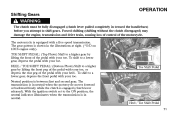
.... To shift to shift gears. Forced shifting (shifting without the clutch disengaged) may damage the engine, transmission and drive train, causing loss of control of the motorcycle. The motorcycle is between first and second gear. Neutral position is equipped with a five-speed transmission. The transmission is engaged (clutch lever released). Shifting Gears WARNING OPERATION The clutch must be fully disengaged (clutch lever pulled completely in toward the handlebars) before you attempt to a lower gear...
.... To shift to shift gears. Forced shifting (shifting without the clutch disengaged) may damage the engine, transmission and drive train, causing loss of control of the motorcycle. The motorcycle is between first and second gear. Neutral position is equipped with a five-speed transmission. The transmission is engaged (clutch lever released). Shifting Gears WARNING OPERATION The clutch must be fully disengaged (clutch lever pulled completely in toward the handlebars) before you attempt to a lower gear...

Owners Manual
Page 81
... motion and the transmission is engaged may lose control. • If the motorcycle is not already in neutral, shift into neutral. To stop the engine, set the engine stop/run switch to the STOP position, turn the ignition switch to the OFF position, and remove the ignition key. Once the motorcycle is at a complete stop, if it is in neutral or with the clutch disengaged. In...
... motion and the transmission is engaged may lose control. • If the motorcycle is not already in neutral, shift into neutral. To stop the engine, set the engine stop/run switch to the STOP position, turn the ignition switch to the OFF position, and remove the ignition key. Once the motorcycle is at a complete stop, if it is in neutral or with the clutch disengaged. In...

Owners Manual
Page 95
... 1 2 4 WARNING Care should be replaced at the time of damage or failure. Replace drive belt and both sprockets as a set if drive belt has over 5,000 miles (8,000 km) of wood or steel placed securely under the frame. 3 1. 2. 3. 4. PV-43532, which is properly adjusted (see the VICTORY Service Manual or an authorized VICTORY dealer). Place the transmission in Neutral and lift the rear wheel off the ground...
... 1 2 4 WARNING Care should be replaced at the time of damage or failure. Replace drive belt and both sprockets as a set if drive belt has over 5,000 miles (8,000 km) of wood or steel placed securely under the frame. 3 1. 2. 3. 4. PV-43532, which is properly adjusted (see the VICTORY Service Manual or an authorized VICTORY dealer). Place the transmission in Neutral and lift the rear wheel off the ground...

Owners Manual
Page 99
MAINTENANCE Rear Wheel Alignment (cont.) NOTE: Turn the axle adjusters about 1/16 of the swingarm before inspecting alignment or belt tension. 6. When wheel is aligned and drive belt tension is correct (see Check Drive Belt Tension, page 90). 7. Recheck rear wheel alignment as you proceed. 5. On screw style adjusters: Use a 17mm wrench to loosen lock nut (4), then an 8mm hexagonal wrench to turn the axle adjuster screws...
MAINTENANCE Rear Wheel Alignment (cont.) NOTE: Turn the axle adjusters about 1/16 of the swingarm before inspecting alignment or belt tension. 6. When wheel is aligned and drive belt tension is correct (see Check Drive Belt Tension, page 90). 7. Recheck rear wheel alignment as you proceed. 5. On screw style adjusters: Use a 17mm wrench to loosen lock nut (4), then an 8mm hexagonal wrench to turn the axle adjuster screws...

Owners Manual
Page 104
... of the ground. Sit in neutral, slowly rotate the rear wheel. Grasp the rear tire and attempt to move the rear wheel side-to-side. Rear Suspension MAINTENANCE Inspect Swing Arm and Rear Axle 1. NOTE: If there is still present, inspect the swing arm pivot bushings (see the VICTORY Service Manual or an authorized VICTORY dealer). 4. If the wheel does not rotate smoothly, inspect the wheel bearings, rear axle, belt adjustment, and wheels alignment...
... of the ground. Sit in neutral, slowly rotate the rear wheel. Grasp the rear tire and attempt to move the rear wheel side-to-side. Rear Suspension MAINTENANCE Inspect Swing Arm and Rear Axle 1. NOTE: If there is still present, inspect the swing arm pivot bushings (see the VICTORY Service Manual or an authorized VICTORY dealer). 4. If the wheel does not rotate smoothly, inspect the wheel bearings, rear axle, belt adjustment, and wheels alignment...

Owners Manual
Page 106
...). 101 Turn the handlebars from stop to -back. Point the front wheel straight ahead. Slowly rotate the front wheel. Front Suspension and Steering WARNING MAINTENANCE Care should be taken to be smooth but not loose or interfered with by wires, hoses, or control cables. 3. Severe personal injury or death may occur if the motorcycle tips or falls. Inspect Steering and Front Axle...
...). 101 Turn the handlebars from stop to -back. Point the front wheel straight ahead. Slowly rotate the front wheel. Front Suspension and Steering WARNING MAINTENANCE Care should be taken to be smooth but not loose or interfered with by wires, hoses, or control cables. 3. Severe personal injury or death may occur if the motorcycle tips or falls. Inspect Steering and Front Axle...
Owners Manual
Page 109
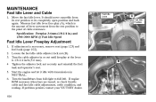
... adjuster in NEUTRAL. 6. Turn the handlebars from full right to the point of cable resistance. Specification: Freeplay 3-6mm (1/8-1/4 in.) and 1500-3000 RPM @ Fast Idle Speed Fast Idle Lever A Fast Idle Position Fast Idle Lever Freeplay Adjustment 1. If engine RPM increases when bars are turned, re-check throttle cable and fast idle cable adjustments, cable condition, and routing. Loosen the fast idle cable adjuster lock nut...
... adjuster in NEUTRAL. 6. Turn the handlebars from full right to the point of cable resistance. Specification: Freeplay 3-6mm (1/8-1/4 in.) and 1500-3000 RPM @ Fast Idle Speed Fast Idle Lever A Fast Idle Position Fast Idle Lever Freeplay Adjustment 1. If engine RPM increases when bars are turned, re-check throttle cable and fast idle cable adjustments, cable condition, and routing. Loosen the fast idle cable adjuster lock nut...

Owners Manual
Page 146
... engine a few times. Pour one tablespoon of clean motor oil into each spark plug. Connect the spark plugs to the spark plug wires and ground the spark plugs to the OFF position and reinstall the spark plugs. 141 With the main switch in the ON position, the stop/run the engine for 15 minutes in the spark plug holes. 5. Fuel Stabilizer STORAGE 1. Carbon deposits, normally suspended in engine oil that is in neutral, press the electric starter...
... engine a few times. Pour one tablespoon of clean motor oil into each spark plug. Connect the spark plugs to the spark plug wires and ground the spark plugs to the OFF position and reinstall the spark plugs. 141 With the main switch in the ON position, the stop/run the engine for 15 minutes in the spark plug holes. 5. Fuel Stabilizer STORAGE 1. Carbon deposits, normally suspended in engine oil that is in neutral, press the electric starter...
Owners Manual
Page 151
The warranty repairs should be aware that VICTORY may deny your warranty coverage if your motorcycle or part has failed due to exceed 30 days. As the motorcycle owner, you retain all receipts covering maintenance on your motorcycle to ensure the performance of all applicable regulations of time, not to abuse, neglect, improper maintenance or unapproved modifications. is designed, built and...
The warranty repairs should be aware that VICTORY may deny your warranty coverage if your motorcycle or part has failed due to exceed 30 days. As the motorcycle owner, you retain all receipts covering maintenance on your motorcycle to ensure the performance of all applicable regulations of time, not to abuse, neglect, improper maintenance or unapproved modifications. is designed, built and...

Owners Manual
Page 166
... Front Brake Lever ...46 Fork Oil / Forks ...100 Fuel ...20 Fuel Cap ...49 Fuel Filter ...103 Fuel Level ...55 Fuel Specifications ...158 Fuel System ...102-103 Fuel Tank Removal / Installation ...102 Fuel Hose, Rail, Connections ...55, 102 Fuel Stabilizer ...141 Fueling and Fill Height ...68 Fuel System Priming ...68 Fuses ...128 H INDEX E Electrical Equipment ...52-53 Emergency Flasher Switch ...45 Emissions Control System Warranty . 145 Engine Break-in Period ...66-70 Engine Compression ...122 Engine Identification...
... Front Brake Lever ...46 Fork Oil / Forks ...100 Fuel ...20 Fuel Cap ...49 Fuel Filter ...103 Fuel Level ...55 Fuel Specifications ...158 Fuel System ...102-103 Fuel Tank Removal / Installation ...102 Fuel Hose, Rail, Connections ...55, 102 Fuel Stabilizer ...141 Fueling and Fill Height ...68 Fuel System Priming ...68 Fuses ...128 H INDEX E Electrical Equipment ...52-53 Emergency Flasher Switch ...45 Emissions Control System Warranty . 145 Engine Break-in Period ...66-70 Engine Compression ...122 Engine Identification...

Owners Manual
Page 167
...-88 Oil Specifications ...158 Overdrive Indicator Lamp ...40 R Rear Shock Absorber ...97-98 Recommended Oil ...87 Recommended Shift Points ...73 Registration ...151 Removal from Storage ...143 Repairing Painted Surface Damage . . 139 Reporting Safety Defects ...29 Right Side Views ...32, 35 Road Test ...132 Key Number, Ignition ...37 Left Side Views ...31, 34 Loading Examples ...14, 15 Low Fuel Indicator ...42 Low Oil Pressure Indicator ...42 M Maintenance...
...-88 Oil Specifications ...158 Overdrive Indicator Lamp ...40 R Rear Shock Absorber ...97-98 Recommended Oil ...87 Recommended Shift Points ...73 Registration ...151 Removal from Storage ...143 Repairing Painted Surface Damage . . 139 Reporting Safety Defects ...29 Right Side Views ...32, 35 Road Test ...132 Key Number, Ignition ...37 Left Side Views ...31, 34 Loading Examples ...14, 15 Low Fuel Indicator ...42 Low Oil Pressure Indicator ...42 M Maintenance...