

Owners Manual
Page 16
Safe Riding Practices SAFETY S Ground clearance is not holding on properly, or who cannot reach the passenger footrests, can shift their body erratically, which could contact the road surface and cause loss of control. To carry a passenger safely, do so can cause loss of control. 11 S Before riding, be sure your passenger. Discuss any safety information unfamiliar to handle and can cause loss...
Safe Riding Practices SAFETY S Ground clearance is not holding on properly, or who cannot reach the passenger footrests, can shift their body erratically, which could contact the road surface and cause loss of control. To carry a passenger safely, do so can cause loss of control. 11 S Before riding, be sure your passenger. Discuss any safety information unfamiliar to handle and can cause loss...

Owners Manual
Page 24
... careful to avoid the brake line, exhaust, and drive belt. Do not tow the motorcycle with tiedowns around the fork tubes above the lower triple clamp. S Do not restrain the motorcycle using the handlebars. Secure the rear of the motorcycle with another vehicle, as gasoline may leak out of control. Reposition the turn signal mounts and slide them up KINGPIN VEGAS 19 S Position and...
... careful to avoid the brake line, exhaust, and drive belt. Do not tow the motorcycle with tiedowns around the fork tubes above the lower triple clamp. S Do not restrain the motorcycle using the handlebars. Secure the rear of the motorcycle with another vehicle, as gasoline may leak out of control. Reposition the turn signal mounts and slide them up KINGPIN VEGAS 19 S Position and...
Owners Manual
Page 25
S Do not install electrical accessories that exceed the capacity of the motorcycle. Limit suspension or steering travel or your model. Never install higher wattage light bulbs than those supplied as original equipment. An improperly designed or installed windshield, backrest or luggage rack can cause instability (due to the electrical system. Follow the instructions for determining that the motorcycle can be sure that...
S Do not install electrical accessories that exceed the capacity of the motorcycle. Limit suspension or steering travel or your model. Never install higher wattage light bulbs than those supplied as original equipment. An improperly designed or installed windshield, backrest or luggage rack can cause instability (due to the electrical system. Follow the instructions for determining that the motorcycle can be sure that...
Owners Manual
Page 27
.... S Perform periodic maintenance according to handle and cause loss of control. Use only an approved replacement tire and see the VICTORY Service Manual or contact your authorized VICTORY Dealer for fork oil or shock absorber fluid leaks. To repair steering or suspension system wear or damage, see the VICTORY Service Manual or your authorized VICTORY Dealer. 22 S Maintain proper tire pressure and tread condition and proper wheel and tire balance. Inspect tires regularly...
.... S Perform periodic maintenance according to handle and cause loss of control. Use only an approved replacement tire and see the VICTORY Service Manual or contact your authorized VICTORY Dealer for fork oil or shock absorber fluid leaks. To repair steering or suspension system wear or damage, see the VICTORY Service Manual or your authorized VICTORY Dealer. 22 S Maintain proper tire pressure and tread condition and proper wheel and tire balance. Inspect tires regularly...

Owners Manual
Page 40
KINGPIN Models 1. 2. 3. 4. 5. 6. 7. 8. 9. 10. 11. 12. 13. 14. 15. 16. 17. 18. 19. 20. 21. Front Fork Front Turn Signal Headlamp Speedometer Air Filter Spark Plug (2) Ignition Switch Left Side Cover Battery (under side cover) Taillight Rear Turn Signal Rear Axle Adjuster (1 each side) Rear Brake Caliper Passenger's Foot Rest (passenger models) Evaporative Canister (California Models) Oil Filter Oil Drain Plug (on bottom of crankcase) Sidestand Operator's Foot Rest Gear Shift Lever Front Brake Caliper 4 3 COMPONENT IDENTIFICATION 5 6 7 8 2 1 9 10 11 21 20 19 18...
KINGPIN Models 1. 2. 3. 4. 5. 6. 7. 8. 9. 10. 11. 12. 13. 14. 15. 16. 17. 18. 19. 20. 21. Front Fork Front Turn Signal Headlamp Speedometer Air Filter Spark Plug (2) Ignition Switch Left Side Cover Battery (under side cover) Taillight Rear Turn Signal Rear Axle Adjuster (1 each side) Rear Brake Caliper Passenger's Foot Rest (passenger models) Evaporative Canister (California Models) Oil Filter Oil Drain Plug (on bottom of crankcase) Sidestand Operator's Foot Rest Gear Shift Lever Front Brake Caliper 4 3 COMPONENT IDENTIFICATION 5 6 7 8 2 1 9 10 11 21 20 19 18...

Owners Manual
Page 41
Passenger's Seat (passenger models) Seat Strap Operator's Seat Rear Shock Absorber (access through RH side cover) Side Cover Engine Oil Fill Cap/Dipstick Front Brake Lever Front Turn Signal Horn Front Fork Rear Brake Pedal Operator's Foot Rest Rear Brake Fluid Reservoir Drive Sprocket (under cover) Fuses (under side cover) Diagnostic Connector Passenger Foot Rest (passenger models) Drive Belt (under guard) Exhaust Mufflers 1 2 3 4 5 6 7 8 9 10 19 18 17 16 15 14 13 12 11 36 COMPONENT IDENTIFICATION Right Side - KINGPIN Models 1. 2. 3. 4. 5. 6. 7. 8. 9. 10. 11. 12. 13. 14. 15. 16...
Passenger's Seat (passenger models) Seat Strap Operator's Seat Rear Shock Absorber (access through RH side cover) Side Cover Engine Oil Fill Cap/Dipstick Front Brake Lever Front Turn Signal Horn Front Fork Rear Brake Pedal Operator's Foot Rest Rear Brake Fluid Reservoir Drive Sprocket (under cover) Fuses (under side cover) Diagnostic Connector Passenger Foot Rest (passenger models) Drive Belt (under guard) Exhaust Mufflers 1 2 3 4 5 6 7 8 9 10 19 18 17 16 15 14 13 12 11 36 COMPONENT IDENTIFICATION Right Side - KINGPIN Models 1. 2. 3. 4. 5. 6. 7. 8. 9. 10. 11. 12. 13. 14. 15. 16...

Owners Manual
Page 44
.... Ignition Key INSTRUMENTS, FEATURES AND CONTROLS The ignition key operates the ignition switch and parking lights. Ignition Switch The ignition switch energizes the ignition, the lighting system, and all electrical circuits are inactive and the ignition key can start the engine. The headlamp, taillight, and instrument lights illuminate. Park Position (P) In the PARK position, the taillight, indicator lights, and license plate light illuminate, the emergency flashers can be activated, and the ignition key can also activate the emergency flashers, turn signals and...
.... Ignition Key INSTRUMENTS, FEATURES AND CONTROLS The ignition key operates the ignition switch and parking lights. Ignition Switch The ignition switch energizes the ignition, the lighting system, and all electrical circuits are inactive and the ignition key can start the engine. The headlamp, taillight, and instrument lights illuminate. Park Position (P) In the PARK position, the taillight, indicator lights, and license plate light illuminate, the emergency flashers can be activated, and the ignition key can also activate the emergency flashers, turn signals and...
Owners Manual
Page 50
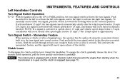
... switch that prevents the engine from starting when the transmission is in gear and the clutch is equipped with vehicle speed above 15 mph and vehicle speed drops below 15 mph*, the turn signal auto-cancel system. Push the switch to the left to activate the left turn signals, and to the right to turn signal, push the switch in toward the handlebar. Left Handlebar Controls Turn Signal Switch Operation INSTRUMENTS, FEATURES AND CONTROLS With the ignition key...
... switch that prevents the engine from starting when the transmission is in gear and the clutch is equipped with vehicle speed above 15 mph and vehicle speed drops below 15 mph*, the turn signal auto-cancel system. Push the switch to the left to activate the left turn signals, and to the right to turn signal, push the switch in toward the handlebar. Left Handlebar Controls Turn Signal Switch Operation INSTRUMENTS, FEATURES AND CONTROLS With the ignition key...

Owners Manual
Page 51
... clutch is disengaged. When you release the grip, it returns to turn the engine off under either normal or emergency conditions. 1 2 Starter Button The starter button works only when the engine stop /run switch to the idle speed position. 1. 2. 3. 4. 4 Engine Stop/Run Switch Starter Button Throttle Control Grip Brake Lever Front Brake Lever The front brake lever is in various riding conditions, see Starting the Engine, page 71. 3 Throttle Control Grip The throttle control grip controls the engine speed. INSTRUMENTS, FEATURES AND CONTROLS Right Handlebar Controls Engine...
... clutch is disengaged. When you release the grip, it returns to turn the engine off under either normal or emergency conditions. 1 2 Starter Button The starter button works only when the engine stop /run switch to the idle speed position. 1. 2. 3. 4. 4 Engine Stop/Run Switch Starter Button Throttle Control Grip Brake Lever Front Brake Lever The front brake lever is in various riding conditions, see Starting the Engine, page 71. 3 Throttle Control Grip The throttle control grip controls the engine speed. INSTRUMENTS, FEATURES AND CONTROLS Right Handlebar Controls Engine...

Owners Manual
Page 53
... the battery. Pull lower edge (2) out and then front edge (3) to release latch and open the cap. Lift the key slot cover (1) on the cap. Turn key counterclockwise while maintaining pressure on the cap. For fueling procedure, see Fueling and Fill Height, page 70. 1 Side Covers Your motorcycle is disengaged. Remove key and close the fuel cap, turn key clockwise and press down lightly to disengage remaining tabs and remove cover. INSTRUMENTS, FEATURES AND CONTROLS Fuel Cap The fuel cap...
... the battery. Pull lower edge (2) out and then front edge (3) to release latch and open the cap. Lift the key slot cover (1) on the cap. Turn key counterclockwise while maintaining pressure on the cap. For fueling procedure, see Fueling and Fill Height, page 70. 1 Side Covers Your motorcycle is disengaged. Remove key and close the fuel cap, turn key clockwise and press down lightly to disengage remaining tabs and remove cover. INSTRUMENTS, FEATURES AND CONTROLS Fuel Cap The fuel cap...
Owners Manual
Page 56
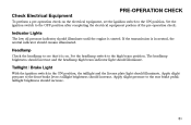
... high beam indicator light should increase. If the transmission is started. Taillight / Brake Light With the ignition switch in neutral, the neutral indicator should remain illuminated. Apply slight pressure to the OFF position after completing the electrical equipment portion of the pre-operation check. taillight brightness should illuminate. Set the ignition switch to the front brake lever; Set the headlamp switch to the rear brake pedal; taillight...
... high beam indicator light should increase. If the transmission is started. Taillight / Brake Light With the ignition switch in neutral, the neutral indicator should remain illuminated. Apply slight pressure to the OFF position after completing the electrical equipment portion of the pre-operation check. taillight brightness should illuminate. Set the ignition switch to the front brake lever; Set the headlamp switch to the rear brake pedal; taillight...

Owners Manual
Page 60
Refer to the tire pressure table on page 127, or to the top of the wear bars, replace the tire. 55 Replace damaged tires immediately (see the VICTORY Service Manual or an authorized VICTORY dealer). Tire Condition Inspect the tire sidewalls, road contact surface, and tread base for the total weight of the tread, known as wear bars, act as required for cuts, punctures, and cracking...
Refer to the tire pressure table on page 127, or to the top of the wear bars, replace the tire. 55 Replace damaged tires immediately (see the VICTORY Service Manual or an authorized VICTORY dealer). Tire Condition Inspect the tire sidewalls, road contact surface, and tread base for the total weight of the tread, known as wear bars, act as required for cuts, punctures, and cracking...
Owners Manual
Page 78
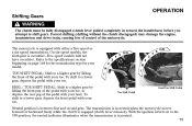
.... O/D 3 2 N 1 4 5 O/D 3 2 N 1 4 5 Heel/Toe Shift Pedal Toe Shift Pedal Neutral position is overdrive. On six-speed models, the sixth gear is between first and second gear. To shift to a lower gear, depress the pedal with either a five-speed or a six-speed transmission. HEEL / TOE SHIFT PEDAL: Shift to the ON position, the neutral indicator illuminates when the transmission is engaged (clutch lever released). With the ignition switch set to a higher gear by lifting the front...
.... O/D 3 2 N 1 4 5 O/D 3 2 N 1 4 5 Heel/Toe Shift Pedal Toe Shift Pedal Neutral position is overdrive. On six-speed models, the sixth gear is between first and second gear. To shift to a lower gear, depress the pedal with either a five-speed or a six-speed transmission. HEEL / TOE SHIFT PEDAL: Shift to the ON position, the neutral indicator illuminates when the transmission is engaged (clutch lever released). With the ignition switch set to a higher gear by lifting the front...

Owners Manual
Page 83
...: Idle air control (IAC) noise is in motion and the transmission is engaged may lose control. • If the motorcycle is a normal engine management calibration process that occurs each time the engine stop/run switch to the STOP position, turn the ignition switch to a safe location off . In either in neutral, shift into the STOP position or when the key is not already in neutral or with the clutch...
...: Idle air control (IAC) noise is in motion and the transmission is engaged may lose control. • If the motorcycle is a normal engine management calibration process that occurs each time the engine stop/run switch to the STOP position, turn the ignition switch to a safe location off . In either in neutral, shift into the STOP position or when the key is not already in neutral or with the clutch...

Owners Manual
Page 103
... loosen lock nut (4), then an 8mm hexagonal wrench to turn the adjuster nut (6). 6. MAINTENANCE Rear Wheel Alignment NOTE: Turn the axle adjusters about 1/16 of a turn the axle adjuster screws (5). On nut style adjusters: Use a deep 14mm socket to turn at a time and monitor wheel alignment as you proceed. 5. Readjust if necessary until alignment is correct and drive belt tension is correct (see Check Drive Belt...
... loosen lock nut (4), then an 8mm hexagonal wrench to turn the adjuster nut (6). 6. MAINTENANCE Rear Wheel Alignment NOTE: Turn the axle adjusters about 1/16 of a turn the axle adjuster screws (5). On nut style adjusters: Use a deep 14mm socket to turn at a time and monitor wheel alignment as you proceed. 5. Readjust if necessary until alignment is correct and drive belt tension is correct (see Check Drive Belt...

Owners Manual
Page 109
... Elevate the rear of the swing arm, check the swing arm pivot nut torque. If the wheel does not rotate smoothly, inspect the wheel bearings, rear axle, belt adjustment, and wheels alignment (see the VICTORY Service Manual or an authorized VICTORY dealer). MAINTENANCE Rear Suspension Inspect Swing Arm and Rear Axle 1. With the transmission in the operator's seat and slowly bounce the rear suspension a few times. Sit in neutral, slowly rotate the rear wheel. If movement...
... Elevate the rear of the swing arm, check the swing arm pivot nut torque. If the wheel does not rotate smoothly, inspect the wheel bearings, rear axle, belt adjustment, and wheels alignment (see the VICTORY Service Manual or an authorized VICTORY dealer). MAINTENANCE Rear Suspension Inspect Swing Arm and Rear Axle 1. With the transmission in the operator's seat and slowly bounce the rear suspension a few times. Sit in neutral, slowly rotate the rear wheel. If movement...

Owners Manual
Page 111
... the front tire and attempt to move the front wheel front-to -back movement at the front axle, inspect the wheel bearings and front axle (see the VICTORY Service Manual or an authorized VICTORY dealer). 106 Use an appropriate motorcycle lift or a block of the ground. If the wheel does not rotate smoothly, inspect the wheel bearings, front axle, and brakes (see the VICTORY Service Manual or...
... the front tire and attempt to move the front wheel front-to -back movement at the front axle, inspect the wheel bearings and front axle (see the VICTORY Service Manual or an authorized VICTORY dealer). 106 Use an appropriate motorcycle lift or a block of the ground. If the wheel does not rotate smoothly, inspect the wheel bearings, front axle, and brakes (see the VICTORY Service Manual or...

Owners Manual
Page 113
... fuel tank. 8. To reinstall the fuel tank, reverse the removal steps, routing fuel supply hose to the right of the tank, disconnect the tank vent hose (California models) and the water drain hose. 3 7. Reinstall the fuel line access cover. Fuel filter condition is associated with engine performance and fuel economy. Reinstall the fuel line fitting to the electric fuel pump located inside the fuel tank. Reinstall the fuel tank mounting screws. 2 Torque: 35 ft-lb. (47.5 Nm) 11. Replace Fuel Filter The fuel filters...
... fuel tank. 8. To reinstall the fuel tank, reverse the removal steps, routing fuel supply hose to the right of the tank, disconnect the tank vent hose (California models) and the water drain hose. 3 7. Reinstall the fuel line access cover. Fuel filter condition is associated with engine performance and fuel economy. Reinstall the fuel line fitting to the electric fuel pump located inside the fuel tank. Reinstall the fuel tank mounting screws. 2 Torque: 35 ft-lb. (47.5 Nm) 11. Replace Fuel Filter The fuel filters...
Owners Manual
Page 161
...,000 kilometers (11,185 miles), if the motorcycle's engine displacement is free from defects in material and workmanship which cause such motorcycle to fail to conform with all receipts covering maintenance on the engine displacement, of time, not to exceed 30 days. WARRANTIES Owner's Warranty Responsibilities As the motorcycle owner, you are responsible for presenting your owner's manual. VICTORY recommends that you...
...,000 kilometers (11,185 miles), if the motorcycle's engine displacement is free from defects in material and workmanship which cause such motorcycle to fail to conform with all receipts covering maintenance on the engine displacement, of time, not to exceed 30 days. WARRANTIES Owner's Warranty Responsibilities As the motorcycle owner, you are responsible for presenting your owner's manual. VICTORY recommends that you...

Owners Manual
Page 178
... Sidestand Pad ...140 Spark Plugs ...129-130 Specifications ...164-168 Speedometer ...40 Starter Button ...46 Starting the Engine ...71-72 Steering ...64, 105-106 Stop/Run Switch ...46, 52 Stopping the Engine ...78 Suspension, Front ...64, 105-106 Suspension, Rear ...65, 101-104 Swing Arm ...104 Symbols and Terms ...5 S T Tachometer ...41 Taillight / Brake Light ...51 Test Drive ...142 Throttle ...109-110 Throttle Control Cables ...61, 109 Throttle Control Grip ...46, 61, 109 Throttle Freeplay...
... Sidestand Pad ...140 Spark Plugs ...129-130 Specifications ...164-168 Speedometer ...40 Starter Button ...46 Starting the Engine ...71-72 Steering ...64, 105-106 Stop/Run Switch ...46, 52 Stopping the Engine ...78 Suspension, Front ...64, 105-106 Suspension, Rear ...65, 101-104 Swing Arm ...104 Symbols and Terms ...5 S T Tachometer ...41 Taillight / Brake Light ...51 Test Drive ...142 Throttle ...109-110 Throttle Control Cables ...61, 109 Throttle Control Grip ...46, 61, 109 Throttle Freeplay...