
Owners Manual
Page 29
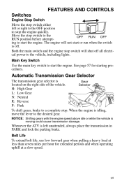
... vehicle is off all electrical power to a complete stop. FEATURES AND CONTROLS Switches Engine Stop Switch Move the stop switch either left unattended, always place the transmission in PARK and lock the parking brake. Both the main switch and the engine stop switch will not start the engine. See page 57 for extended periods and when operating uphill at a slow speed. 25 Selector H: High Gear L: Low Gear N: Neutral R: Reverse P: Park To shift gears, brake to the vehicle, including lights...
... vehicle is off all electrical power to a complete stop. FEATURES AND CONTROLS Switches Engine Stop Switch Move the stop switch either left unattended, always place the transmission in PARK and lock the parking brake. Both the main switch and the engine stop switch will not start the engine. See page 57 for extended periods and when operating uphill at a slow speed. 25 Selector H: High Gear L: Low Gear N: Neutral R: Reverse P: Park To shift gears, brake to the vehicle, including lights...
Owners Manual
Page 37
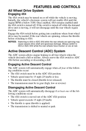
... throttle must be closed (throttle lever released) • The transmission must be in gear (high, low or reverse) Disengaging Active Descent Control The ADC system will automatically disengage if at rest. FEATURES AND CONTROLS All Wheel Drive System Engaging 4X4 The 4X4 switch may be turned on or off while the vehicle is moving , it will not disengage until the rear wheels regain traction. Initially, the vehicle...
... throttle must be closed (throttle lever released) • The transmission must be in gear (high, low or reverse) Disengaging Active Descent Control The ADC system will automatically disengage if at rest. FEATURES AND CONTROLS All Wheel Drive System Engaging 4X4 The 4X4 switch may be turned on or off while the vehicle is moving , it will not disengage until the rear wheels regain traction. Initially, the vehicle...
Owners Manual
Page 39
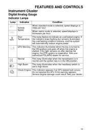
... the transmission is in neutral and the ignition key is selected, speed displays in kilometers per hour. Check Engine This indicator appears if an EFI-related fault occurs. If the indicator stops flashing but remains illuminated, the overheating condition remains, and the system will automatically reduce engine power. See your authorized POLARIS dealer for service. This lamp flashes to high beam. EPS Warning This...
... the transmission is in neutral and the ignition key is selected, speed displays in kilometers per hour. Check Engine This indicator appears if an EFI-related fault occurs. If the indicator stops flashing but remains illuminated, the overheating condition remains, and the system will automatically reduce engine power. See your authorized POLARIS dealer for service. This lamp flashes to high beam. EPS Warning This...

Owners Manual
Page 41
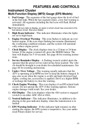
... fuel sensor circuit. H = High Gear L = Low Gear N = Neutral R = Reverse Gear P = Park -- = Gear Signal Error (or shifter between gears) 2. See your dealer for 5-10 seconds. See page 33. 5. The clock displays time in the fuel tank. The time will flash. See page 39 for resetting instructions. 6. All segments including the fuel icon will display for scheduled maintenance. Clock Display - This area displays odometer, trip meter, engine hour meter, engine speed...
... fuel sensor circuit. H = High Gear L = Low Gear N = Neutral R = Reverse Gear P = Park -- = Gear Signal Error (or shifter between gears) 2. See your dealer for 5-10 seconds. See page 33. 5. The clock displays time in the fuel tank. The time will flash. See page 39 for resetting instructions. 6. All segments including the fuel icon will display for scheduled maintenance. Clock Display - This area displays odometer, trip meter, engine hour meter, engine speed...
Owners Manual
Page 47
... the transmission is in the fuel sensor circuit. See your dealer for scheduled maintenance. Fuel Gauge - Drive at idle and high electrical load (lights, cooling fan, accessories) is inoperative. See your dealer. 5. The time will flash. This warning usually indicates that the preset service interval has been reached. Serious engine damage could result. This icon displays when the 4X4 system is engaged (switch is on after starting the engine, the EPS system...
... the transmission is in the fuel sensor circuit. See your dealer for scheduled maintenance. Fuel Gauge - Drive at idle and high electrical load (lights, cooling fan, accessories) is inoperative. See your dealer. 5. The time will flash. This warning usually indicates that the preset service interval has been reached. Serious engine damage could result. This icon displays when the 4X4 system is engaged (switch is on after starting the engine, the EPS system...

Owners Manual
Page 53
... Code Definitions SPORTSMAN 550/550 EPS Diagnostic Codes Component Idle Air Control Starter Enable Circuit All Wheel Drive Control System Power Throttle Safety Signal Condition Driver Circuit Grounded Shorted Load* Driver Circuit Short to B+ Driver Circuit Short to B+ Voltage Too High Voltage Too low Voltage Too High Voltage Too Low Signal Out of Range Throttle Stuck Driver Circuit Short to B+ EPS Models Only Current Above Normal or Grounded Steering Excessive Current Error Current Above Normal or Grounded Steering Torque Sensor...
... Code Definitions SPORTSMAN 550/550 EPS Diagnostic Codes Component Idle Air Control Starter Enable Circuit All Wheel Drive Control System Power Throttle Safety Signal Condition Driver Circuit Grounded Shorted Load* Driver Circuit Short to B+ Driver Circuit Short to B+ Voltage Too High Voltage Too low Voltage Too High Voltage Too Low Signal Out of Range Throttle Stuck Driver Circuit Short to B+ EPS Models Only Current Above Normal or Grounded Steering Excessive Current Error Current Above Normal or Grounded Steering Torque Sensor...

Owners Manual
Page 54
... 523 523 651 651 651 652 652 652 1268 1269 1347 1347 1347 1071 1071 1071 634 634 634 634 1321 1321 1321 FMI 3 4 3 4 16 0 3 4 3 4 2 8 2 8 2 4 3 2 5 3 4 5 3 4 3 3 5 3 4 5 3 4 5 3 4 7 5 3 4 Intake Air Temperature Sensor Manifold Absolute Pressure Sensor Crankshaft Position Sensor Vehicle Speed Signal Gear Sensor Signal Injector 1 (MAG) (SDI Part Load) Injector 2 (PTO) (SDI Part Load) Ignition Coil Primary Driver 1 (MAG) Ignition Coil Primary Driver 2 (PTO) Fuel Pump Driver Circuit Fan Relay Driver Circuit Idle Air Control Starter Enable Circuit 50
... 523 523 651 651 651 652 652 652 1268 1269 1347 1347 1347 1071 1071 1071 634 634 634 634 1321 1321 1321 FMI 3 4 3 4 16 0 3 4 3 4 2 8 2 8 2 4 3 2 5 3 4 5 3 4 3 3 5 3 4 5 3 4 5 3 4 7 5 3 4 Intake Air Temperature Sensor Manifold Absolute Pressure Sensor Crankshaft Position Sensor Vehicle Speed Signal Gear Sensor Signal Injector 1 (MAG) (SDI Part Load) Injector 2 (PTO) (SDI Part Load) Ignition Coil Primary Driver 1 (MAG) Ignition Coil Primary Driver 2 (PTO) Fuel Pump Driver Circuit Fan Relay Driver Circuit Idle Air Control Starter Enable Circuit 50

Owners Manual
Page 55
FEATURES AND CONTROLS Instrument Cluster Diagnostic Display Code Definitions SPORTSMAN 850 XP/850 XP EPS Diagnostic Codes Component Chassis Relay Condition Driver Circuit Open/Grounded Driver Circuit Short to B+ Driver Circuit Grounded Driver Circuit Open/Grounded Driver Circuit Short to B+ Driver Circuit Grounded Voltage Too High Voltage Too low Voltage Too High Voltage Too Low Signal Out of Range Throttle Stuck Driver Circuit Open/Grounded Driver Circuit Short to B+ Driver Circuit Grounded Speed Too High Speed Too Low EPS Models Only Steering Over Current Shutdown Steering Excessive...
FEATURES AND CONTROLS Instrument Cluster Diagnostic Display Code Definitions SPORTSMAN 850 XP/850 XP EPS Diagnostic Codes Component Chassis Relay Condition Driver Circuit Open/Grounded Driver Circuit Short to B+ Driver Circuit Grounded Driver Circuit Open/Grounded Driver Circuit Short to B+ Driver Circuit Grounded Voltage Too High Voltage Too low Voltage Too High Voltage Too Low Signal Out of Range Throttle Stuck Driver Circuit Open/Grounded Driver Circuit Short to B+ Driver Circuit Grounded Speed Too High Speed Too Low EPS Models Only Steering Over Current Shutdown Steering Excessive...

Owners Manual
Page 57
... full throttle or high speeds during the break-in of a new engine and drive components will damage close-fitted engine parts and drive components. Add oil if necessary to familiarize yourself with gasoline. Change both the oil and the filter at first. Read and understand all safety warnings outlined in 1. See page 31. Pull only light loads. 7. Fill the fuel tank with vehicle operation and handling. 4. Avoid...
... full throttle or high speeds during the break-in of a new engine and drive components will damage close-fitted engine parts and drive components. Add oil if necessary to familiarize yourself with gasoline. Change both the oil and the filter at first. Read and understand all safety warnings outlined in 1. See page 31. Pull only light loads. 7. Fill the fuel tank with vehicle operation and handling. 4. Avoid...

Owners Manual
Page 73
... warning labels and in serious damage to maintain stable driving conditions. Use low forward gear when hauling or towing heavy cargo to extend belt life. 1/3 Towing Loads Always attach a towed load to the hitch point. Always install POLARIS-approved (or equivalent) accessories designed for your POLARIS ATV. Cargo weight should be evenly distributed (1/3 on the front rack and 2/ 3 on hitch) must not exceed the maximum weight capacity of rear rack...
... warning labels and in serious damage to maintain stable driving conditions. Use low forward gear when hauling or towing heavy cargo to extend belt life. 1/3 Towing Loads Always attach a towed load to the hitch point. Always install POLARIS-approved (or equivalent) accessories designed for your POLARIS ATV. Cargo weight should be evenly distributed (1/3 on the front rack and 2/ 3 on hitch) must not exceed the maximum weight capacity of rear rack...

Owners Manual
Page 79
... leaks at tank cap, lines, filter, pump; MAINTENANCE Periodic Maintenance Chart Item Maintenance Interval (whichever comes first) Hours Fuel system X Engine mounts Exhaust muffler/ pipe nE Spark plug Remarks Calendar 12 M Miles (Km) 1000 (1600) Check for wear, routing, security; replace as needed 100 H 100 H 100 H 100 H 100 H 12 M 12 M 12 M 12 M X Wiring n Clutches (drive 100 H 100 H 200 H 200 H 300 H 1000 H 12 M 12 M 24 M 24 M 36 M - and driven) n Front wheel bearings n Brake fluid X ADC fluid n Spark...
... leaks at tank cap, lines, filter, pump; MAINTENANCE Periodic Maintenance Chart Item Maintenance Interval (whichever comes first) Hours Fuel system X Engine mounts Exhaust muffler/ pipe nE Spark plug Remarks Calendar 12 M Miles (Km) 1000 (1600) Check for wear, routing, security; replace as needed 100 H 100 H 100 H 100 H 100 H 12 M 12 M 12 M 12 M X Wiring n Clutches (drive 100 H 100 H 200 H 200 H 300 H 1000 H 12 M 12 M 24 M 24 M 36 M - and driven) n Front wheel bearings n Brake fluid X ADC fluid n Spark...

Owners Manual
Page 101
... MAINTENANCE Lights Poor lighting can cause burns to skin. Always make sure lights are adjusted properly for best visibility. Remove the five (5) headlight pod screws. 2. Allow lamps to remove it with bare fingers. Turn the lamp counterclockwise to cool before servicing. 3. Headlight Lamp Replacement When servicing a halogen lamp, avoid touching the lamp with denatured alcohol. 1. Lift the pod cover and disconnect the speedometer harnesses...
... MAINTENANCE Lights Poor lighting can cause burns to skin. Always make sure lights are adjusted properly for best visibility. Remove the five (5) headlight pod screws. 2. Allow lamps to remove it with bare fingers. Turn the lamp counterclockwise to cool before servicing. 3. Headlight Lamp Replacement When servicing a halogen lamp, avoid touching the lamp with denatured alcohol. 1. Lift the pod cover and disconnect the speedometer harnesses...

Owners Manual
Page 102
... the headlamp to the center of the headlight beam should be adjusted slightly upward or downward. Use the following procedure to high beam. 4. Turn the headlight switch to make a mark on a level surface with the headlight approximately 25 ft. (7.6 m) from the floor to the desired position, then tighten the screw. 98 Start the engine. Position the vehicle on the wall...
... the headlamp to the center of the headlight beam should be adjusted slightly upward or downward. Use the following procedure to high beam. 4. Turn the headlight switch to make a mark on a level surface with the headlight approximately 25 ft. (7.6 m) from the floor to the desired position, then tighten the screw. 98 Start the engine. Position the vehicle on the wall...

Owners Manual
Page 104
Unplug the headlamp from the speedometer. 3. Reverse the steps to remove the o-rings from the locking tabs. 6. Use a small screwdriver to install the new housing and reassemble the pod. 100 Remove the five (5) headlight pod screws. 2. Carefully pull the assembly up to release it from the headlight mounting tabs. 5. Lift the pod cover and disconnect the speedometer harnesses from the wiring harness. 4. Pull the headlight housing up and out of the pod. 7. MAINTENANCE Lights Headlight Housing Replacement 1.
Unplug the headlamp from the speedometer. 3. Reverse the steps to remove the o-rings from the locking tabs. 6. Use a small screwdriver to install the new housing and reassemble the pod. 100 Remove the five (5) headlight pod screws. 2. Carefully pull the assembly up to release it from the headlight mounting tabs. 5. Lift the pod cover and disconnect the speedometer harnesses from the wiring harness. 4. Pull the headlight housing up and out of the pod. 7. MAINTENANCE Lights Headlight Housing Replacement 1.

Owners Manual
Page 105
... headlamp. 1. Reinstall the harness connector. 5. Test the light for proper operation. Install the new lamp. 4. MAINTENANCE Lights Lower Headlamp Replacement 1. Turn the back of the headlight harness counterclockwise and pull the harness assembly away from the back of the light assembly. 2. Harness Taillight/Brakelight Lamp Replacement Taillight 101 Remove the headlamp and install the new headlamp. 3. Reinstall the harness assembly into the headlight assembly. 4. Remove the harness connector from the headlight assembly. 2.
... headlamp. 1. Reinstall the harness connector. 5. Test the light for proper operation. Install the new lamp. 4. MAINTENANCE Lights Lower Headlamp Replacement 1. Turn the back of the headlight harness counterclockwise and pull the harness assembly away from the back of the light assembly. 2. Harness Taillight/Brakelight Lamp Replacement Taillight 101 Remove the headlamp and install the new headlamp. 3. Reinstall the harness assembly into the headlight assembly. 4. Remove the harness connector from the headlight assembly. 2.
Owners Manual
Page 122
...; Transmission • Brake fluid (change every two years and any necessary repairs and then clean the vehicle as recommended. Oil and Filter Change the oil and filter. Add POLARIS Carbon Clean Fuel Treatment or POLARIS Fuel Stabilizer. See page 78. Fill the fuel tank. 2. Fluid Levels Inspect the following fluid levels. See page 116. Carbon Clean removes water from fuel systems, stabilizes fuel and removes carbon deposits from pistons, rings, valves and exhaust systems. 3. Change fluids...
...; Transmission • Brake fluid (change every two years and any necessary repairs and then clean the vehicle as recommended. Oil and Filter Change the oil and filter. Add POLARIS Carbon Clean Fuel Treatment or POLARIS Fuel Stabilizer. See page 78. Fill the fuel tank. 2. Fluid Levels Inspect the following fluid levels. See page 116. Carbon Clean removes water from fuel systems, stabilizes fuel and removes carbon deposits from pistons, rings, valves and exhaust systems. 3. Change fluids...

Owners Manual
Page 130
...) (EPS) Fuel Capacity 5.25 gal. (20 l) Engine Oil Capacity 2 qts. (1.9 l) Coolant Capacity 2 qts. (1.9 l) Rear Gearcase Oil Capacity 7.1 oz. (210 ml) Demand Drive Fluid Capacity 9.3 oz. (275 ml) Transmission Oil Capacity 32 oz. (950 ml) Front Rack/Storage Box Capacity 120 lbs. (54 kg) Rear Rack Capacity 240 lbs. (109 kg) Receiver Hitch Tongue Capacity 150 lbs. (68 kg) (Rear rack load and tongue weight not to exceed 240 lbs. /109 kg) Hitch Towing Rating 1500 lbs. (680.4 kg) Unbraked Trailer Towing 1786...
...) (EPS) Fuel Capacity 5.25 gal. (20 l) Engine Oil Capacity 2 qts. (1.9 l) Coolant Capacity 2 qts. (1.9 l) Rear Gearcase Oil Capacity 7.1 oz. (210 ml) Demand Drive Fluid Capacity 9.3 oz. (275 ml) Transmission Oil Capacity 32 oz. (950 ml) Front Rack/Storage Box Capacity 120 lbs. (54 kg) Rear Rack Capacity 240 lbs. (109 kg) Receiver Hitch Tongue Capacity 150 lbs. (68 kg) (Rear rack load and tongue weight not to exceed 240 lbs. /109 kg) Hitch Towing Rating 1500 lbs. (680.4 kg) Unbraked Trailer Towing 1786...

Owners Manual
Page 132
SPECIFICATIONS SPORTSMAN 850 XP / 850 XP EPS Maximum Weight Capacity Dry Weight 575 lbs. (261 kg) 759 lbs. (344.3 kg) (XP) 767 lbs. (347.9 kg) (XP EPS) Fuel Capacity 5.25 gal. (20 l) Engine Oil Capacity 2 qts. (1.9 l) Coolant Capacity 2 qts. (1.9 l) Rear Gearcase Oil Capacity 7.1 oz. (210 ml) Demand Drive Fluid Capacity 9.3 oz. (275 ml) Transmission Oil Capacity 32 oz. (950 ml) Front Rack/Storage Box Capacity 120 lbs. (54 kg) Rear Rack Capacity 240 lbs. (109 kg) Receiver Hitch Tongue Capacity 150 lbs. (68 kg) (Rear rack load and tongue...
SPECIFICATIONS SPORTSMAN 850 XP / 850 XP EPS Maximum Weight Capacity Dry Weight 575 lbs. (261 kg) 759 lbs. (344.3 kg) (XP) 767 lbs. (347.9 kg) (XP EPS) Fuel Capacity 5.25 gal. (20 l) Engine Oil Capacity 2 qts. (1.9 l) Coolant Capacity 2 qts. (1.9 l) Rear Gearcase Oil Capacity 7.1 oz. (210 ml) Demand Drive Fluid Capacity 9.3 oz. (275 ml) Transmission Oil Capacity 32 oz. (950 ml) Front Rack/Storage Box Capacity 120 lbs. (54 kg) Rear Rack Capacity 240 lbs. (109 kg) Receiver Hitch Tongue Capacity 150 lbs. (68 kg) (Rear rack load and tongue...

Owners Manual
Page 141
... defects in addition to the POLARIS standard limited warranty for evaporative emissions Fuel Tank Fuel Cap Fuel Line Fuel Line Fittings Clamps* Pressure Relief Valves* Control Valves* Control Solenoids* Electronic Controls Vacuum Control Diaphragms* Control Cables* Control Linkages* Purge Valves Vapor Hoses Liquid/Vapor Separator Carbon Canister Canister Mounting Brackets Carburetor Purge Port Connector *As related to meet these regulations. This emissions limited warranty covers components whose failure increases the vehicle's regulated emissions, and it conforms...
... defects in addition to the POLARIS standard limited warranty for evaporative emissions Fuel Tank Fuel Cap Fuel Line Fuel Line Fittings Clamps* Pressure Relief Valves* Control Valves* Control Solenoids* Electronic Controls Vacuum Control Diaphragms* Control Cables* Control Linkages* Purge Valves Vapor Hoses Liquid/Vapor Separator Carbon Canister Canister Mounting Brackets Carburetor Purge Port Connector *As related to meet these regulations. This emissions limited warranty covers components whose failure increases the vehicle's regulated emissions, and it conforms...

Owners Manual
Page 148
...No Passenger" Warning...22 Age 16 Warning...21 Clutch Cover Warning...23 Discretionary Warning...21 General Warning ...20 Hitch Capacity Label ...23 Rack Warning, Front and Rear 23 Reverse Override Warning ...21 Tire Pressure/Load Warning . . 22 Safety Training ...7 Safety Warnings...10-19 Severe Use ...72 Side Panel Removal...91 Sidehilling ...62 Signal Words ...4 Spark Arrestor ...105 Spark Plug Inspection ...102-103 Spark Plug Recommendations...102 Spark Plugs ...102-103 Speedometer ...34 Spring Adjustment, Shock ...109 Starting the Engine ...57 V Vehicle Identification Numbers...6 Vehicle...
...No Passenger" Warning...22 Age 16 Warning...21 Clutch Cover Warning...23 Discretionary Warning...21 General Warning ...20 Hitch Capacity Label ...23 Rack Warning, Front and Rear 23 Reverse Override Warning ...21 Tire Pressure/Load Warning . . 22 Safety Training ...7 Safety Warnings...10-19 Severe Use ...72 Side Panel Removal...91 Sidehilling ...62 Signal Words ...4 Spark Arrestor ...105 Spark Plug Inspection ...102-103 Spark Plug Recommendations...102 Spark Plugs ...102-103 Speedometer ...34 Spring Adjustment, Shock ...109 Starting the Engine ...57 V Vehicle Identification Numbers...6 Vehicle...