

Owners Manual
Page 12
...in mind: 1. Since Yamaha cannot test all other accessories that would impair the performance of your motorcycle. Carefully inspect the accessory before riding. Check accessory mounts and cargo restraints frequently. 3. Accessories Genuine Yamaha accessories have been specifically designed for the proper... front fender. These items, including such cargo as sleeping bags, duffel bags, or tents, can create a sudden imbalance. Shifting weights can create unstable handling or slow steering response. SAFETY INFORMATION Loading The total weight of the operator, passenger, accessories and ...
...in mind: 1. Since Yamaha cannot test all other accessories that would impair the performance of your motorcycle. Carefully inspect the accessory before riding. Check accessory mounts and cargo restraints frequently. 3. Accessories Genuine Yamaha accessories have been specifically designed for the proper... front fender. These items, including such cargo as sleeping bags, duffel bags, or tents, can create a sudden imbalance. Shifting weights can create unstable handling or slow steering response. SAFETY INFORMATION Loading The total weight of the operator, passenger, accessories and ...

Owners Manual
Page 13
... your motorcycle in a closed area. When parking the motorcycle, note the following: 1-5 If accessories are not recommended. 2. c. 2. GASOLINE IS HIGHLY FLAMMABLE: Always turn the engine off when refueling. a. Accessories fitted to improper weight distribution or aerodynamic changes. This improper position limits the freedom of movement of lights or engine power. 1 Gasoline and exhaust gas 1. SAFETY INFORMATION a. Certain accessories can create instability due to the...
... your motorcycle in a closed area. When parking the motorcycle, note the following: 1-5 If accessories are not recommended. 2. c. 2. GASOLINE IS HIGHLY FLAMMABLE: Always turn the engine off when refueling. a. Accessories fitted to improper weight distribution or aerodynamic changes. This improper position limits the freedom of movement of lights or engine power. 1 Gasoline and exhaust gas 1. SAFETY INFORMATION a. Certain accessories can create instability due to the...

Owners Manual
Page 24
INSTRUMENT AND CONTROL FUNCTIONS Main switch/steering lock ...3-1 Indicator and warning lights ...3-2 Speedometer unit ...3-2 Handlebar switches ...3-3 Clutch lever ...3-4 Shift pedal (XVS650)...3-4 Shift pedal (XVS650A) ...3-4 Brake lever ...3-5 Brake pedal ...3-5 Fuel tank cap ...3-6 Fuel ...3-7 Fuel cock ...3-8 Starter (choke) knob...3-9 Seats (XVS650) ...3-9 Seats (XVS650A) ...3-11 Helmet holder ...3-12 Storage compartment ...3-13 Adjusting the shock absorber assembly ...3-14 Luggage strap holders ...3-15 Sidestand ...3-15 Ignition circuit cut-off system ...3-16 3
INSTRUMENT AND CONTROL FUNCTIONS Main switch/steering lock ...3-1 Indicator and warning lights ...3-2 Speedometer unit ...3-2 Handlebar switches ...3-3 Clutch lever ...3-4 Shift pedal (XVS650)...3-4 Shift pedal (XVS650A) ...3-4 Brake lever ...3-5 Brake pedal ...3-5 Fuel tank cap ...3-6 Fuel ...3-7 Fuel cock ...3-8 Starter (choke) knob...3-9 Seats (XVS650) ...3-9 Seats (XVS650A) ...3-11 Helmet holder ...3-12 Storage compartment ...3-13 Adjusting the shock absorber assembly ...3-14 Luggage strap holders ...3-15 Sidestand ...3-15 Ignition circuit cut-off system ...3-16 3
Owners Manual
Page 26
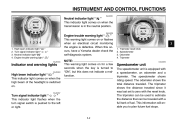
... beam indicator light " " Turn signal indicator light " " Neutral indicator light " " Engine trouble warning light " " EAU03034 Engine trouble warning light " " This warning light comes on or flashes when an electrical circuit monitoring the engine is equipped with a speedometer, an odometer and a tripmeter. NOTE: This warning light comes on for a few seconds when the key is switched on. This information will enable you to "ON", but this occurs, have a Yamaha dealer check the...
... beam indicator light " " Turn signal indicator light " " Neutral indicator light " " Engine trouble warning light " " EAU03034 Engine trouble warning light " " This warning light comes on or flashes when an electrical circuit monitoring the engine is equipped with a speedometer, an odometer and a tripmeter. NOTE: This warning light comes on for a few seconds when the key is switched on. This information will enable you to "ON", but this occurs, have a Yamaha dealer check the...
Owners Manual
Page 27
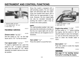
... switch " / 2. To signal a left-hand turn signal lights can also be canceled manually by pushing the switch in case of an emergency, such as when the motorcycle overturns or when the throttle cable is equipped with the starter. Set this switch to stop switch " 2. EC000005 CAUTION: See page 5-1 for starting the engine. @ @ 3-3 Horn switch " " Press this switch to " " for the low beam. EAU00143 Start switch " " Push this switch to starting...
... switch " / 2. To signal a left-hand turn signal lights can also be canceled manually by pushing the switch in case of an emergency, such as when the motorcycle overturns or when the throttle cable is equipped with the starter. Set this switch to stop switch " 2. EC000005 CAUTION: See page 5-1 for starting the engine. @ @ 3-3 Horn switch " " Press this switch to " " for the low beam. EAU00143 Start switch " " Push this switch to starting...
Owners Manual
Page 31
...: 3 L (0.7 Imp gal, 0.8 US gal) ECA00102 Your Yamaha engine has been designed to the fuel system or vehicle performance problems. _ WARNING ● Do not overfill the fuel tank, otherwise it can be used if the ethanol content does not exceed 10%. Gasohol There are two types of leaded gasoline will extend spark plug life and reduce maintenance costs. Gasohol containing ethanol can cause damage...
...: 3 L (0.7 Imp gal, 0.8 US gal) ECA00102 Your Yamaha engine has been designed to the fuel system or vehicle performance problems. _ WARNING ● Do not overfill the fuel tank, otherwise it can be used if the ethanol content does not exceed 10%. Gasohol There are two types of leaded gasoline will extend spark plug life and reduce maintenance costs. Gasohol containing ethanol can cause damage...

Owners Manual
Page 39
... damping performance. ● Always have a Yamaha dealer service the shock absorber. @ @ Sidestand The sidestand is a luggage strap holder on the left side of the ignition circuit cut -off system.) @ @ 1. The manufacturer cannot be held responsible for an explanation of the frame. INSTRUMENT AND CONTROL FUNCTIONS EAU00315 EAU00330 3 WARNING This shock absorber contains highly pressurized nitrogen gas. Raise the sidestand or lower it...
... damping performance. ● Always have a Yamaha dealer service the shock absorber. @ @ Sidestand The sidestand is a luggage strap holder on the left side of the ignition circuit cut -off system.) @ @ 1. The manufacturer cannot be held responsible for an explanation of the frame. INSTRUMENT AND CONTROL FUNCTIONS EAU00315 EAU00330 3 WARNING This shock absorber contains highly pressurized nitrogen gas. Raise the sidestand or lower it...

Owners Manual
Page 44
Check air pressure. Such an inspection can be made each time the motorcycle is defective, have it inspected and repaired before operating the motorcycle. @ @ 4-2 PRE-OPERATION CHECKS ITEM Control cables CHECKS • Make sure that all nuts, bolts and screws are properly ... • Check operation of ignition circuit cut-off system. • If system is used. Correct if necessary. PAGE 6-27 Wheels and tires 6-17-6-19 Brake and shift pedals Brake and clutch levers Sidestand Chassis fasteners Instruments, lights, signals and switches Sidestand switch • Make sure that ...
Check air pressure. Such an inspection can be made each time the motorcycle is defective, have it inspected and repaired before operating the motorcycle. @ @ 4-2 PRE-OPERATION CHECKS ITEM Control cables CHECKS • Make sure that all nuts, bolts and screws are properly ... • Check operation of ignition circuit cut-off system. • If system is used. Correct if necessary. PAGE 6-27 Wheels and tires 6-17-6-19 Brake and shift pedals Brake and clutch levers Sidestand Chassis fasteners Instruments, lights, signals and switches Sidestand switch • Make sure that ...

Owners Manual
Page 46
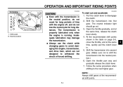
... the battery and its terminals, otherwise electrical failure and acid corrosion may result. Consult a Yamaha dealer regarding any length of consciousness and death within a short time. Exhaust fumes are poisonous, and inhaling them can cause loss of time. 5- Starting and warming up . OPERATION AND IMPORTANT RIDING POINTS EAU00373 EAU00376 EAU00372 EAU04219* @ 5 WARNING ● Become thoroughly familiar with all operating controls...
... the battery and its terminals, otherwise electrical failure and acid corrosion may result. Consult a Yamaha dealer regarding any length of consciousness and death within a short time. Exhaust fumes are poisonous, and inhaling them can cause loss of time. 5- Starting and warming up . OPERATION AND IMPORTANT RIDING POINTS EAU00373 EAU00376 EAU00372 EAU04219* @ 5 WARNING ● Become thoroughly familiar with all operating controls...
Owners Manual
Page 47
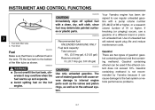
... the starter (choke) knob back halfway. Turn the fuel cock lever to "ON". 2. NOTE: When the transmission is in the neutral position, the neutral indicator light should come on or flashes after a few seconds, and then try again. Turn the key to "ON" and make sure that the engine stop the engine, and have a Yamaha dealer check the electrical circuit. _ _ _ 4. If the engine trouble warning light...
... the starter (choke) knob back halfway. Turn the fuel cock lever to "ON". 2. NOTE: When the transmission is in the neutral position, the neutral indicator light should come on or flashes after a few seconds, and then try again. Turn the key to "ON" and make sure that the engine stop the engine, and have a Yamaha dealer check the electrical circuit. _ _ _ 4. If the engine trouble warning light...
Owners Manual
Page 49
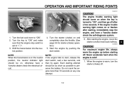
... changing gears to avoid damaging the engine, transmission, and drive train, which are not designed to shift the transmission into first gear. Open the throttle gradually, and at the recommended shift points. @ @ 5 5-4 Follow the same procedure when shifting to disengage the clutch. 2. Shift the transmission into the neutral position.) 6. Open the throttle part way and gradually release the clutch lever. 7. NOTE: Always shift gears at the same time, release the clutch lever slowly. 4. Shift...
... changing gears to avoid damaging the engine, transmission, and drive train, which are not designed to shift the transmission into first gear. Open the throttle gradually, and at the recommended shift points. @ @ 5 5-4 Follow the same procedure when shifting to disengage the clutch. 2. Shift the transmission into the neutral position.) 6. Open the throttle part way and gradually release the clutch lever. 7. NOTE: Always shift gears at the same time, release the clutch lever slowly. 4. Shift...
Owners Manual
Page 52
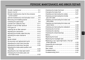
... MINOR REPAIR Periodic maintenance ...6-1 Owner's tool kit ...6-1 Periodic maintenance chart for the emission control system ...6-3 General maintenance and lubrication chart ...6-4 Removing and installing panels ...6-7 Checking the spark plugs ...6-9 Canister (for California only) ...6-11 Engine oil and oil filter element ...6-11 Final gear oil ...6-14 Cleaning the air filter element ...6-15 Adjusting the carburetors ...6-16 Adjusting the throttle cable free play ...6-17 Adjusting the valve clearance ...6-17 Tires ...6-17 Spoke wheels ...6-19 Accessories and replacement...
... MINOR REPAIR Periodic maintenance ...6-1 Owner's tool kit ...6-1 Periodic maintenance chart for the emission control system ...6-3 General maintenance and lubrication chart ...6-4 Removing and installing panels ...6-7 Checking the spark plugs ...6-9 Canister (for California only) ...6-11 Engine oil and oil filter element ...6-11 Final gear oil ...6-14 Cleaning the air filter element ...6-15 Adjusting the carburetors ...6-16 Adjusting the throttle cable free play ...6-17 Adjusting the valve clearance ...6-17 Tires ...6-17 Spoke wheels ...6-19 Accessories and replacement...
Owners Manual
Page 55
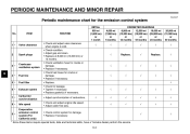
PERIODIC MAINTENANCE AND MINOR REPAIR EAU00471 Periodic maintenance chart for damage. • Replace if necessary. 2 Spark plugs √ Replace. √ Replace. √ 3 * Crankcase ventilation system √ √ √ √ √ 6 4 * 5 * 6 * 7 * 8 * Fuel line Fuel filter Exhaust system Carburetor synchronization Idle speed Evaporative emission control system (For California only) √ √ √ √ √ √ √ √ √ √ √ √ √ √ √ √ √ √ 9 * √...
PERIODIC MAINTENANCE AND MINOR REPAIR EAU00471 Periodic maintenance chart for damage. • Replace if necessary. 2 Spark plugs √ Replace. √ Replace. √ 3 * Crankcase ventilation system √ √ √ √ √ 6 4 * 5 * 6 * 7 * 8 * Fuel line Fuel filter Exhaust system Carburetor synchronization Idle speed Evaporative emission control system (For California only) √ √ √ √ √ √ √ √ √ √ √ √ √ √ √ √ √ √ 9 * √...

Owners Manual
Page 58
... air filter needs more frequent service if you are riding in unusually wet or dusty areas. ● Hydraulic brake service • Regularly check and, if necessary, correct the brake fluid level. • Every two years replace the internal components of the brake master cylinder and caliper, and change the brake fluid. • Replace the brake hoses every four years and if cracked or damaged. ● Engine oil type...
... air filter needs more frequent service if you are riding in unusually wet or dusty areas. ● Hydraulic brake service • Regularly check and, if necessary, correct the brake fluid level. • Every two years replace the internal components of the brake master cylinder and caliper, and change the brake fluid. • Replace the brake hoses every four years and if cracked or damaged. ● Engine oil type...

Owners Manual
Page 76
.... Brake pedal free play adjusting nut Brake pedal free play The brake pedal free play , turn the adjusting nut in direction a. To decrease the brake pedal free play should measure 20-30 mm (0.79-1.18 in direction b. 1. If necessary, adjust the brake light switch as follows. To make the brake light come on just before braking takes effect. PERIODIC MAINTENANCE AND MINOR REPAIR...
.... Brake pedal free play adjusting nut Brake pedal free play The brake pedal free play , turn the adjusting nut in direction a. To decrease the brake pedal free play should measure 20-30 mm (0.79-1.18 in direction b. 1. If necessary, adjust the brake light switch as follows. To make the brake light come on just before braking takes effect. PERIODIC MAINTENANCE AND MINOR REPAIR...

Owners Manual
Page 85
.... 2. Ignition fuse Signaling system fuse Headlight fuse Carburetor heater fuse Spare fuse (× 2) 3. Fuse box 2. If the fuse immediately blows again, have a Yamaha dealer check the electrical system. 30 A 15 A 10 A 10 A 15 A Specified fuses: Main fuse: Headlight fuse: Signaling system fuse: Ignition fuse: Carburetor heater fuse: 6-33 Turn the key to the electrical system and possibly a fire. _ _ 1. Spare main fuse EAU04190* Replacing the fuses 6 The main fuse and the fuse box, which contains the fuses for the individual circuits, are located behind panel...
.... 2. Ignition fuse Signaling system fuse Headlight fuse Carburetor heater fuse Spare fuse (× 2) 3. Fuse box 2. If the fuse immediately blows again, have a Yamaha dealer check the electrical system. 30 A 15 A 10 A 10 A 15 A Specified fuses: Main fuse: Headlight fuse: Signaling system fuse: Ignition fuse: Carburetor heater fuse: 6-33 Turn the key to the electrical system and possibly a fire. _ _ 1. Spare main fuse EAU04190* Replacing the fuses 6 The main fuse and the fuse box, which contains the fuses for the individual circuits, are located behind panel...

Owners Manual
Page 91
... torque: Brake torque rod bolt: 20 Nm (2.0 m·kgf, 14 ft·lb) 5. Tightening torque: Axle nut: 92 Nm (9.2 m·kgf, 67 ft·lb) 8. Middle gear universal joint 2. Install the rear wheel, wheel axle, final gear case, and drive shaft by pushing the wheel forward and guiding the drive shaft into the middle gear universal joint. 2. Install the panel. 6. Drive shaft EAU04191 6 6. Lift the rear wheel off the ground according to...
... torque: Brake torque rod bolt: 20 Nm (2.0 m·kgf, 14 ft·lb) 5. Tightening torque: Axle nut: 92 Nm (9.2 m·kgf, 67 ft·lb) 8. Middle gear universal joint 2. Install the rear wheel, wheel axle, final gear case, and drive shaft by pushing the wheel forward and guiding the drive shaft into the middle gear universal joint. 2. Install the panel. 6. Drive shaft EAU04191 6 6. Lift the rear wheel off the ground according to...

Owners Manual
Page 105
SPECIFICATIONS Bulb voltage, wattage × quantity Headlight Tail/brake light Front turn signal/ position light Rear turn signal light Meter lighting Neutral indicator light High beam indicator light Turn signal indicator light Engine trouble warning light Fuses Main fuse Ignition fuse Signaling system fuse Headlight fuse Carburetor heater fuse 30 A 10 A 10 A 15 A 15 A 12 V, 60/55 W × 1 12 V, 8/27 W × 1 12 V, 27/8 W × 2 12 V, 27 W × 2 12 V, 1.7 W × 1 12 V, 1.7 W × 1 12 V, 1.7 W × 1 12 V, 1.7 W × 1 12 V, 1.7 W × 1 8 8-5
SPECIFICATIONS Bulb voltage, wattage × quantity Headlight Tail/brake light Front turn signal/ position light Rear turn signal light Meter lighting Neutral indicator light High beam indicator light Turn signal indicator light Engine trouble warning light Fuses Main fuse Ignition fuse Signaling system fuse Headlight fuse Carburetor heater fuse 30 A 10 A 10 A 15 A 15 A 12 V, 60/55 W × 1 12 V, 8/27 W × 1 12 V, 27/8 W × 2 12 V, 27 W × 2 12 V, 1.7 W × 1 12 V, 1.7 W × 1 12 V, 1.7 W × 1 12 V, 1.7 W × 1 12 V, 1.7 W × 1 8 8-5

Owners Manual
Page 117
... Maintenance record ...9-5 Model label ...9-2 B Battery ...6-31 Brake and clutch levers, checking and lubricating ...6-28 Brake and shift pedals, checking and lubricating ...6-28 Brake fluid, changing ...6-27 Brake fluid level, checking...6-26 Brake lever...3-5 Brake lever free play, adjusting ...6-22 Brake light switch (rear), adjusting ...6-24 Brake pads and shoes, checking ...6-25 Brake pedal...3-5 Brake pedal position and free play, adjusting ...6-23 F Final gear oil...6-14 Front fork, checking ...6-29 Fuel ...3-7 Fuel cock...3-8 Fuel tank cap...3-6 Fuses, replacing ...6-33 N Neutral...
... Maintenance record ...9-5 Model label ...9-2 B Battery ...6-31 Brake and clutch levers, checking and lubricating ...6-28 Brake and shift pedals, checking and lubricating ...6-28 Brake fluid, changing ...6-27 Brake fluid level, checking...6-26 Brake lever...3-5 Brake lever free play, adjusting ...6-22 Brake light switch (rear), adjusting ...6-24 Brake pads and shoes, checking ...6-25 Brake pedal...3-5 Brake pedal position and free play, adjusting ...6-23 F Final gear oil...6-14 Front fork, checking ...6-29 Fuel ...3-7 Fuel cock...3-8 Fuel tank cap...3-6 Fuses, replacing ...6-33 N Neutral...

Owners Manual
Page 118
...36 V Valve clearance, adjusting ...6-17 Vehicle identification number...9-1 W Warranty, extended...9-9 Warranty limited ...9-7 Wheel bearings, checking ...6-31 Wheel (front) ...6-37 Installing ...6-37 Removing ...6-37 Wheel (rear) ...6-38 Installing ...6-39 Removing ...6-38 Wheels...6-19 T Throttle cable free play, adjusting ...6-17 Throttle grip and cable, checking and lubricating...6-27 Tires ...6-17 Tool kit...6-1 Troubleshooting...6-40 Troubleshooting chart...6-41 Turn signal indicator light ...3-2 Turn signal light or tail/brake light bulb, replacing ...6-35 Turn signal switch...3-3
...36 V Valve clearance, adjusting ...6-17 Vehicle identification number...9-1 W Warranty, extended...9-9 Warranty limited ...9-7 Wheel bearings, checking ...6-31 Wheel (front) ...6-37 Installing ...6-37 Removing ...6-37 Wheel (rear) ...6-38 Installing ...6-39 Removing ...6-38 Wheels...6-19 T Throttle cable free play, adjusting ...6-17 Throttle grip and cable, checking and lubricating...6-27 Tires ...6-17 Tool kit...6-1 Troubleshooting...6-40 Troubleshooting chart...6-41 Turn signal indicator light ...3-2 Turn signal light or tail/brake light bulb, replacing ...6-35 Turn signal switch...3-3