

Owners Manual
Page 6
... SPECIFICATION LABELS...1-1 SAFETY INFORMATION...2-1 DESCRIPTION AND MACHINE IDENTIFICATION ...3-1 Identification number records...3-2 Key identification number...3-2 Vehicle identification number ...3-3 Model label ...3-3 2 3 CONTROL FUNCTIONS...4-1 Main switch ...4-1 Indicator lights...4-2 Speedometer ...4-4 Fuel gauge ...4-4 Handlebar switches ...4-5 Throttle lever ...4-8 Speed limiter ...4-9 Front brake lever...4-10 Rear brake pedal and lever ...4-10 Parking brake...4-11 Drive select lever ...4-12 Recoil starter...4-12 Fuel tank cap ...4-13 Fuel cock...4-14 Starter (choke) ...4-15 Seat...
... SPECIFICATION LABELS...1-1 SAFETY INFORMATION...2-1 DESCRIPTION AND MACHINE IDENTIFICATION ...3-1 Identification number records...3-2 Key identification number...3-2 Vehicle identification number ...3-3 Model label ...3-3 2 3 CONTROL FUNCTIONS...4-1 Main switch ...4-1 Indicator lights...4-2 Speedometer ...4-4 Fuel gauge ...4-4 Handlebar switches ...4-5 Throttle lever ...4-8 Speed limiter ...4-9 Front brake lever...4-10 Rear brake pedal and lever ...4-10 Parking brake...4-11 Drive select lever ...4-12 Recoil starter...4-12 Fuel tank cap ...4-13 Fuel cock...4-14 Starter (choke) ...4-15 Seat...
Owners Manual
Page 7
...adjustment...4-20 Auxiliary DC jack...4-21 5 PRE-OPERATION CHECKS ...5-1 Front and rear brakes ...5-2 Fuel ...5-4 Engine oil ...5-6 Final gear oil...5-7 Differential gear oil ...5-7 Coolant...5-7 Throttle lever ...5-9 Fittings and Fasteners ...5-9 Lights...5-9 Switches...5-9 Tires ...5-10 How to measure tire pressure...5-12 Tire wear limit...5-13 OPERATION...6-1 Starting a cold engine ...6-1 Starting a warm engine...6-3 Warming up...6-3 Drive select lever operation and reverse driving ...6-4 Engine break-in ...6-7 Parking...6-8 Parking on a slope...6-9 Accessories and loading ...6-10 7 RIDING...
...adjustment...4-20 Auxiliary DC jack...4-21 5 PRE-OPERATION CHECKS ...5-1 Front and rear brakes ...5-2 Fuel ...5-4 Engine oil ...5-6 Final gear oil...5-7 Differential gear oil ...5-7 Coolant...5-7 Throttle lever ...5-9 Fittings and Fasteners ...5-9 Lights...5-9 Switches...5-9 Tires ...5-10 How to measure tire pressure...5-12 Tire wear limit...5-13 OPERATION...6-1 Starting a cold engine ...6-1 Starting a warm engine...6-3 Warming up...6-3 Drive select lever operation and reverse driving ...6-4 Engine break-in ...6-7 Parking...6-8 Parking on a slope...6-9 Accessories and loading ...6-10 7 RIDING...
Owners Manual
Page 8
... manual and tool kit...8-1 Periodic maintenance/ lubrication ...8-3 Panel removal and installation ...8-5 Engine oil...8-12 Final gear oil ...8-16 Differential gear oil replacement ...8-19 Cooling system...8-21 Changing the coolant ...8-22 Axle boots...8-26 Spark plug inspection...8-26 Air filter element cleaning...8-29 V-belt cooling duct check hose ...8-32 Spark arrester cleaning ...8-33 Carburetor adjustment...8-34 Idle speed adjustment ...8-35 Valve clearance adjustment ...8-35 Throttle lever adjustment...8-36 Front brake pad inspection...8-37 Rear brake shoe inspection ...8-37 Brake fluid...
... manual and tool kit...8-1 Periodic maintenance/ lubrication ...8-3 Panel removal and installation ...8-5 Engine oil...8-12 Final gear oil ...8-16 Differential gear oil replacement ...8-19 Cooling system...8-21 Changing the coolant ...8-22 Axle boots...8-26 Spark plug inspection...8-26 Air filter element cleaning...8-29 V-belt cooling duct check hose ...8-32 Spark arrester cleaning ...8-33 Carburetor adjustment...8-34 Idle speed adjustment ...8-35 Valve clearance adjustment ...8-35 Throttle lever adjustment...8-36 Front brake pad inspection...8-37 Rear brake shoe inspection ...8-37 Brake fluid...
Owners Manual
Page 20
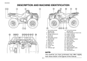
... 6. Air filter case 11. Engine oil dipstick 18. Fuel tank cap 25. DESCRIPTION AND MACHINE IDENTIFICATION 1. Tail/brake light 13. Coolant reservoir 16. Drive select lever 22. Brake pedal 7. Front spring preload adjusting ring 14. Rear brake lever 19. Auxiliary DC jack 26. V-belt cooling duct check hose 15. Spark arrester 3. Fuel cock 10. Left handlebar switches 20. Main switch 24. Oil filter cartridge 17. Starter (choke) 21. Speedometer 23. Right handlebar switch 27. Radiator cap 9. V-belt case 8. Throttle lever 28. Fuses 12...
... 6. Air filter case 11. Engine oil dipstick 18. Fuel tank cap 25. DESCRIPTION AND MACHINE IDENTIFICATION 1. Tail/brake light 13. Coolant reservoir 16. Drive select lever 22. Brake pedal 7. Front spring preload adjusting ring 14. Rear brake lever 19. Auxiliary DC jack 26. V-belt cooling duct check hose 15. Spark arrester 3. Fuel cock 10. Left handlebar switches 20. Main switch 24. Oil filter cartridge 17. Starter (choke) 21. Speedometer 23. Right handlebar switch 27. Radiator cap 9. V-belt case 8. Throttle lever 28. Fuses 12...

Owners Manual
Page 24
... key to specification. CAUTION: _ G G The engine may cause damage to the engine. _ 4-2 Continuous use while the light is on to cool down for about 10 minutes. If this light comes on may overheat if the ATV is safe to do so and allow the engine to warn that the light is too hot. Coolant temperature warning light " Reverse indicator light "R" Four-wheel drive indicator light " " Neutral indicator light "N" " Coolant...
... key to specification. CAUTION: _ G G The engine may cause damage to the engine. _ 4-2 Continuous use while the light is on to cool down for about 10 minutes. If this light comes on may overheat if the ATV is safe to do so and allow the engine to warn that the light is too hot. Coolant temperature warning light " Reverse indicator light "R" Four-wheel drive indicator light " " Neutral indicator light "N" " Coolant...

Owners Manual
Page 27
... switch is turned to " ". The engine stop switch controls ignition and can be used at all the lights. 4-5 Engine stop switch " "/" " Make sure that the starter motor will not start or run when the engine stop switch is in an emergency. Light switch " / /OFF" 2. Set the switch to "OFF" to turn on the low beam and the taillight. EBU00053 Handlebar switches _ CAUTION: Do not use the headlights with the engine turned off all times...
... switch is turned to " ". The engine stop switch controls ignition and can be used at all the lights. 4-5 Engine stop switch " "/" " Make sure that the starter motor will not start or run when the engine stop switch is in an emergency. Light switch " / /OFF" 2. Set the switch to "OFF" to turn on the low beam and the taillight. EBU00053 Handlebar switches _ CAUTION: Do not use the headlights with the engine turned off all times...
Owners Manual
Page 30
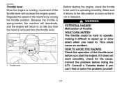
... be sure it does not work smoothly, check for the cause. Correct the problem before you start the engine. Because the throttle is released. Regulate the speed of the machine by varying the throttle position. Throttle lever 4-8 Before starting the engine, check the throttle to the idle position as soon as the lever is spring-loaded, the machine will decelerate, and the engine will increase the engine speed.
... be sure it does not work smoothly, check for the cause. Correct the problem before you start the engine. Because the throttle is released. Regulate the speed of the machine by varying the throttle position. Throttle lever 4-8 Before starting the engine, check the throttle to the idle position as soon as the lever is spring-loaded, the machine will decelerate, and the engine will increase the engine speed.
Owners Manual
Page 47
... adjustment procedures provided in this manual, have a Yamaha dealer check for one minute. Brake operation Test the brakes at the start of the pipe joints or brake fluid reservoirs. Brake fluid leakage Check to see if any brake fluid is any problem with improperly operating brakes. If the brakes do not provide proper braking performance, inspect the brake pads for wear. (See page 8-37.) WARNING POTENTIAL HAZARD Riding with the...
... adjustment procedures provided in this manual, have a Yamaha dealer check for one minute. Brake operation Test the brakes at the start of the pipe joints or brake fluid reservoirs. Brake fluid leakage Check to see if any brake fluid is any problem with improperly operating brakes. If the brakes do not provide proper braking performance, inspect the brake pads for wear. (See page 8-37.) WARNING POTENTIAL HAZARD Riding with the...
Owners Manual
Page 58
... being familiar with all control cables work smoothly before you do not understand, ask your Yamaha dealer. 6-1 Apply the rear brake lever. 2. Shift the drive select lever into the neutral position. HOW TO AVOID THE HAZARD When riding in serious injury or death. HOW TO AVOID THE HAZARD Read the Owner's Manual carefully. EBU00161 1- EBU01109 OPERATION Starting a cold engine WARNING Indicates a potential hazard...
... being familiar with all control cables work smoothly before you do not understand, ask your Yamaha dealer. 6-1 Apply the rear brake lever. 2. Shift the drive select lever into the neutral position. HOW TO AVOID THE HAZARD When riding in serious injury or death. HOW TO AVOID THE HAZARD Read the Owner's Manual carefully. EBU00161 1- EBU01109 OPERATION Starting a cold engine WARNING Indicates a potential hazard...

Owners Manual
Page 65
Rev the machine freely but do not use full throttle at any time. 3. EBU00211 2. 10-20 hours: Avoid prolonged operation above 3/4 throttle. Parking When parking, stop the engine and shift into neutral. Turn the fuel cock to "OFF" and apply the parking brake. 6-8 After break-in: Avoid prolonged full throttle operation. Vary speeds occasionally.
Rev the machine freely but do not use full throttle at any time. 3. EBU00211 2. 10-20 hours: Avoid prolonged operation above 3/4 throttle. Parking When parking, stop the engine and shift into neutral. Turn the fuel cock to "OFF" and apply the parking brake. 6-8 After break-in: Avoid prolonged full throttle operation. Vary speeds occasionally.

Owners Manual
Page 114
... hose for leakage. Replace. (Warm engine before draining.) Replace. Clean. Clean. Check operation/fluid leakage. (See NOTE page 8-4.) Correct if necessary. Replace coolant every 24 months. Clean. Repair if necessary. Replace if necessary. Replace if necessary. Adjust if necessary. 1 month INITIAL EVERY 3 6 6 1 months months months year Spark plug Air filter element Carburetor* Crankcase breather system* Exhaust system* Spark arrester Fuel line* Engine oil Engine oil filter cartridge Engine oil strainer* Final gear oil Differential gear oil Front brake* Rear brake...
... hose for leakage. Replace. (Warm engine before draining.) Replace. Clean. Clean. Check operation/fluid leakage. (See NOTE page 8-4.) Correct if necessary. Replace coolant every 24 months. Clean. Repair if necessary. Replace if necessary. Replace if necessary. Adjust if necessary. 1 month INITIAL EVERY 3 6 6 1 months months months year Spark plug Air filter element Carburetor* Crankcase breather system* Exhaust system* Spark arrester Fuel line* Engine oil Engine oil filter cartridge Engine oil strainer* Final gear oil Differential gear oil Front brake* Rear brake...

Owners Manual
Page 115
... 4 G Brake fluid replacement: • When disassembling the master cylinder or caliper, replace the brake fluid. Wheel bearing* • Replace if damaged. Steering system* • Check toe-in serious injury or death. Wheels* • Repair if necessary. • Check bearing assemblies for cracks or damage. • Check balance/damage/runout. Axle boots* • Replace if damaged. • Check all chassis fittings and fasteners. Front and rear • Check operation...
... 4 G Brake fluid replacement: • When disassembling the master cylinder or caliper, replace the brake fluid. Wheel bearing* • Replace if damaged. Steering system* • Check toe-in serious injury or death. Wheels* • Repair if necessary. • Check bearing assemblies for cracks or damage. • Check balance/damage/runout. Axle boots* • Replace if damaged. • Check all chassis fittings and fasteners. Front and rear • Check operation...

Owners Manual
Page 132
... level mark 3. Coolant reservoir drain hose 2. Coolant reservoir capacity: 0.25 L (0.22 Imp qt, 0.26 US qt) 1. EBU01068 Cooling system 1. Check the coolant level in the coolant reservoir when the engine is low, remove panel D. (See pages 8-6-8-7 for panel removal and installation procedures.) 8-21 If the level is cold as the coolant level will vary with engine temperature. Install the panel. Coolant reservoir cap 2. Minimum level mark...
... level mark 3. Coolant reservoir drain hose 2. Coolant reservoir capacity: 0.25 L (0.22 Imp qt, 0.26 US qt) 1. EBU01068 Cooling system 1. Check the coolant level in the coolant reservoir when the engine is low, remove panel D. (See pages 8-6-8-7 for panel removal and installation procedures.) 8-21 If the level is cold as the coolant level will vary with engine temperature. Install the panel. Coolant reservoir cap 2. Minimum level mark...

Owners Manual
Page 135
Remove the coolant reservoir cap. 7. Remove the radiator cap. 6. Coolant reservoir drain hose 5. Tightening torque: Coolant drain bolt: 10 Nm (1.0 m·kgf, 7 ft·lbf) 8-24 Replace the coolant drain bolt washer if it is damaged, and then tighten the coolant drain bolt to the specified torque. Disconnect the hose on the coolant reservoir side, and then drain the coolant from the coolant reservoir. 8. Radiator cap 1. 1. After draining the coolant, thoroughly flush the cooling system with clean tap water. 9.
Remove the coolant reservoir cap. 7. Remove the radiator cap. 6. Coolant reservoir drain hose 5. Tightening torque: Coolant drain bolt: 10 Nm (1.0 m·kgf, 7 ft·lbf) 8-24 Replace the coolant drain bolt washer if it is damaged, and then tighten the coolant drain bolt to the specified torque. Disconnect the hose on the coolant reservoir side, and then drain the coolant from the coolant reservoir. 8. Radiator cap 1. 1. After draining the coolant, thoroughly flush the cooling system with clean tap water. 9.

Owners Manual
Page 155
... when the brake light comes on later, turn the adjusting nut in direction a. If necessary, adjust the brake light switch as follows. 1. Turn the adjusting nut while holding the rear brake light switch in direction b. 1. Adjusting nut 8-44 To make the brake light come on just before braking takes effect. To make the brake light come on earlier, turn the adjusting nut in place. Rear brake light switch 2. Remove panel B. (See page...
... when the brake light comes on later, turn the adjusting nut in direction a. If necessary, adjust the brake light switch as follows. 1. Turn the adjusting nut while holding the rear brake light switch in direction b. 1. Adjusting nut 8-44 To make the brake light come on just before braking takes effect. To make the brake light come on earlier, turn the adjusting nut in place. Rear brake light switch 2. Remove panel B. (See page...

Owners Manual
Page 156
... do not operate smoothly, ask a Yamaha dealer to replace them. Operation of control cables becomes damaged. HOW TO AVOID THE HAZARD Inspect cables frequently. Recommended lubricant: Yamaha chain and cable lube or SAE 10W30 motor oil 8-45 Brake lever and brake pedal lubrication Lubricate the pivoting parts. Cables can result when the outer covering of controls could be restricted, which could...
... do not operate smoothly, ask a Yamaha dealer to replace them. Operation of control cables becomes damaged. HOW TO AVOID THE HAZARD Inspect cables frequently. Recommended lubricant: Yamaha chain and cable lube or SAE 10W30 motor oil 8-45 Brake lever and brake pedal lubrication Lubricate the pivoting parts. Cables can result when the outer covering of controls could be restricted, which could...

Owners Manual
Page 161
Headlight fuse Ignition fuse Auxiliary DC jack fuse Four-wheel drive fuse Signaling system fuse Spare fuse (× 3) Specified fuses: Main fuse: Headlight fuse: Ignition fuse: Auxiliary DC jack fuse: Four-wheel drive fuse: Signaling system fuse: 8-50 30A 15A 10A 10A 3A 10A 1. Main fuse 2. Spare main fuse 1. 2. 3. 4. 5. 6.
Headlight fuse Ignition fuse Auxiliary DC jack fuse Four-wheel drive fuse Signaling system fuse Spare fuse (× 3) Specified fuses: Main fuse: Headlight fuse: Ignition fuse: Auxiliary DC jack fuse: Four-wheel drive fuse: Signaling system fuse: 8-50 30A 15A 10A 10A 3A 10A 1. Main fuse 2. Spare main fuse 1. 2. 3. 4. 5. 6.
Owners Manual
Page 168
... but will improve its general performance and extend the useful life of wheel bearings, brakes, transmission seals and electrical devices. If the engine case is handy for hard-to prevent water entry. Many expensive repair bills have resulted from improper high pressure detergent applications such as those available in coin-operated car washers. 4. A. Once the majority of the exhaust pipe to -get-at places...
... but will improve its general performance and extend the useful life of wheel bearings, brakes, transmission seals and electrical devices. If the engine case is handy for hard-to prevent water entry. Many expensive repair bills have resulted from improper high pressure detergent applications such as those available in coin-operated car washers. 4. A. Once the majority of the exhaust pipe to -get-at places...

Owners Manual
Page 170
... to each liter of fuel) NOTE: Use of SAE 10W30 or 20W40 motor oil in a humid or salt-air atmosphere, coat all exposed metal surfaces with oil. 3. Block up the frame to prevent moisture from entering. 6. If storing in the spark plug hole and reinstall the spark plug. Ground the spark plug wire and turn the engine over the exhaust pipe outlet to raise all control cables. 4.
... to each liter of fuel) NOTE: Use of SAE 10W30 or 20W40 motor oil in a humid or salt-air atmosphere, coat all exposed metal surfaces with oil. 3. Block up the frame to prevent moisture from entering. 6. If storing in the spark plug hole and reinstall the spark plug. Ground the spark plug wire and turn the engine over the exhaust pipe outlet to raise all control cables. 4.

Owners Manual
Page 177
Model Bulb voltage, wattage × quantity: Headlight Tail/brake light Meter lighting Neutral indicator light Reverse indicator light Coolant temperature warning light Four-wheel drive indicator light Fuses: Main fuse Headlight fuse Ignition fuse Auxiliary DC jack fuse Four-wheel drive fuse Signaling system fuse 12 V, 30/30 W × 2 12 V, 5/21 W × 1 14 V, 3 W × 1 12 V, 1.7 W × 1 12 V, 1.7 W × 1 12 V, 1.7 W × 1 12 V, 1.7 W × 1 30 A 15 A 10 A 10 A 3A 10 A YFM400FAR 10-6
Model Bulb voltage, wattage × quantity: Headlight Tail/brake light Meter lighting Neutral indicator light Reverse indicator light Coolant temperature warning light Four-wheel drive indicator light Fuses: Main fuse Headlight fuse Ignition fuse Auxiliary DC jack fuse Four-wheel drive fuse Signaling system fuse 12 V, 30/30 W × 2 12 V, 5/21 W × 1 14 V, 3 W × 1 12 V, 1.7 W × 1 12 V, 1.7 W × 1 12 V, 1.7 W × 1 12 V, 1.7 W × 1 30 A 15 A 10 A 10 A 3A 10 A YFM400FAR 10-6