
Owners Manual
Page 7
... switches ...3-2 Clutch lever ...3-3 Shift pedal ...3-3 Brake lever ...3-4 Brake pedal ...3-4 Fuel tank cap ...3-4 Fuel ...3-5 Fuel cock ...3-6 Starter (choke) lever ...3-7 Steering lock ...3-8 Rider seat ...3-8 Helmet holder ...3-9 Adjusting the shock absorber assemblies ...3-10 Sidestand ...3-10 Ignition circuit cut-off system ...3-11 1 4 PRE-OPERATION CHECKS ...4-1 Pre-operation check list ...4-1 OPERATION AND IMPORTANT RIDING POINTS ...5-1 Starting and warming up a cold engine ...5-2 Starting a warm engine ...5-3 Shifting ...5-4 Engine break-in ...5-5 Parking ...5-6 PERIODIC MAINTENANCE...
... switches ...3-2 Clutch lever ...3-3 Shift pedal ...3-3 Brake lever ...3-4 Brake pedal ...3-4 Fuel tank cap ...3-4 Fuel ...3-5 Fuel cock ...3-6 Starter (choke) lever ...3-7 Steering lock ...3-8 Rider seat ...3-8 Helmet holder ...3-9 Adjusting the shock absorber assemblies ...3-10 Sidestand ...3-10 Ignition circuit cut-off system ...3-11 1 4 PRE-OPERATION CHECKS ...4-1 Pre-operation check list ...4-1 OPERATION AND IMPORTANT RIDING POINTS ...5-1 Starting and warming up a cold engine ...5-2 Starting a warm engine ...5-3 Shifting ...5-4 Engine break-in ...5-5 Parking ...5-6 PERIODIC MAINTENANCE...

Owners Manual
Page 8
... ...6-31 Replacing the headlight bulb ...6-32 Supporting the motorcycle ...6-33 Front wheel ...6-34 Rear wheel ...6-36 Troubleshooting ...6-37 Troubleshooting chart ...6-38 7 MOTORCYCLE CARE AND STORAGE ...7-1 Care ...7-1 Storage ...7-4 SPECIFICATIONS...8-1 Specifications ...8-1 CONSUMER INFORMATION...9-1 Identification numbers ...9-1 Key identification number ...9-1 Vehicle identification number ...9-1 Model label ...9-2 REPORTING SAFETY DEFECTS ...9-3 MOTORCYCLE NOISE REGULATION ...9-4 Maintenance record ...9-5 Street and enduro motorcycle limited warranty...9-7 Yamaha extended service...
... ...6-31 Replacing the headlight bulb ...6-32 Supporting the motorcycle ...6-33 Front wheel ...6-34 Rear wheel ...6-36 Troubleshooting ...6-37 Troubleshooting chart ...6-38 7 MOTORCYCLE CARE AND STORAGE ...7-1 Care ...7-1 Storage ...7-4 SPECIFICATIONS...8-1 Specifications ...8-1 CONSUMER INFORMATION...9-1 Identification numbers ...9-1 Key identification number ...9-1 Vehicle identification number ...9-1 Model label ...9-2 REPORTING SAFETY DEFECTS ...9-3 MOTORCYCLE NOISE REGULATION ...9-4 Maintenance record ...9-5 Street and enduro motorcycle limited warranty...9-7 Yamaha extended service...

Owners Manual
Page 12
... front fender. Shifting weights can create unstable handling or slow steering response. Check accessory mounts and cargo restraints frequently. 3. These items, including such cargo as possible on this weight limit, keep the following guidelines in mind, as well as possible. Use extreme caution when selecting and installing any way reduce ground clearance or cornering clearance, limit suspension travel, steering travel or control...
... front fender. Shifting weights can create unstable handling or slow steering response. Check accessory mounts and cargo restraints frequently. 3. These items, including such cargo as possible on this weight limit, keep the following guidelines in mind, as well as possible. Use extreme caution when selecting and installing any way reduce ground clearance or cornering clearance, limit suspension travel, steering travel or control...
Owners Manual
Page 13
... lights or engine power. 1 Gasoline and exhaust gas 1. If electrical accessories exceed the capacity of the motorcycle's electrical system, an electric failure could result, which could cause a dangerous loss of an open flame. 2. c. Never refuel while smoking or in cross winds. If accessories are poisonous and may cause loss of consciousness and death within a short time. GASOLINE IS HIGHLY FLAMMABLE: a. Never start the engine...
... lights or engine power. 1 Gasoline and exhaust gas 1. If electrical accessories exceed the capacity of the motorcycle's electrical system, an electric failure could result, which could cause a dangerous loss of an open flame. 2. c. Never refuel while smoking or in cross winds. If accessories are poisonous and may cause loss of consciousness and death within a short time. GASOLINE IS HIGHLY FLAMMABLE: a. Never start the engine...
Owners Manual
Page 20
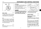
... time, otherwise the battery may discharge. @ @ 3 1. ECA00043 EAU00028 Main switch The main switch controls the ignition and lighting systems. The various main switch positions are on . Turn signal indicator light "TURN" EAU00056 Indicator lights EAU00064 ON All electrical systems are supplied with power, the headlight, meter lighting, taillight and front position lights come on when the transmission is pushed to be started. EAU00062 Neutral indicator light "NEUTRAL" This indicator light comes on , and the engine...
... time, otherwise the battery may discharge. @ @ 3 1. ECA00043 EAU00028 Main switch The main switch controls the ignition and lighting systems. The various main switch positions are on . Turn signal indicator light "TURN" EAU00056 Indicator lights EAU00064 ON All electrical systems are supplied with power, the headlight, meter lighting, taillight and front position lights come on when the transmission is pushed to be started. EAU00062 Neutral indicator light "NEUTRAL" This indicator light comes on , and the engine...
Owners Manual
Page 22
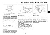
... is used in case of the 5-speed constant-mesh transmission equipped on this switch to "OFF" to "RUN" before starting the engine. @ @ 3-3 Start switch "START" Push this switch to stop the engine in combination with the starter. To disengage the clutch, pull the lever toward the handlebar grip. To engage the clutch, release the lever. Shift pedal EAU00157 Engine stop switch "ENGINE STOP" 2. Clutch lever EAU00152 1. The lever should be...
... is used in case of the 5-speed constant-mesh transmission equipped on this switch to "OFF" to "RUN" before starting the engine. @ @ 3-3 Start switch "START" Push this switch to stop the engine in combination with the starter. To disengage the clutch, pull the lever toward the handlebar grip. To engage the clutch, release the lever. Shift pedal EAU00157 Engine stop switch "ENGINE STOP" 2. Clutch lever EAU00152 1. The lever should be...
Owners Manual
Page 25
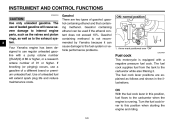
... this position, fuel flows to the fuel system or vehicle performance problems. ON: normal position 1. INSTRUMENT AND CONTROL FUNCTIONS ECA00104 3 CAUTION: Use only unleaded gasoline. Use of gasohol: gasohol containing ethanol and that containing methanol. If knocking (or pinging) occurs, use of a different brand or premium unleaded fuel. The use a gasoline of leaded gasoline will extend spark plug life and reduce maintenance costs.
... this position, fuel flows to the fuel system or vehicle performance problems. ON: normal position 1. INSTRUMENT AND CONTROL FUNCTIONS ECA00104 3 CAUTION: Use only unleaded gasoline. Use of gasohol: gasohol containing ethanol and that containing methanol. If knocking (or pinging) occurs, use of a different brand or premium unleaded fuel. The use a gasoline of leaded gasoline will extend spark plug life and reduce maintenance costs.
Owners Manual
Page 30
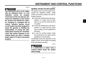
...starting when the transmission is in gear and the sidestand is moved down. G It cuts the running engine when the transmission is in gear and the clutch lever is pulled, but the clutch lever is not pulled. Periodically check the operation of control. EW000045 3 WARNING If a malfunction is noted, have a Yamaha dealer repair... could contact the ground and distract the operator, resulting in gear and the sidestand is up, but the sidestand is still down. Yamaha's ignition circuit cut -off system (comprising the sidestand switch, clutch switch and neutral switch) has the following...
...starting when the transmission is in gear and the sidestand is moved down. G It cuts the running engine when the transmission is in gear and the clutch lever is pulled, but the clutch lever is not pulled. Periodically check the operation of control. EW000045 3 WARNING If a malfunction is noted, have a Yamaha dealer repair... could contact the ground and distract the operator, resulting in gear and the sidestand is up, but the sidestand is still down. Yamaha's ignition circuit cut -off system (comprising the sidestand switch, clutch switch and neutral switch) has the following...
Owners Manual
Page 31
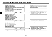
... gear. 9. Does the engine start switch. Keep the clutch lever pulled. 8. Move the sidestand up . 7. INSTRUMENT AND CONTROL FUNCTIONS CD-01E With the engine turned off: 1. Move the sidestand down . Make sure that the engine stop switch is most reliable if performed with a warmed-up engine. 3 YES With the engine still running: 6. Keep the clutch lever pulled. 12. YES NO The clutch switch may be defective. Shift the transmission into the neutral...
... gear. 9. Does the engine start switch. Keep the clutch lever pulled. 8. Move the sidestand up . 7. INSTRUMENT AND CONTROL FUNCTIONS CD-01E With the engine turned off: 1. Move the sidestand down . Make sure that the engine stop switch is most reliable if performed with a warmed-up engine. 3 YES With the engine still running: 6. Keep the clutch lever pulled. 12. YES NO The clutch switch may be defective. Shift the transmission into the neutral...

Owners Manual
Page 32
Any damage, fluid leakage or loss of tire air pressure could have Yamaha dealer bleed hydraulic system. Check oil level in fuel tank. Adjust if necessary. Adjust if necessary. Check operation. Therefore, it is the owner's responsibility. EAU03439 Pre-operation check list CO-01E ITEM Fuel Engine oil Front brake Rear brake Clutch Throttle grip Control cables CHECKS Check fuel level in engine. If necessary, add recommended oil to specified level. Check...
Any damage, fluid leakage or loss of tire air pressure could have Yamaha dealer bleed hydraulic system. Check oil level in fuel tank. Adjust if necessary. Adjust if necessary. Check operation. Therefore, it is the owner's responsibility. EAU03439 Pre-operation check list CO-01E ITEM Fuel Engine oil Front brake Rear brake Clutch Throttle grip Control cables CHECKS Check fuel level in engine. If necessary, add recommended oil to specified level. Check...

Owners Manual
Page 33
... water if necessary. Tighten if necessary. and the added safety it inspected and repaired before operating the motorcycle. _ _ 4-2 Make sure that operation is smooth. Check air pressure. Lubricate lever pivoting points if necessary. PAGE 6-22-6-23 Wheels and tires 6-14-6-16 Brake and shift pedals 6-26 6-26 6-27 - - 3-10-3-11 6-29-6-30 4 Brake and clutch levers Sidestand Chassis fasteners Instruments, lights, signals and switches Sidestand switch Battery...
... water if necessary. Tighten if necessary. and the added safety it inspected and repaired before operating the motorcycle. _ _ 4-2 Make sure that operation is smooth. Check air pressure. Lubricate lever pivoting points if necessary. PAGE 6-22-6-23 Wheels and tires 6-14-6-16 Brake and shift pedals 6-26 6-26 6-27 - - 3-10-3-11 6-29-6-30 4 Brake and clutch levers Sidestand Chassis fasteners Instruments, lights, signals and switches Sidestand switch Battery...
Owners Manual
Page 35
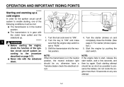
.... Turn the key to "ON" and make sure that the engine stop switch is in the neutral position, the neutral indicator light should be as short as possible to "RUN". 3. Shift the transmission into the neutral position. Turn the starter (choke) on and completely close the throttle. (See page 3-7 for the ignition circuit cut -off system to enable starting, one attempt. _ _ 5-2 Start the engine by pushing the start switch, wait...
.... Turn the key to "ON" and make sure that the engine stop switch is in the neutral position, the neutral indicator light should be as short as possible to "RUN". 3. Shift the transmission into the neutral position. Turn the starter (choke) on and completely close the throttle. (See page 3-7 for the ignition circuit cut -off system to enable starting, one attempt. _ _ 5-2 Start the engine by pushing the start switch, wait...
Owners Manual
Page 37
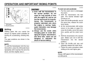
The transmission is properly lubricated only when the engine is running. G Always use the clutch while changing gears to avoid damaging the engine, transmission, and drive train, which are shown in the illustration. @ CAUTION: G Even with the engine off , accelerating, climbing hills, etc. Shift the transmission into the neutral position, press the shift pedal down repeatedly until it reaches the end of engine power available for starting off...
The transmission is properly lubricated only when the engine is running. G Always use the clutch while changing gears to avoid damaging the engine, transmission, and drive train, which are shown in the illustration. @ CAUTION: G Even with the engine off , accelerating, climbing hills, etc. Shift the transmission into the neutral position, press the shift pedal down repeatedly until it reaches the end of engine power available for starting off...
Owners Manual
Page 42
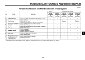
PERIODIC MAINTENANCE AND MINOR REPAIR EAU00471 Periodic maintenance chart for California only) √ √ √ 6 * Since these items require special tools, data and technical skills, have a Yamaha dealer perform the service. 6-3 Crankcase ventilation 3 * system 4 * Fuel line 5 * Exhaust system 6 * Idle speed Evaporative emission 7 * control system (for the emission control system No. ITEM ROUTINE INITIAL 600 mi (1,000km) or 1 month 4,000 mi (6,000km) or 6 months...
PERIODIC MAINTENANCE AND MINOR REPAIR EAU00471 Periodic maintenance chart for California only) √ √ √ 6 * Since these items require special tools, data and technical skills, have a Yamaha dealer perform the service. 6-3 Crankcase ventilation 3 * system 4 * Fuel line 5 * Exhaust system 6 * Idle speed Evaporative emission 7 * control system (for the emission control system No. ITEM ROUTINE INITIAL 600 mi (1,000km) or 1 month 4,000 mi (6,000km) or 6 months...

Owners Manual
Page 43
...; √ √ √ Engine oil filter 2 * element 3 * Air filter element √ √ √ √ 4 * Brake system - √ √ √ √ √ √ Every 300 mi (500 km) √ √ √ √ 6 5 * Clutch 6 Drive chain Control and meter cable - pivot shafts Brake and shift pedal pivot shafts • Lubricate. • Apply chain lube lightly. • Check operation and lubricate. • Apply chain lube lightly. 11 * Sidestand pivot...
...; √ √ √ Engine oil filter 2 * element 3 * Air filter element √ √ √ √ 4 * Brake system - √ √ √ √ √ √ Every 300 mi (500 km) √ √ √ √ 6 5 * Clutch 6 Drive chain Control and meter cable - pivot shafts Brake and shift pedal pivot shafts • Lubricate. • Apply chain lube lightly. • Check operation and lubricate. • Apply chain lube lightly. 11 * Sidestand pivot...

Owners Manual
Page 44
... the maintenance intervals starting from 4,000 mi (6,000 km) or 6 months. _ _ EAU03057 NOTE: G The air filter needs more frequent service if you are riding in unusually wet or dusty areas. Check the brake fluid level regularly and fill as required. • Replace the oil seals on the inner parts of the master cylinder and caliper cylinder every two years. • Replace the brake hoses...
... the maintenance intervals starting from 4,000 mi (6,000 km) or 6 months. _ _ EAU03057 NOTE: G The air filter needs more frequent service if you are riding in unusually wet or dusty areas. Check the brake fluid level regularly and fill as required. • Replace the oil seals on the inner parts of the master cylinder and caliper cylinder every two years. • Replace the brake hoses...

Owners Manual
Page 54
... the suspension for your load, and check the condition and pressure of your motorcycle, such as possible with a worn-out tire. Make sure the total weight of all wheeland brake-related parts, including the tires, should be left to show crosswise lines, have the tire replaced. CE-10E EAU00680 @ FRONT Manufacturer CHENG SHIN REAR Manufacturer Size Model C-915 Size 3.00-18 47P Model C-916...
... the suspension for your load, and check the condition and pressure of your motorcycle, such as possible with a worn-out tire. Make sure the total weight of all wheeland brake-related parts, including the tires, should be left to show crosswise lines, have the tire replaced. CE-10E EAU00680 @ FRONT Manufacturer CHENG SHIN REAR Manufacturer Size Model C-915 Size 3.00-18 47P Model C-916...

Owners Manual
Page 59
... a Yamaha dealer replace the brake pads as follows. Front 1. To make the brake light come on just before braking takes effect. To make the brake light come on later, turn the adjusting nut in direction b. 6-20 Front brake pads Each front brake pad is properly adjusted when the brake light comes on earlier, turn the adjusting nut in direction a. PERIODIC MAINTENANCE AND MINOR REPAIR EAU00720 Checking the front brake pads and rear brake...
... a Yamaha dealer replace the brake pads as follows. Front 1. To make the brake light come on just before braking takes effect. To make the brake light come on later, turn the adjusting nut in direction b. 6-20 Front brake pads Each front brake pad is properly adjusted when the brake light comes on earlier, turn the adjusting nut in direction a. PERIODIC MAINTENANCE AND MINOR REPAIR EAU00720 Checking the front brake pads and rear brake...

Owners Manual
Page 76
... repair bills. 6 WARNING After adjusting the brake pedal free play, check the operation of the brake light. _ _ WARNING Always use a new cotter pin for example, can cause poor starting and loss of power. Install the axle nut, and then lower the rear wheel so that it is on the ground. 3. Any problem in the fuel, compression, or ignition systems, for the axle nut. _ _ 6-37 Use only genuine Yamaha replacement...
... repair bills. 6 WARNING After adjusting the brake pedal free play, check the operation of the brake light. _ _ WARNING Always use a new cotter pin for example, can cause poor starting and loss of power. Install the axle nut, and then lower the rear wheel so that it is on the ground. 3. Any problem in the fuel, compression, or ignition systems, for the axle nut. _ _ 6-37 Use only genuine Yamaha replacement...

Owners Manual
Page 83
SPECIFICATIONS Model Dimensions Overall length Overall width Overall height Seat height Wheelbase Ground clearance Minimum turning radius Basic weight (with a diesel specification of "CD" or oils of a higher quality than specified. Do not use oils with oil and full fuel tank) XV250 XV250C Engine Engine type Cylinder arrangement Air-cooled 4-stroke, SOHC V-type 2-cylinder 249 cm3 49 × 66 mm (1.93 × 2.60 in) 10:1 Electric starter Wet sump 147 kg (324 lb) 148 kg...
SPECIFICATIONS Model Dimensions Overall length Overall width Overall height Seat height Wheelbase Ground clearance Minimum turning radius Basic weight (with a diesel specification of "CD" or oils of a higher quality than specified. Do not use oils with oil and full fuel tank) XV250 XV250C Engine Engine type Cylinder arrangement Air-cooled 4-stroke, SOHC V-type 2-cylinder 249 cm3 49 × 66 mm (1.93 × 2.60 in) 10:1 Electric starter Wet sump 147 kg (324 lb) 148 kg...