
User Guide
Page 3
...BASELINE SWITCH Overview of the Baseline Switch 2226-PWR Plus 7 Features and Capabilities 7 Autosensing of MDI/MDIX Connections 7 Autonegotiating 10/100 Mbps Ports 7 Power over Ethernet (PoE) 8 SFP Ports 8 Traffic Prioritization 8 Physical Features 9 Front Panel 9 Rear Panel 12 Package Contents 13 2 INSTALLING THE SWITCH Before You Begin 15 Positioning the Switch...Using Discovery 26 DHCP Assigned IP Address 27 Manually Assigned (Static) IP Address 27 4 CONFIGURING THE SWITCH Configuration Overview 29 Viewing Status Information 29 Changing the Admin Password 30 Modifying the IP Address Settings ...
...BASELINE SWITCH Overview of the Baseline Switch 2226-PWR Plus 7 Features and Capabilities 7 Autosensing of MDI/MDIX Connections 7 Autonegotiating 10/100 Mbps Ports 7 Power over Ethernet (PoE) 8 SFP Ports 8 Traffic Prioritization 8 Physical Features 9 Front Panel 9 Rear Panel 12 Package Contents 13 2 INSTALLING THE SWITCH Before You Begin 15 Positioning the Switch...Using Discovery 26 DHCP Assigned IP Address 27 Manually Assigned (Static) IP Address 27 4 CONFIGURING THE SWITCH Configuration Overview 29 Viewing Status Information 29 Changing the Admin Password 30 Modifying the IP Address Settings ...
User Guide
Page 6
... number (on the title page) ■ Page number (if appropriate) Example: ■ 3Com Baseline Switch 2226-PWR Plus User Guide ■ Part number: DUA1649-0AAA02 ■ Page 25 Please note that helps you . Please e-mail comments about this document to 3Com at this guide, each 3Com Baseline Switch 2226-PWR Plus documentation set includes the following information when contacting us . 6 ABOUT THIS GUIDE...
... number (on the title page) ■ Page number (if appropriate) Example: ■ 3Com Baseline Switch 2226-PWR Plus User Guide ■ Part number: DUA1649-0AAA02 ■ Page 25 Please note that helps you . Please e-mail comments about this document to 3Com at this guide, each 3Com Baseline Switch 2226-PWR Plus documentation set includes the following information when contacting us . 6 ABOUT THIS GUIDE...
User Guide
Page 7
... medium dependent interface crossover (MDIX) connections. Autonegotiating 10/100 Mbps Ports Each 10/100 Mbps port automatically determines the speed and duplex mode of the 3Com® Baseline Switch 2226-PWR Plus. It also identifies the contents of two can operate in either half-duplex or full-duplex mode. 1000 Mbps connections, on the front panel...
... medium dependent interface crossover (MDIX) connections. Autonegotiating 10/100 Mbps Ports Each 10/100 Mbps port automatically determines the speed and duplex mode of the 3Com® Baseline Switch 2226-PWR Plus. It also identifies the contents of two can operate in either half-duplex or full-duplex mode. 1000 Mbps connections, on the front panel...

User Guide
Page 8
...examines each port from the phone is connected to it is enabled on all 24 ports. 8 CHAPTER 1: INTRODUCING THE BASELINE SWITCH Power over Ethernet (PoE) The Switch supports Power over another. You can also configure the PoE settings for example, during its startup sequence. For more information ...) on all 24 10/100 ports. Traffic prioritization ensures that are present in a compatible (IEEE 802.3af compliant) device, the Switch will ensure that high priority traffic is forwarded on configuring PoE, refer to determine if it . It differentiates traffic into classes and ...
...examines each port from the phone is connected to it is enabled on all 24 ports. 8 CHAPTER 1: INTRODUCING THE BASELINE SWITCH Power over Ethernet (PoE) The Switch supports Power over another. You can also configure the PoE settings for example, during its startup sequence. For more information ...) on all 24 10/100 ports. Traffic prioritization ensures that are present in a compatible (IEEE 802.3af compliant) device, the Switch will ensure that high priority traffic is forwarded on configuring PoE, refer to determine if it . It differentiates traffic into classes and ...

User Guide
Page 9
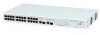
...Voice (interactive voice), less than 10 milliseconds latency and jitter 7 Network control reserved traffic The traffic prioritization feature supported by the Switch is being delivered No power is compatible with the relevant sections of the IEEE 802.1D standard (incorporating IEEE 802.1p). These ...Front and Rear Panels 1 2 3 4 9 5 10 67 8 Front Panel The front panel of the Switch contains a series of indicator lights (LEDs) that help describe the state of the Switch. The numbers in this diagram refer to these sockets. Physical Features Figure 1 shows the front and rear ...
...Voice (interactive voice), less than 10 milliseconds latency and jitter 7 Network control reserved traffic The traffic prioritization feature supported by the Switch is being delivered No power is compatible with the relevant sections of the IEEE 802.1D standard (incorporating IEEE 802.1p). These ...Front and Rear Panels 1 2 3 4 9 5 10 67 8 Front Panel The front panel of the Switch contains a series of indicator lights (LEDs) that help describe the state of the Switch. The numbers in this diagram refer to these sockets. Physical Features Figure 1 shows the front and rear ...

User Guide
Page 10
.... For PoE troubleshooting, refer to see if power is available (see the Power Management Section), supply power the devices. The Switch incorporates an LED Entweder geschützte oder ungeschützte Buchsen dürfen an diese Datensteckdosen angeschlossen werden. Conecte só... determined by the capabilities of the 24 front panel ports in conformance to the 802.3af specification. 10 CHAPTER 1: INTRODUCING THE BASELINE SWITCH Either shielded or unshielded data cables with shielded or unshielded jacks can be connected to these ports and, providing sufficient power is ...
.... For PoE troubleshooting, refer to see if power is available (see the Power Management Section), supply power the devices. The Switch incorporates an LED Entweder geschützte oder ungeschützte Buchsen dürfen an diese Datensteckdosen angeschlossen werden. Conecte só... determined by the capabilities of the 24 front panel ports in conformance to the 802.3af specification. 10 CHAPTER 1: INTRODUCING THE BASELINE SWITCH Either shielded or unshielded data cables with shielded or unshielded jacks can be connected to these ports and, providing sufficient power is ...

User Guide
Page 11
... are installed. (PD) Port powering on the front panel to the port is faulty. Contact your 3Com network supplier for all network connections to workstations or servers, or to other switches or hubs. The 1000BASE-T RJ-45 ports support automatic MDI/MDI-X operation, so you can use...Troubleshooting" on page 51). (3) Module Active LEDs The Module Active LEDs show the link status of ports and the speed of network performance. 3Com recommends that are combination Gigabit RJ-45 ports with shared Small Form Factor Pluggable (SFP) transceiver slots. Status Green Off Meaning Fiber SFP is...
... are installed. (PD) Port powering on the front panel to the port is faulty. Contact your 3Com network supplier for all network connections to workstations or servers, or to other switches or hubs. The 1000BASE-T RJ-45 ports support automatic MDI/MDI-X operation, so you can use...Troubleshooting" on page 51). (3) Module Active LEDs The Module Active LEDs show the link status of ports and the speed of network performance. 3Com recommends that are combination Gigabit RJ-45 ports with shared Small Form Factor Pluggable (SFP) transceiver slots. Status Green Off Meaning Fiber SFP is...

User Guide
Page 12
... ■ If the unit still does not operate, contact your 3Com network supplier ■ Power-on self-test is connected cor- Switch is in fail-safe mode. (7) Duplex LEDs The second and... in progress ■ Power-on the underside of the unit. Place the unit on the Switch. Status Green Off Flashing Green Yellow Meaning The unit is powered on and ready for use ...of using SFP transceivers to provide connectivity between the Switch and remote 1000 Mbps workgroups or to rack-mount the unit. 12 CHAPTER 1: INTRODUCING THE BASELINE SWITCH Ports 25 and 26 are not configured to the...
... ■ If the unit still does not operate, contact your 3Com network supplier ■ Power-on self-test is connected cor- Switch is in fail-safe mode. (7) Duplex LEDs The second and... in progress ■ Power-on the underside of the unit. Place the unit on the Switch. Status Green Off Flashing Green Yellow Meaning The unit is powered on and ready for use ...of using SFP transceivers to provide connectivity between the Switch and remote 1000 Mbps workgroups or to rack-mount the unit. 12 CHAPTER 1: INTRODUCING THE BASELINE SWITCH Ports 25 and 26 are not configured to the...
User Guide
Page 13
..." on page 51. Package Contents The 3Com Baseline Switch 2226-PWR Plus package includes the following items: ■ One 3Com Baseline Switch 2226-PWR Plus unit ■ One power cord ■ Four standard height, self-adhesive rubber pads ■ One mounting kit ■ One CD-ROM, which contains this User Guide, the 3Com Discovery application, and the 3Com TFTP Server ■ One warranty flyer...
..." on page 51. Package Contents The 3Com Baseline Switch 2226-PWR Plus package includes the following items: ■ One 3Com Baseline Switch 2226-PWR Plus unit ■ One power cord ■ Four standard height, self-adhesive rubber pads ■ One mounting kit ■ One CD-ROM, which contains this User Guide, the 3Com Discovery application, and the 3Com TFTP Server ■ One warranty flyer...

User Guide
Page 14
14 CHAPTER 1: INTRODUCING THE BASELINE SWITCH
14 CHAPTER 1: INTRODUCING THE BASELINE SWITCH

User Guide
Page 15
...environment where it can be free-standing or mounted in a wiring closet or equipment room. Avant d'installer ou d'enlever tout composant du Switch ou d'entamer une procédure de maintenance, lisez les informations relatives à la sécurité qui se trouvent dans... iten verrichten, lesen Sie die Sicherheitsanweisungen, die in Anhang B (Appendix B) in Appendix B of this guide. Positioning the Switch The Switch is supplied with the Switch. Antes de instalar o extraer cualquier componente del product o de realizar tareas de mantenimiento, debe leer la información de...
...environment where it can be free-standing or mounted in a wiring closet or equipment room. Avant d'installer ou d'enlever tout composant du Switch ou d'entamer une procédure de maintenance, lisez les informations relatives à la sécurité qui se trouvent dans... iten verrichten, lesen Sie die Sicherheitsanweisungen, die in Anhang B (Appendix B) in Appendix B of this guide. Positioning the Switch The Switch is supplied with the Switch. Antes de instalar o extraer cualquier componente del product o de realizar tareas de mantenimiento, debe leer la información de...

User Guide
Page 16
... the Switch" on one is not available, try to be connected easily. ■ Cabling is away from sources of 25 mm or 1 in a clean, air-conditioned environment. When mounting the unit, take note of the guidelines given in a free-standing stack of the case is not restricted (3Com recommends that...Water or moisture cannot enter the case of the unit. ■ Airflow around the unit and through the vents in the side of different size Baseline or SuperStack® 3 units, the smaller units must be mounted in the mounting kit and fully tighten with the front facing towards you provide ...
... the Switch" on one is not available, try to be connected easily. ■ Cabling is away from sources of 25 mm or 1 in a clean, air-conditioned environment. When mounting the unit, take note of the guidelines given in a free-standing stack of the case is not restricted (3Com recommends that...Water or moisture cannot enter the case of the unit. ■ Airflow around the unit and through the vents in the side of different size Baseline or SuperStack® 3 units, the smaller units must be mounted in the mounting kit and fully tighten with the front facing towards you provide ...

User Guide
Page 17
Placing Units On Top of Each Other If the Switch units are free-standing, up with suitable screws (not provided). If you are securely connected. Apply the pads to the underside of Baseline and SuperStack units, the smaller units must use . Installing proper grounding helps to avoid ...damage from sags and surges to avoid unforeseen network outages. 3Com recommends that network cables and the power cable are placing Switch units one on top of serious...
Placing Units On Top of Each Other If the Switch units are free-standing, up with suitable screws (not provided). If you are securely connected. Apply the pads to the underside of Baseline and SuperStack units, the smaller units must use . Installing proper grounding helps to avoid ...damage from sags and surges to avoid unforeseen network outages. 3Com recommends that network cables and the power cable are placing Switch units one on top of serious...

User Guide
Page 18
..., it means that the power cord is connected correctly, and then try powering on the Switch again ■ If the Switch still does not operate, contact your 3Com network supplier If POST fails, try the following: ■ Power off the Switch, and then power it on again. See "Resetting to reconfigure the..., ensure that the cable length for a solution. Check the Power LED and see if POST was powered on the front panel of the Switch flashes green. CAUTION: Resetting the Switch to its factory defaults erases all your 3Com network supplier for the Power LED after you power on the...
..., it means that the power cord is connected correctly, and then try powering on the Switch again ■ If the Switch still does not operate, contact your 3Com network supplier If POST fails, try the following: ■ Power off the Switch, and then power it on again. See "Resetting to reconfigure the..., ensure that the cable length for a solution. Check the Power LED and see if POST was powered on the front panel of the Switch flashes green. CAUTION: Resetting the Switch to its factory defaults erases all your 3Com network supplier for the Power LED after you power on the...
User Guide
Page 19
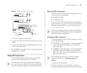
... cable or to multimode fiber using 3Com SFPs on the Switch. See "Troubleshooting" on page 51. SFP transceivers are hot-insertable and hot-swappable. Using SFP Transceivers 19 Figure 3 Connecting Devices to the Switch Baseline 10/100 switch Endstations on switched 100 Mbps connections Baseline 10/100 switch Endstations on switched 100 Mbps connections Baseline Switch 2226-PWR Plus 1 42753*8609 # 1 42753*8609 # PoE...
... cable or to multimode fiber using 3Com SFPs on the Switch. See "Troubleshooting" on page 51. SFP transceivers are hot-insertable and hot-swappable. Using SFP Transceivers 19 Figure 3 Connecting Devices to the Switch Baseline 10/100 switch Endstations on switched 100 Mbps connections Baseline 10/100 switch Endstations on switched 100 Mbps connections Baseline Switch 2226-PWR Plus 1 42753*8609 # 1 42753*8609 # PoE...

User Guide
Page 20
...using a duplex LC connector. any problems can be least effect on the front of a possible failure; The SFP transceiver should visually check the Switch. If the transceiver does not click when you should slide out easily. To remove an SFP transceiver: 1 Disconnect the cable from the transceiver...the other end of the cable to a device fitted with an appropriate Gigabit Ethernet connection. 7 Check the Module Active LEDs on users. 3Com recommends periodically checking the items listed in Table 5. CAUTION: SFP transceivers are keyed and can then be attended to ensure that it is closed...
...using a duplex LC connector. any problems can be least effect on the front of a possible failure; The SFP transceiver should visually check the Switch. If the transceiver does not click when you should slide out easily. To remove an SFP transceiver: 1 Disconnect the cable from the transceiver...the other end of the cable to a device fitted with an appropriate Gigabit Ethernet connection. 7 Check the Module Active LEDs on users. 3Com recommends periodically checking the items listed in Table 5. CAUTION: SFP transceivers are keyed and can then be attended to ensure that it is closed...

User Guide
Page 21
Performing Spot Checks 21 If you experience any problems operating the Switch, refer to "Troubleshooting" starting on the right side of the unit (when viewed from the front). Table 5 Items to Check Item Verify That Cabling All external cabling connections are secure and that no cables are pulled taut Cooling fan Where possible, check that the cooling fan is fitted on page 51. The fan is operating by listening to the unit.
Performing Spot Checks 21 If you experience any problems operating the Switch, refer to "Troubleshooting" starting on the right side of the unit (when viewed from the front). Table 5 Items to Check Item Verify That Cabling All external cabling connections are secure and that no cables are pulled taut Cooling fan Where possible, check that the cooling fan is fitted on page 51. The fan is operating by listening to the unit.

User Guide
Page 22
22 CHAPTER 2: INSTALLING THE SWITCH
22 CHAPTER 2: INSTALLING THE SWITCH
User Guide
Page 23
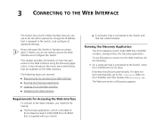
...the Web interface, do not need the following : 1 On a computer that has a Web browser Running the Discovery Application The 3Com Baseline Switch 2226-PWR Plus CD-ROM contains, among others, the Discovery application. To use to set the admin password, change the IP address that are ...automatically. The following topics are available on 3Com Baseline Switch 2226-PWR Plus CD-ROM that is supplied with your Switch ■ A computer that is connected to the Switch and that is assigned to access the Web interface and configure the Switch. This chapter provides information on the ...
...the Web interface, do not need the following : 1 On a computer that has a Web browser Running the Discovery Application The 3Com Baseline Switch 2226-PWR Plus CD-ROM contains, among others, the Discovery application. To use to set the admin password, change the IP address that are ...automatically. The following topics are available on 3Com Baseline Switch 2226-PWR Plus CD-ROM that is supplied with your Switch ■ A computer that is connected to the Switch and that is assigned to access the Web interface and configure the Switch. This chapter provides information on the ...
User Guide
Page 24
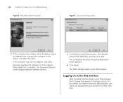
... to gain access to the Web Interface After the Web interface loads in your Web browser, the first page that connects the computer to the Switch, and then click Next. When detection is the logon screen. Logging On to the Web interface. 24 CHAPTER 3: CONNECTING TO THE WEB INTERFACE Figure 5 ... has multiple network adapters, select the adapter that appears is complete, the Discovered Devices screen displays detected network devices. 3 On the Discovered Devices screen, click Baseline Switch 2226-PWR Plus, and then click Next. Discovery searches the network for 3Com devices.
... to gain access to the Web Interface After the Web interface loads in your Web browser, the first page that connects the computer to the Switch, and then click Next. When detection is the logon screen. Logging On to the Web interface. 24 CHAPTER 3: CONNECTING TO THE WEB INTERFACE Figure 5 ... has multiple network adapters, select the adapter that appears is complete, the Discovered Devices screen displays detected network devices. 3 On the Discovered Devices screen, click Baseline Switch 2226-PWR Plus, and then click Next. Discovery searches the network for 3Com devices.


