User Guide
Page 3
Contents About this Guide Naming Convention 5 Conventions 5 Feedback about this User Guide 6 Product Registration 6 Introduction Baseline Switch 2816-SFP Plus 7 Package Contents 8 How to Use the Baseline Switch 2816-SFP Plus Front and Rear Panels 9 Front Panel Features 9 Rear Panel Features 11 Installation Recommendations Positioning the Switch 13 Rack Mounting or Free Standing 13 Power Supply 13 Power Up 13 Spot Checks...
Contents About this Guide Naming Convention 5 Conventions 5 Feedback about this User Guide 6 Product Registration 6 Introduction Baseline Switch 2816-SFP Plus 7 Package Contents 8 How to Use the Baseline Switch 2816-SFP Plus Front and Rear Panels 9 Front Panel Features 9 Rear Panel Features 11 Installation Recommendations Positioning the Switch 13 Rack Mounting or Free Standing 13 Power Supply 13 Power Up 13 Spot Checks...
User Guide
Page 5
... two or more keys simultaneously, the key names are linked with this 3Com Baseline Switch 2816-SFP Plus and contains information that are referred to as Twisted Pair Cables throughout this guide, the 3Com Baseline Switch 2816-SFP Plus is referred to as the Switch. Example: Press Ctrl+Alt+Del 5 Category 3 and Category 5 Twisted..." in Adobe Acrobat Reader Portable Document Format (PDF) on the 3Com World Wide Web site: http://www.3com.com Naming Convention Throughout this guide. ABOUT THIS GUIDE This guide is shipped with a plus sign (+). If a release note is intended for use by those...
... two or more keys simultaneously, the key names are linked with this 3Com Baseline Switch 2816-SFP Plus and contains information that are referred to as Twisted Pair Cables throughout this guide, the 3Com Baseline Switch 2816-SFP Plus is referred to as the Switch. Example: Press Ctrl+Alt+Del 5 Category 3 and Category 5 Twisted..." in Adobe Acrobat Reader Portable Document Format (PDF) on the 3Com World Wide Web site: http://www.3com.com Naming Convention Throughout this guide. ABOUT THIS GUIDE This guide is shipped with a plus sign (+). If a release note is intended for use by those...
User Guide
Page 6
...when commenting: ■ Document title ■ Document part number (on the title page) ■ Page number (if appropriate) Example: ■ 3Com Baseline Switch 2816-SFP Plus User Guide ■ Part Number DUA1648-5AAA0x ■ Page 24 Do not use this User Guide Your suggestions are used to: ■ Emphasize... the place where it is defined in italics Italics are very important to us. Product Registration You can now register your Baseline Switch on the 3Com web site to receive up-to-date information on page 37. Table 2 Text Conventions (continued) Convention Description Words in ...
...when commenting: ■ Document title ■ Document part number (on the title page) ■ Page number (if appropriate) Example: ■ 3Com Baseline Switch 2816-SFP Plus User Guide ■ Part Number DUA1648-5AAA0x ■ Page 24 Do not use this User Guide Your suggestions are used to: ■ Emphasize... the place where it is defined in italics Italics are very important to us. Product Registration You can now register your Baseline Switch on the 3Com web site to receive up-to-date information on page 37. Table 2 Text Conventions (continued) Convention Description Words in ...
User Guide
Page 7
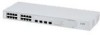
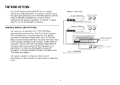
... in a wiring closet or equipment room). Figure 1 Network Plan Baseline 10/100 Switch Endstations on switched 100 Mbps connections Baseline 10/100 Switch Endstations on switched 100 Mbps connections BasBealinseliSnweiStcwhit2c8h1262-S5F0P Plus 1000 Mbps copper or Fiber connection to fiber-based Gigabit media. INTRODUCTION The 3Com® Baseline Switch 2816-SFP Plus is necessary. No configuration is a versatile, easy-to provide connectivity between...
... in a wiring closet or equipment room). Figure 1 Network Plan Baseline 10/100 Switch Endstations on switched 100 Mbps connections Baseline 10/100 Switch Endstations on switched 100 Mbps connections BasBealinseliSnweiStcwhit2c8h1262-S5F0P Plus 1000 Mbps copper or Fiber connection to fiber-based Gigabit media. INTRODUCTION The 3Com® Baseline Switch 2816-SFP Plus is necessary. No configuration is a versatile, easy-to provide connectivity between...

User Guide
Page 8
Package Contents The Switch comes with: ■ One power cord ■ Four standard height, self-adhesive rubber pads ■ One mounting kit ■ Installation CD ■ This User Guide ■ Warranty flyer The Switch is powered from the AC supply. 8
Package Contents The Switch comes with: ■ One power cord ■ Four standard height, self-adhesive rubber pads ■ One mounting kit ■ Installation CD ■ This User Guide ■ Warranty flyer The Switch is powered from the AC supply. 8
User Guide
Page 9
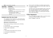
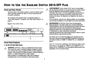
... die Verbindung der Einheit mit einem traditionellem privatem oder öffentlichem Telefonnetzwerk gebraucht werden. Figure 2 Front and Rear Panels 1 1 9 8 4 5 12 13 Baseline Switch 2816-SFP Plus 8 Module Present 3C16485 16 Link/Activity : Green = 1000M, Yellow = 10/1000M, Flash = Activity, Duplex : On = Full, Off = Half 2 ...233;seau téléphonique central privé ou public. HOW TO USE THE BASELINE SWITCH 2816-SFP PLUS Front and Rear Panels The front panel of the Switch contains a series of indicator lights (LEDs) that help describe the state of the connected...
... die Verbindung der Einheit mit einem traditionellem privatem oder öffentlichem Telefonnetzwerk gebraucht werden. Figure 2 Front and Rear Panels 1 1 9 8 4 5 12 13 Baseline Switch 2816-SFP Plus 8 Module Present 3C16485 16 Link/Activity : Green = 1000M, Yellow = 10/1000M, Flash = Activity, Duplex : On = Full, Off = Half 2 ...233;seau téléphonique central privé ou public. HOW TO USE THE BASELINE SWITCH 2816-SFP PLUS Front and Rear Panels The front panel of the Switch contains a series of indicator lights (LEDs) that help describe the state of the connected...
User Guide
Page 10
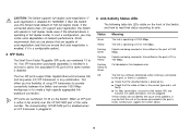
... some degradation of network performance. 3Com recommends that you use devices that are being received or transmitted on the port at 10 or 100 Mbps. In such a configuration, you may be that the unit or the device connected to 16. The four SFP ports support fiber Gigabit Ethernet short... the attached device is operating in . 3 Link/Activity Status LEDs The following table lists LEDs visible on the front of using SFP transceivers to provide connectivity between the Switch and remote 1000 Mbps workgroups or to the port, or there is a problem: ■ Check that the attached device is ...
... some degradation of network performance. 3Com recommends that you use devices that are being received or transmitted on the port at 10 or 100 Mbps. In such a configuration, you may be that the unit or the device connected to 16. The four SFP ports support fiber Gigabit Ethernet short... the attached device is operating in . 3 Link/Activity Status LEDs The following table lists LEDs visible on the front of using SFP transceivers to provide connectivity between the Switch and remote 1000 Mbps workgroups or to the port, or there is a problem: ■ Check that the attached device is ...
User Guide
Page 11
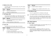
Status Green Off Meaning Fiber SFP is inserted in full-duplex mode. 6 Power LED The Power LED shows the power status of the Switch: Status Green Off Meaning The unit ...forgotten the default IP address, or forgotten your supplier. Rear Panel Features 8 Power Supply The Switch automatically adjusts to the factory default settings if, for use the power cord that are colored ... are installed. Status Flashing Green Yellow Meaning ■ Power-on self test or loopback test failed. Switch is in half-duplex mode. Status Off Yellow Meaning No link, not yet negotiated or the port...
Status Green Off Meaning Fiber SFP is inserted in full-duplex mode. 6 Power LED The Power LED shows the power status of the Switch: Status Green Off Meaning The unit ...forgotten the default IP address, or forgotten your supplier. Rear Panel Features 8 Power Supply The Switch automatically adjusts to the factory default settings if, for use the power cord that are colored ... are installed. Status Flashing Green Yellow Meaning ■ Power-on self test or loopback test failed. Switch is in half-duplex mode. Status Off Yellow Meaning No link, not yet negotiated or the port...
User Guide
Page 12
CAUTION: 3Com recommends that you back up your configuration settings before you recover the Switch, otherwise your configuration will be lost. Refer to "Configuration" on page 33 for details. 12
CAUTION: 3Com recommends that you back up your configuration settings before you recover the Switch, otherwise your configuration will be lost. Refer to "Configuration" on page 33 for details. 12
User Guide
Page 13
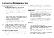
... 2 Connect the power supply cable to the power supply outlet socket and switch on the power supply at the socket. Static discharge can be mounted in .) clearance). ■ The air is not restricted (3Com recommends that you install power conditioning, especially in your system is not available...with a grounded rack and avoid touching the unit's ports and connectors, if possible. We recommend that you provide a minimum of different size Baseline or Superstack 3 units, the smaller units must be free standing. Use the following sequence to power up . Do not have a free-standing...
... 2 Connect the power supply cable to the power supply outlet socket and switch on the power supply at the socket. Static discharge can be mounted in .) clearance). ■ The air is not restricted (3Com recommends that you install power conditioning, especially in your system is not available...with a grounded rack and avoid touching the unit's ports and connectors, if possible. We recommend that you provide a minimum of different size Baseline or Superstack 3 units, the smaller units must be free standing. Use the following sequence to power up . Do not have a free-standing...
User Guide
Page 14
... hot-swappable. Where possible, check that no cables are pulled taut. If the SFP transceiver is operating by listening to the Switch use of cable for the Switch on users. any problems can then be least effect on the 3Com Corporation World Wide Web site, enter this transceiver to connect the... Switch directly to a single-mode fiber-optic cable or to insert an SFP transceiver into an SFP slot. You can give you an early warning of a possible failure; ...
... hot-swappable. Where possible, check that no cables are pulled taut. If the SFP transceiver is operating by listening to the Switch use of cable for the Switch on users. any problems can then be least effect on the 3Com Corporation World Wide Web site, enter this transceiver to connect the... Switch directly to a single-mode fiber-optic cable or to insert an SFP transceiver into an SFP slot. You can give you an early warning of a possible failure; ...
User Guide
Page 15
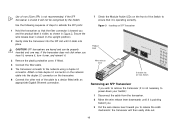
...you wish to remove the transceiver (it is not necessary to the network using a duplex LC connector. Use the following sequence of non-3Com SFPs is visible, as shown in the upright position). 2 Gently slide the transceiver into the duplex LC connector on the transceiver. 6 Connect the... end of the cable to a device fitted with an appropriate Gigabit Ethernet connection. 7 Check the Module Active LEDs on host Switch LiFnlka/sAhc=tivAitcyt : Removing an SFP Transceiver If you and the product label is not recommended. Attach a male duplex LC connector on the network cable into the...
...you wish to remove the transceiver (it is not necessary to the network using a duplex LC connector. Use the following sequence of non-3Com SFPs is visible, as shown in the upright position). 2 Gently slide the transceiver into the duplex LC connector on the transceiver. 6 Connect the... end of the cable to a device fitted with an appropriate Gigabit Ethernet connection. 7 Check the Module Active LEDs on host Switch LiFnlka/sAhc=tivAitcyt : Removing an SFP Transceiver If you and the product label is not recommended. Attach a male duplex LC connector on the network cable into the...
User Guide
Page 17
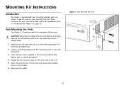
... will fit in a standard 19-inch rack. Rack Mounting the Units The Switch is supplied with suitable screws (not provided). 6 Reconnect the cables. Figure 4 Back Mounting the Units Baseline Switch 2816-SFP Plus 17 Remove the self-adhesive pads from the unit before continuing. These are ...used for the other side of the unit. 3 Insert the two screws supplied in "Positioning the Switch" on one side of the unit. 5 ...
... will fit in a standard 19-inch rack. Rack Mounting the Units The Switch is supplied with suitable screws (not provided). 6 Reconnect the cables. Figure 4 Back Mounting the Units Baseline Switch 2816-SFP Plus 17 Remove the self-adhesive pads from the unit before continuing. These are ...used for the other side of the unit. 3 Insert the two screws supplied in "Positioning the Switch" on one side of the unit. 5 ...
User Guide
Page 19
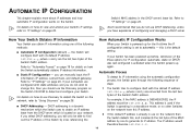
... default IP address 169.254.x.y,where x and y are the last two bytes of steps: 1 The Switch tries to generate its IP address. For example, if the MAC address is already in use on page 23. 3Com recommends that you will configure itself with its IP information using one to configure itself with...
... default IP address 169.254.x.y,where x and y are the last two bytes of steps: 1 The Switch tries to generate its IP address. For example, if the MAC address is already in use on page 23. 3Com recommends that you will configure itself with its IP information using one to configure itself with...

User Guide
Page 20
3 The Switch repeats step 2 until an unused IP address is found. 20
3 The Switch repeats step 2 until an unused IP address is found. 20
User Guide
Page 21
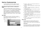
... the system up and maintain trunk membership for port groups. ■ Traffic Monitoring - displays the current status and activity logs of the Switch. ■ Port Configuration - Click this button for further assistance and guidance relating to change the system password. ■ IP settings -...password. allows the administrator to the context-sensitive online help system and 3Com contact information. Main Menu At the left side of all the options available through the use the new IP address instead. SWITCH CONFIGURATION This chapter describes all screens is a main menu, as ...
... the system up and maintain trunk membership for port groups. ■ Traffic Monitoring - displays the current status and activity logs of the Switch. ■ Port Configuration - Click this button for further assistance and guidance relating to change the system password. ■ IP settings -...password. allows the administrator to the context-sensitive online help system and 3Com contact information. Main Menu At the left side of all the options available through the use the new IP address instead. SWITCH CONFIGURATION This chapter describes all screens is a main menu, as ...
User Guide
Page 22
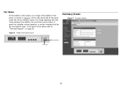
In the event of fan failure refer to start. Figure 6 Switch front panel layout Summary Screen Figure 7 Summary Screen Fan operating Fan failure 22 At the right hand side of the panel under the 3Com company name is an image of the Switch's front panel, as shown in Figure 6. A green fan indicates normal operation, a red fan indicates that the fan has failed to "Technical Support" on page 52. Fan Status At the bottom of all screens is an image depicting two fans. These represent the Switch's fans and their current status.
In the event of fan failure refer to start. Figure 6 Switch front panel layout Summary Screen Figure 7 Summary Screen Fan operating Fan failure 22 At the right hand side of the panel under the 3Com company name is an image of the Switch's front panel, as shown in Figure 6. A green fan indicates normal operation, a red fan indicates that the fan has failed to "Technical Support" on page 52. Fan Status At the bottom of all screens is an image depicting two fans. These represent the Switch's fans and their current status.

User Guide
Page 23
.... 4 Click Apply to save the new password. 23 ■ Management VLAN - IP Settings The IP Settings menu allows you can gain management access to the Switch. Figure 8 Password Screen The password is the only VLAN through which you to the Administration System. Figure 9 IP Settings Screen To change the password to...
.... 4 Click Apply to save the new password. 23 ■ Management VLAN - IP Settings The IP Settings menu allows you can gain management access to the Switch. Figure 8 Password Screen The password is the only VLAN through which you to the Administration System. Figure 9 IP Settings Screen To change the password to...
User Guide
Page 24
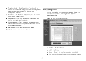
... Port Configuration Screen ■ Number - ■ IP Address Mode - The MAC address of the gateway router between this switch. Number of the default VLAN (VLAN1). ■ Subnet Mask - The IP address of the Switch, and the address of ports. ■ Label - Port Configuration You can use the Basic Port Configuration page to...
... Port Configuration Screen ■ Number - ■ IP Address Mode - The MAC address of the gateway router between this switch. Number of the default VLAN (VLAN1). ■ Subnet Mask - The IP address of the Switch, and the address of ports. ■ Label - Port Configuration You can use the Basic Port Configuration page to...

User Guide
Page 25
... Control - Shows the broadcast storm threshold. (500 - 15000 packets per second) 25 Figure 11 Advanced Port Configuration Screen VLANs The Switch uses VLANs to the originating group and can set the Switch's broadcast storm control and threshold limits. Communication between different VLANs can belong to all connected to a chosen VLAN so that...
... Control - Shows the broadcast storm threshold. (500 - 15000 packets per second) 25 Figure 11 Advanced Port Configuration Screen VLANs The Switch uses VLANs to the originating group and can set the Switch's broadcast storm control and threshold limits. Communication between different VLANs can belong to all connected to a chosen VLAN so that...


