User Guide
Page 3
... SFP Transceivers 18 Inserting an SFP Transceiver 18 Removing an SFP Transceiver 19 Performing Spot Checks 19 3 CONNECTING TO THE WEB INTERFACE Requirements for Accessing the Web Interface 21 Running the Discovery Application 21 Logging On to the Web Interface 22 Navigating Around the Web Interface 23 Menu 23 Buttons 24 Device Mimic 24 Accessing the Interface Without Using Discovery 25 DHCP Assigned IP Address 25 Manually Assigned (Static) IP Address 25 4 CONFIGURING THE SWITCH Configuration Overview 27 Viewing Switch...
... SFP Transceivers 18 Inserting an SFP Transceiver 18 Removing an SFP Transceiver 19 Performing Spot Checks 19 3 CONNECTING TO THE WEB INTERFACE Requirements for Accessing the Web Interface 21 Running the Discovery Application 21 Logging On to the Web Interface 22 Navigating Around the Web Interface 23 Menu 23 Buttons 24 Device Mimic 24 Accessing the Interface Without Using Discovery 25 DHCP Assigned IP Address 25 Manually Assigned (Static) IP Address 25 4 CONFIGURING THE SWITCH Configuration Overview 27 Viewing Switch...

User Guide
Page 4
... Configurations 35 Removing a VLAN 37 Configuring Link Aggregation 37 Guidelines for Creating Aggregated Links 38 Defining the Members of an Aggregated Link 38 Modifying Settings and Deleting an Aggregated Link 39 Viewing the Trunk Summary 39 Viewing Statistics 40 Mirroring Port Traffic 41 Running Cable Diagnostic 42 Using the System Tools 42 Restart 42 Configuration 43 Resetting to Factory Defaults 43 Backing Up and Restoring Configuration 44 Upgrade 44 Spanning Tree 45 802.1p Prioritization 46 Viewing Support Information 47 5 TROUBLESHOOTING Forgotten Password 49 Forgotten Static IP Address...
... Configurations 35 Removing a VLAN 37 Configuring Link Aggregation 37 Guidelines for Creating Aggregated Links 38 Defining the Members of an Aggregated Link 38 Modifying Settings and Deleting an Aggregated Link 39 Viewing the Trunk Summary 39 Viewing Statistics 40 Mirroring Port Traffic 41 Running Cable Diagnostic 42 Using the System Tools 42 Restart 42 Configuration 43 Resetting to Factory Defaults 43 Backing Up and Restoring Configuration 44 Upgrade 44 Spanning Tree 45 802.1p Prioritization 46 Viewing Support Information 47 5 TROUBLESHOOTING Forgotten Password 49 Forgotten Static IP Address...
User Guide
Page 7
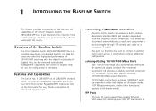
... you to connect network devices to each port using either half-duplex or full-duplex mode. 1000 Mbps connections, on the Switch can therefore be used to connect to know the physical features of the Baseline Switch The 3Com Baseline Switch 2816-SFP/2824-SFP Plus is shipped ready for use configurable Switch. It is necessary. Autosensing of Gigabit links, but do not need sophisticated management capabilities. The 1000BASE-T ports also support automatic 10/100/1000 Mbps speed detection...
... you to connect network devices to each port using either half-duplex or full-duplex mode. 1000 Mbps connections, on the Switch can therefore be used to connect to know the physical features of the Baseline Switch The 3Com Baseline Switch 2816-SFP/2824-SFP Plus is shipped ready for use configurable Switch. It is necessary. Autosensing of Gigabit links, but do not need sophisticated management capabilities. The 1000BASE-T ports also support automatic 10/100/1000 Mbps speed detection...
User Guide
Page 8
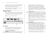
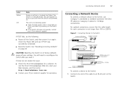
... of using SFP transceivers to numbered sections in operation, the corresponding 10/100/1000BASE-T port is disabled. Physical Features Figure 1 shows the front and rear panels of various networking and connection operations. (1) RJ-45 10/100/1000 Ports WARNING: RJ-45 Ports. Figure 1 Front and Rear Panels (2816-SFP) 1 1 9 8 4 5 12 13 Baseline Switch 2816-SFP Plus Module Present 8 16 Link/Activity : Green = 1000M, Yellow = 10/1000M, Flash = Activity, Duplex...
... of using SFP transceivers to numbered sections in operation, the corresponding 10/100/1000BASE-T port is disabled. Physical Features Figure 1 shows the front and rear panels of various networking and connection operations. (1) RJ-45 10/100/1000 Ports WARNING: RJ-45 Ports. Figure 1 Front and Rear Panels (2816-SFP) 1 1 9 8 4 5 12 13 Baseline Switch 2816-SFP Plus Module Present 8 16 Link/Activity : Green = 1000M, Yellow = 10/1000M, Flash = Activity, Duplex...
User Guide
Page 16
... free from lightning and power surges. Ensure that POST failed and the Switch has entered fail-safe mode. When the Switch is connected to earth ground during normal use Supplying Power to the Switch Power problems can be grounded. During POST, the Power LED on and power off the Switch is called "power cycling". CAUTION: The Switch has no ON/OFF switch. Table 5Table 5 summarizes the possible colors for use . 16 CHAPTER 2: INSTALLING THE SWITCH...
... free from lightning and power surges. Ensure that POST failed and the Switch has entered fail-safe mode. When the Switch is connected to earth ground during normal use Supplying Power to the Switch Power problems can be grounded. During POST, the Power LED on and power off the Switch is called "power cycling". CAUTION: The Switch has no ON/OFF switch. Table 5Table 5 summarizes the possible colors for use . 16 CHAPTER 2: INSTALLING THE SWITCH...
User Guide
Page 17
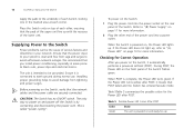
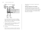
... Switch Baseline 10/100 Switch Endstations on switched 100 Mbps connections Baseline 10/100 Switch Endstations on switched 100 Mbps connections BaselineBSawsietclihne28S1w6i/t2ch82242-5S0FP Plus 1000 Mbps copper or F iber connection to backbone or server/worksation 1000 Mbps link 10 Mbps or 100 Mbps link Endstations on switched 100 Mbps or 1000 Mbps connections To connect a device to the Switch: 1 Connect one end of the cable to Factory Defaults" on the Switch. Check the Power LED...
... Switch Baseline 10/100 Switch Endstations on switched 100 Mbps connections Baseline 10/100 Switch Endstations on switched 100 Mbps connections BaselineBSawsietclihne28S1w6i/t2ch82242-5S0FP Plus 1000 Mbps copper or F iber connection to backbone or server/worksation 1000 Mbps link 10 Mbps or 100 Mbps link Endstations on switched 100 Mbps or 1000 Mbps connections To connect a device to the Switch: 1 Connect one end of the cable to Factory Defaults" on the Switch. Check the Power LED...

User Guide
Page 25
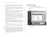
... Switch, and then use that IP address to access the Web interface. ■ Enable or disable flow control ■ Configure the speed duplex settings ■ Set traffic priority for the IP address that is assigned to the Switch, and then using that the Switch will perform auto IP configuration to assign an IP address to itself during auto IP configuration, check the sticker on page 29. Accessing the Interface Without Using Discovery 25 For example, if the DHCP server assigned the IP address...
... Switch, and then use that IP address to access the Web interface. ■ Enable or disable flow control ■ Configure the speed duplex settings ■ Set traffic priority for the IP address that is assigned to the Switch, and then using that the Switch will perform auto IP configuration to assign an IP address to itself during auto IP configuration, check the sticker on page 29. Accessing the Interface Without Using Discovery 25 For example, if the DHCP server assigned the IP address...
User Guide
Page 27
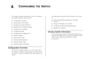
...; Configuration Overview ■ Viewing Switch Information ■ Changing the Admin Password ■ Modifying the IP Address Settings ■ Configuring Port Settings ■ Configuring VLANs ■ Configuring Link Aggregation ■ Viewing Statistics ■ Mirroring Port Traffic ■ Running Cable Diagnostic ■ Using the System Tools ■ Viewing Support Information Configuration Overview The Switch is shipped ready for use. You only need to access the Web interface if you want the Switch to function as a basic layer 2 switch, you log on how to configure the Switch...
...; Configuration Overview ■ Viewing Switch Information ■ Changing the Admin Password ■ Modifying the IP Address Settings ■ Configuring Port Settings ■ Configuring VLANs ■ Configuring Link Aggregation ■ Viewing Statistics ■ Mirroring Port Traffic ■ Running Cable Diagnostic ■ Using the System Tools ■ Viewing Support Information Configuration Overview The Switch is shipped ready for use. You only need to access the Web interface if you want the Switch to function as a basic layer 2 switch, you log on how to configure the Switch...
User Guide
Page 28
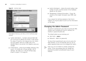
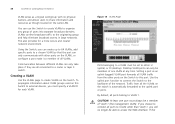
... page. The default admin account settings are: ■ User name - If you request for technical assistance from accessing the Web interface and modifying the Switch's settings, the interface is password-protected. Contains optional fields that you set an admin password when you first configure the Switch. After you update any of the editable fields in Figure 11 on the Switch ■ Management Software Information - Changing the Admin Password To prevent unauthorized users from 3Com Support, you...
... page. The default admin account settings are: ■ User name - If you request for technical assistance from accessing the Web interface and modifying the Switch's settings, the interface is password-protected. Contains optional fields that you set an admin password when you first configure the Switch. After you update any of the editable fields in Figure 11 on the Switch ■ Management Software Information - Changing the Admin Password To prevent unauthorized users from 3Com Support, you...

User Guide
Page 29
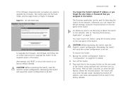
... Switch does not have not previously set it, refer to "Forgotten Password" on page 48 for information on the Switch for the Discovery application to be able to connect to itself during auto IP configuration, check the If you power on how to regain access to it automatically uses the default IP address 169.254.x.y, where x and y are the last two bytes of its MAC address...
... Switch does not have not previously set it, refer to "Forgotten Password" on page 48 for information on the Switch for the Discovery application to be able to connect to itself during auto IP configuration, check the If you power on how to regain access to it automatically uses the default IP address 169.254.x.y, where x and y are the last two bytes of its MAC address...
User Guide
Page 30
.... 3Com recommends using DHCP or assigning a static IP address) to generate its MAC address. The IP address would be 169.254.1.2. Once you gain access to the console, you should assign an IP address to the Switch (either by one to ensure successful communication between the Switch and other switches on the network have this IP address. The IP Settings page appears. This sticker contains the MAC address and default...
.... 3Com recommends using DHCP or assigning a static IP address) to generate its MAC address. The IP address would be 169.254.1.2. Once you gain access to the console, you should assign an IP address to the Switch (either by one to ensure successful communication between the Switch and other switches on the network have this IP address. The IP Settings page appears. This sticker contains the MAC address and default...

User Guide
Page 31
... Address Mode is set to Static. Configuring Port Settings Using the Web interface, you want to assign to the Switch. The IP address that belongs to VLAN 1. The default subnet mask is assigned to the Switch also becomes the IP address for VLAN 1. You can configure the speed/duplex and flow control settings of each port. By default, all ports belong to Static. Select this option if you have a DHCP server on the network and you can also view the current connection status...
... Address Mode is set to Static. Configuring Port Settings Using the Web interface, you want to assign to the Switch. The IP address that belongs to VLAN 1. The default subnet mask is assigned to the Switch also becomes the IP address for VLAN 1. You can configure the speed/duplex and flow control settings of each port. By default, all ports belong to Static. Select this option if you have a DHCP server on the network and you can also view the current connection status...
User Guide
Page 34
... can create up to 64 VLANs, add specific ports to a chosen VLAN (so that the port can only take place if they are all ports belong to a router or layer 3 switch. CAUTION: At least one VLAN at any group of one port must be set to access the Web interface. Use the uplink port function to connect the Switch to the originating group and help eliminate broadcast storms in large networks. 34 CHAPTER 4: CONFIGURING THE SWITCH VLAN...
... can create up to 64 VLANs, add specific ports to a chosen VLAN (so that the port can only take place if they are all ports belong to a router or layer 3 switch. CAUTION: At least one VLAN at any group of one port must be set to access the Web interface. Use the uplink port function to connect the Switch to the originating group and help eliminate broadcast storms in large networks. 34 CHAPTER 4: CONFIGURING THE SWITCH VLAN...

User Guide
Page 35
... how you can segment network devices that you will need to reset the Switch to "Sample VLAN Configurations" on the Switch using desktop connections. 4 Define the VLAN membership by setting the state of each port. The VLANs page appears. 2 In VLAN ID, click Create New VLAN. 3 In VLAN ID (1-4094), type an unused ID number for the VLAN that are connected to create the VLAN. For examples on setting up a simple VLAN on page 35.
... how you can segment network devices that you will need to reset the Switch to "Sample VLAN Configurations" on the Switch using desktop connections. 4 Define the VLAN membership by setting the state of each port. The VLANs page appears. 2 In VLAN ID, click Create New VLAN. 3 In VLAN ID (1-4094), type an unused ID number for the VLAN that are connected to create the VLAN. For examples on setting up a simple VLAN on page 35.
User Guide
Page 36
...: 1 Create a new VLAN and set the VLAN ID to the VLAN or change the port configuration. Refer to D (desktop egress packet). 3 Click Apply. VLAN1 is set up a VLAN across two Switches using uplink connections. This enables ports that are members of the same VLAN (but are connected. Server Server in VLAN 1 in VLAN 2 If you want to add ports 7, 8, and 16 to VLAN2 (as shown in VLAN 2 Baseline Switch 2824-SFP Plus add another port to 2. 36 CHAPTER 4: CONFIGURING THE SWITCH Figure 16 Desktop VLAN Configuration Endstations in VLAN...
...: 1 Create a new VLAN and set the VLAN ID to the VLAN or change the port configuration. Refer to D (desktop egress packet). 3 Click Apply. VLAN1 is set up a VLAN across two Switches using uplink connections. This enables ports that are members of the same VLAN (but are connected. Server Server in VLAN 1 in VLAN 2 If you want to add ports 7, 8, and 16 to VLAN2 (as shown in VLAN 2 Baseline Switch 2824-SFP Plus add another port to 2. 36 CHAPTER 4: CONFIGURING THE SWITCH Figure 16 Desktop VLAN Configuration Endstations in VLAN...

User Guide
Page 37
... Switch 2 (in this example, port 8). Configuring Link Aggregation 37 2 On Switch 1, set the ports that are members of VLAN2 can be part of a network connection and ensures fault recovery. You need not create VLAN1 since it . Set one port (for example, port 8) to delete. 2 Click Remove. Set one port (for example, port 16) to be statically grouped into an aggregated link, also known as a "trunk". Configuring Link Aggregation Ports can now communicate with those ports on Switch 2 that you want to D (desktop egress packet). The VLANs...
... Switch 2 (in this example, port 8). Configuring Link Aggregation 37 2 On Switch 1, set the ports that are members of VLAN2 can be part of a network connection and ensures fault recovery. You need not create VLAN1 since it . Set one port (for example, port 8) to delete. 2 Click Remove. Set one port (for example, port 16) to be statically grouped into an aggregated link, also known as a "trunk". Configuring Link Aggregation Ports can now communicate with those ports on Switch 2 that you want to D (desktop egress packet). The VLANs...

User Guide
Page 46
... as switches, that time-sensitive traffic gets the highest level of traffic may require priority over that are part of traffic. If the Switch is forwarded through the normal or high priority channel. This ensures that are present in the hardware of which means all other ports. The 802.1D standard specifies eight distinct levels of priority (0 to a particular type of the spanning tree network, set...
... as switches, that time-sensitive traffic gets the highest level of traffic may require priority over that are part of traffic. If the Switch is forwarded through the normal or high priority channel. This ensures that are present in the hardware of which means all other ports. The 802.1D standard specifies eight distinct levels of priority (0 to a particular type of the spanning tree network, set...

User Guide
Page 49
... Factory Defaults" on page 43 for instructions. See "Resetting to "Running the Discovery Application" on page 21. For information on using the default admin account settings: ■ User name - After resetting the Switch, log on to Appendix A. For information on basic LED checks, refer to the following topics in Chapter 1: ■ (3) Link/Activity Status LEDs ■ (4) Module Active LEDs ■ (5) Port Duplex LEDs ■ (6) Power LED A link is connected but the Link/Activity Status LED for your local technical support representative. 5 TROUBLESHOOTING...
... Factory Defaults" on page 43 for instructions. See "Resetting to "Running the Discovery Application" on page 21. For information on using the default admin account settings: ■ User name - After resetting the Switch, log on to Appendix A. For information on basic LED checks, refer to the following topics in Chapter 1: ■ (3) Link/Activity Status LEDs ■ (4) Module Active LEDs ■ (5) Port Duplex LEDs ■ (6) Power LED A link is connected but the Link/Activity Status LED for your local technical support representative. 5 TROUBLESHOOTING...
User Guide
Page 51
... the Switch. Solving LED Issues 51 You forget the Switch's default IP address, or you forget the User Name or Password that you need to upgrade the firmware. The Discovery application can restore the default settings, using the recovery button on the Switch. Recovering the Switch will cause the current configuration to be reset to its factory default settings. The Switch will now enter fail safe mode, whereby the Switch's IP address, user name and password will be lost . The Switch...
... the Switch. Solving LED Issues 51 You forget the Switch's default IP address, or you forget the User Name or Password that you need to upgrade the firmware. The Discovery application can restore the default settings, using the recovery button on the Switch. Recovering the Switch will cause the current configuration to be reset to its factory default settings. The Switch will now enter fail safe mode, whereby the Switch's IP address, user name and password will be lost . The Switch...
User Guide
Page 54
... repair services. To access these services for a user name and password. Telephone Technical Support and Repair To obtain telephone support as part of the warranty and other service benefits start from the date of system hardware and software, including revision level ■ Diagnostic error messages ■ Details about recent configuration changes, if applicable To send a product directly to software downloads can obtain an RMA number online at http://eSupport.3com.com...
... repair services. To access these services for a user name and password. Telephone Technical Support and Repair To obtain telephone support as part of the warranty and other service benefits start from the date of system hardware and software, including revision level ■ Diagnostic error messages ■ Details about recent configuration changes, if applicable To send a product directly to software downloads can obtain an RMA number online at http://eSupport.3com.com...


