Installation Guide
Page 2
...Chapter 2 Smart Interface Cards (Router 5000 2-1 2.1 ROUTER 1-PORT 10/100 SIC 2-1 2.1.1 Interface Attributes 2-1 2.1.2 Interface Cable ...2-2 2.1.3 Connecting the Interface Cable 2-2 2.2 ROUTER 1-PORT SERIAL SIC 2-3 2.2.1 Introduction...2-3 2.2.2 Appearance ...2-4 2.2.3 Interface Attributes 2-5 2.2.4 Interface LEDs...2-6 2.2.5 Interface Cable ...2-6 2.2.6 Connecting Interface Cable 2-8 2.3 ROUTER 2-PORT ISDN-S/T SIC and ROUTER 2-PORT ISDN-U SIC 2-9 2.3.1 Introduction...2-9 2.3.2 Appearance ...2-9 2.3.3 Interface Attributes 2-10 2.3.4 Interface LEDs...2-10 2.3.5 Interface Cable ...2-11...
...Chapter 2 Smart Interface Cards (Router 5000 2-1 2.1 ROUTER 1-PORT 10/100 SIC 2-1 2.1.1 Interface Attributes 2-1 2.1.2 Interface Cable ...2-2 2.1.3 Connecting the Interface Cable 2-2 2.2 ROUTER 1-PORT SERIAL SIC 2-3 2.2.1 Introduction...2-3 2.2.2 Appearance ...2-4 2.2.3 Interface Attributes 2-5 2.2.4 Interface LEDs...2-6 2.2.5 Interface Cable ...2-6 2.2.6 Connecting Interface Cable 2-8 2.3 ROUTER 2-PORT ISDN-S/T SIC and ROUTER 2-PORT ISDN-U SIC 2-9 2.3.1 Introduction...2-9 2.3.2 Appearance ...2-9 2.3.3 Interface Attributes 2-10 2.3.4 Interface LEDs...2-10 2.3.5 Interface Cable ...2-11...
Installation Guide
Page 4
... 3.6.2 Interface Attributes 3-22 3.6.3 Interface LEDs...3-23 3.6.4 Interface Cable ...3-23 3.6.5 Connecting the Interface Cable 3-24 3.7 ROUTER 2 AND 4-PORT ENHANCED SERIAL MIM 3-25 3.7.1 Introduction...3-25 3.7.2 Interface Attributes 3-26 3.7.3 Interface LEDs...3-27 3.7.4 Interface Cable ...3-28 3.7.5 Connecting the Interface Cable 3-31 3.8 Router 2 and 4-Port CE1/PRI MIM Modules 3-32 3.8.1 Introduction...3-32 3.8.2 Interface Attributes 3-32 3.8.3 Interface LEDs...3-33 3.8.4 Interface Cable ...3-34 3.8.5 Internal DIP Switches 3-37 3.8.6 Connecting the Interface Cable 3-38 3.9 Router...
... 3.6.2 Interface Attributes 3-22 3.6.3 Interface LEDs...3-23 3.6.4 Interface Cable ...3-23 3.6.5 Connecting the Interface Cable 3-24 3.7 ROUTER 2 AND 4-PORT ENHANCED SERIAL MIM 3-25 3.7.1 Introduction...3-25 3.7.2 Interface Attributes 3-26 3.7.3 Interface LEDs...3-27 3.7.4 Interface Cable ...3-28 3.7.5 Connecting the Interface Cable 3-31 3.8 Router 2 and 4-Port CE1/PRI MIM Modules 3-32 3.8.1 Introduction...3-32 3.8.2 Interface Attributes 3-32 3.8.3 Interface LEDs...3-33 3.8.4 Interface Cable ...3-34 3.8.5 Internal DIP Switches 3-37 3.8.6 Connecting the Interface Cable 3-38 3.9 Router...
Installation Guide
Page 6
... 10/100/1000 MIM 3-64 3.18.1 Introduction...3-64 3.18.2 Interface Attributes 3-64 3.18.3 Interface Cable ...3-65 3.18.4 Connecting the Interface Cable 3-65 Chapter 4 Flexible Interface Cards (Router 6000 3-65 4.1.1 Router 2-Port 10/100 FIC 3-65 4.1.2 Introduction...3-65 4.1.3 Interface Attributes 3-65 4.1.4 Panel and Interface LEDs 3-65 4.1.5 Interface Cable ...3-65 4.1.6 Connecting the Interface Cable 3-65 4.1.7 Router 1-Port 100FX MM FIC/100FX SM FIC 3-65 4.1.8 Introduction...
... 10/100/1000 MIM 3-64 3.18.1 Introduction...3-64 3.18.2 Interface Attributes 3-64 3.18.3 Interface Cable ...3-65 3.18.4 Connecting the Interface Cable 3-65 Chapter 4 Flexible Interface Cards (Router 6000 3-65 4.1.1 Router 2-Port 10/100 FIC 3-65 4.1.2 Introduction...3-65 4.1.3 Interface Attributes 3-65 4.1.4 Panel and Interface LEDs 3-65 4.1.5 Interface Cable ...3-65 4.1.6 Connecting the Interface Cable 3-65 4.1.7 Router 1-Port 100FX MM FIC/100FX SM FIC 3-65 4.1.8 Introduction...
Installation Guide
Page 12
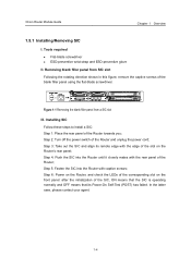
... the power cord; Step 4: Push the SIC into the Router with the rear panel of the Router; 3Com Router Module Guide Chapter 1 Overview 1.5.1 Installing/Removing SIC I. Tools required z Flat-blade screwdriver z ESD-preventive wrist strap and ESD-preventive glove II. Step 2: Turn off the power switch of the blank filler panel using the flat-blade...
... the power cord; Step 4: Push the SIC into the Router with the rear panel of the Router; 3Com Router Module Guide Chapter 1 Overview 1.5.1 Installing/Removing SIC I. Tools required z Flat-blade screwdriver z ESD-preventive wrist strap and ESD-preventive glove II. Step 2: Turn off the power switch of the blank filler panel using the flat-blade...
Installation Guide
Page 13
... Router and unplug the power cord; 3Com Router Module Guide Chapter 1 Overview Figure 1-2 Installing SIC IV. Step 3: Unplug all the network interface cables connected to install a MIM: Step 1: Place the rear panel of the Router; Removing SIC Follow these steps to the rear panel of the Router towards you ; Step 2: Turn off the power switch of the Router...
... Router and unplug the power cord; 3Com Router Module Guide Chapter 1 Overview Figure 1-2 Installing SIC IV. Step 3: Unplug all the network interface cables connected to install a MIM: Step 1: Place the rear panel of the Router; Removing SIC Follow these steps to the rear panel of the Router towards you ; Step 2: Turn off the power switch of the Router...

Installation Guide
Page 14
Step 3: Unplug all interface cables from the bottom of the router. 1.6 Troubleshooting 3Com 5000 Routers LEDs, indicate the state of the module as follows: After the installation of a SIC/MIM, turn on the power and view the corresponding LEDs (such as SLOT0, SLOT1 or SLOT2) on the cover of the Router chassis: ON means... that the SIC/MIM is completely separated from the rear panel of the Router; Step 2: Turn off the power switch of the MIM; Step 4: Loosen the captive screws at both sides of the Router and unplug the power cord; Step 5: Pull the MIM towards you until it is ...
Step 3: Unplug all interface cables from the bottom of the router. 1.6 Troubleshooting 3Com 5000 Routers LEDs, indicate the state of the module as follows: After the installation of a SIC/MIM, turn on the power and view the corresponding LEDs (such as SLOT0, SLOT1 or SLOT2) on the cover of the Router chassis: ON means... that the SIC/MIM is completely separated from the rear panel of the Router; Step 2: Turn off the power switch of the MIM; Step 4: Loosen the captive screws at both sides of the Router and unplug the power cord; Step 5: Pull the MIM towards you until it is ...
Installation Guide
Page 17
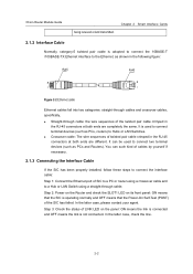
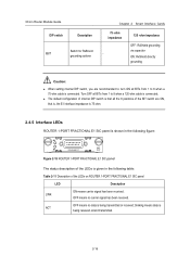
... the SIC has failed. You can be used to connect terminal devices (such as PCs, routers) to Hubs or LAN Switches. In the latter case, please contact your agent. Chapter 2 Smart Interface Cards 2.1.2 Interface Cable Normally, category-5 twisted pair cable is not connected. It can such kind of cables ...cable; Step 3: Check the status of the twisted pair cable crimped in the RJ-45 connectors at both ends are completely the same. 3Com Router Module Guide being received or/and transmitted. It is operating normally and OFF means that the Power-On Self-Test (POST) of twisted...
... the SIC has failed. You can be used to connect terminal devices (such as PCs, routers) to Hubs or LAN Switches. In the latter case, please contact your agent. Chapter 2 Smart Interface Cards 2.1.2 Interface Cable Normally, category-5 twisted pair cable is not connected. It can such kind of cables ...cable; Step 3: Check the status of the twisted pair cable crimped in the RJ-45 connectors at both ends are completely the same. 3Com Router Module Guide being received or/and transmitted. It is operating normally and OFF means that the Power-On Self-Test (POST) of twisted...
Installation Guide
Page 19
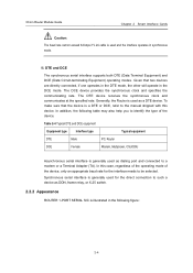
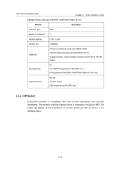
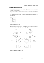
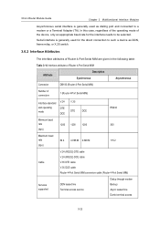
... mode. In addition, the following figure: 2-4 Synchronous serial interface is generally used as DDN, frame relay, or X.25 switch. 2.2.2 Appearance ROUTER 1-PORT SERIAL SIC is illustrated in the following table may also...Interface type Typical equipment DTE Male PC, Router DCE Female Modem, Multiplexer, CSU/DSU Asynchronous serial interface is generally used for the interface needs to a modem or a Terminal Adapter (TA). Generally, the Router is used and the interface operates in the DCE mode. 3Com Router Module Guide Chapter 2 Smart Interface Cards...
... mode. In addition, the following figure: 2-4 Synchronous serial interface is generally used as DDN, frame relay, or X.25 switch. 2.2.2 Appearance ROUTER 1-PORT SERIAL SIC is illustrated in the following table may also...Interface type Typical equipment DTE Male PC, Router DCE Female Modem, Multiplexer, CSU/DSU Asynchronous serial interface is generally used for the interface needs to a modem or a Terminal Adapter (TA). Generally, the Router is used and the interface operates in the DCE mode. 3Com Router Module Guide Chapter 2 Smart Interface Cards...
Installation Guide
Page 29
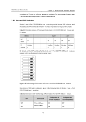
... of impedance through an 8BIT DIP switch. The interface matches different types of the DIP switch are ON, as shown in the following figure: 2-14 3Com Router Module Guide Chapter 2 Smart Interface Cards Table 2-9 Interface attributes of ROUTER 1-PORT FRACTIONAL E1 SIC Attribute Description Connector type DB15 Number of connectors 1 Interface standard G.703, G.704 Interface rate 2.048Mbps Cable type 75-ohm...
... of impedance through an 8BIT DIP switch. The interface matches different types of the DIP switch are ON, as shown in the following figure: 2-14 3Com Router Module Guide Chapter 2 Smart Interface Cards Table 2-9 Interface attributes of ROUTER 1-PORT FRACTIONAL E1 SIC Attribute Description Connector type DB15 Number of connectors 1 Interface standard G.703, G.704 Interface rate 2.048Mbps Cable type 75-ohm...
Installation Guide
Page 30
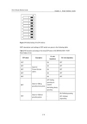
... ON: RxShield grounding OFF: RxShield ungrounding 2-15 grounding mode options ON: RxRing directly grounding Switch for RxRing capacitor - 3Com Router Module Guide on 1 2 3 4 5 6 7 8 Chapter 2 Smart Interface Cards Figure 2-14 Default setting of the DIP switches 8BIT description and settings of DIP switch are given in the following table: Table 2-10 Description and settings of the internal DIP...
... ON: RxShield grounding OFF: RxShield ungrounding 2-15 grounding mode options ON: RxRing directly grounding Switch for RxRing capacitor - 3Com Router Module Guide on 1 2 3 4 5 6 7 8 Chapter 2 Smart Interface Cards Figure 2-14 Default setting of the DIP switches 8BIT description and settings of DIP switch are given in the following table: Table 2-10 Description and settings of the internal DIP...
Installation Guide
Page 31
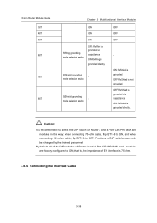
... been received. z The default configuration of internal DIP switch is that all the 8 positions of the BIT switch are recommended to: turn ON all BITs from 1 to 8 when a 75-ohm cable is connected. 3Com Router Module Guide DIP switch Description Switch for RxShield 8BIT grounding options Chapter 2 Smart Interface Cards 75 -ohm impedance - 120 -ohm impedance OFF: RxShield...
... been received. z The default configuration of internal DIP switch is that all the 8 positions of the BIT switch are recommended to: turn ON all BITs from 1 to 8 when a 75-ohm cable is connected. 3Com Router Module Guide DIP switch Description Switch for RxShield 8BIT grounding options Chapter 2 Smart Interface Cards 75 -ohm impedance - 120 -ohm impedance OFF: RxShield...
Installation Guide
Page 33
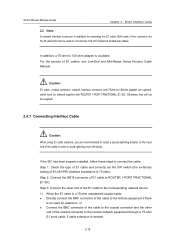
...-120ohm adapter are RJ-45 jacks that can be used to connect two 120-ohm balanced twisted pair cables. 3Com Router Module Guide Chapter 2 Smart Interface Cards Note: A network interface connector is available for extension, or z Connect the BNC connector of the cable to the coaxial connector and ...connect the cable: Step 1: Check the type of E1 cable and correctly set the DIP switch (the ex-factory setting of the connector are optional, which must be supplied. 2.4.7 Connecting Interface Cable Caution: When using E1 cable outdoors, you are recommended to install a special lightning ...
...-120ohm adapter are RJ-45 jacks that can be used to connect two 120-ohm balanced twisted pair cables. 3Com Router Module Guide Chapter 2 Smart Interface Cards Note: A network interface connector is available for extension, or z Connect the BNC connector of the cable to the coaxial connector and ...connect the cable: Step 1: Check the type of E1 cable and correctly set the DIP switch (the ex-factory setting of the connector are optional, which must be supplied. 2.4.7 Connecting Interface Cable Caution: When using E1 cable outdoors, you are recommended to install a special lightning ...
Installation Guide
Page 49
...of RJ-45 pins When connection is shown in the following figure, numbered 1 to 8 from left to communicate with the Router in the following figure: PBX E detect 7 M on-hook Router on-hook off-hook -48 V off-hook M on-hook T0 2 E T0 6 detect -48 V -48 V... of 3Com 5000 Family Routers support Bell I, II, III, V switches, and 2-wire & 4-wire voice signals. wire voice signal R1 R1 4 Figure 3-10 E&M interface cable (Bell V 4-wire) 3-5 Interface cable of E&M modules E&M modules of RJ-45 receptacles at router side and at the switch side are shown in practice. 3Com Router Module ...
...of RJ-45 pins When connection is shown in the following figure, numbered 1 to 8 from left to communicate with the Router in the following figure: PBX E detect 7 M on-hook Router on-hook off-hook -48 V off-hook M on-hook T0 2 E T0 6 detect -48 V -48 V... of 3Com 5000 Family Routers support Bell I, II, III, V switches, and 2-wire & 4-wire voice signals. wire voice signal R1 R1 4 Figure 3-10 E&M interface cable (Bell V 4-wire) 3-5 Interface cable of E&M modules E&M modules of RJ-45 receptacles at router side and at the switch side are shown in practice. 3Com Router Module ...
Installation Guide
Page 50
3Com Router Module Guide Chapter 3 Multifunctional Interface Modules Table 3-3 Pinouts of the prepared E&M module interface cable by the user. To ensure the EMC of the Router, install a ferrite core near the connector of E&M interface cable (Bell V 4-wire) RJ-45 Pin Router side RJ-45 interface signal ...of the switch to be prepared according to the on-spot conditions or by the router side. 3.1.6 Connecting Interface Cable 3-6 To ensure EMC of Router 2 and 4-Port E&M/E&M modules have to the Router. ground) Note: z Interface cables of Router 2-Port FXS/FXO and Router 4-Port FXS...
3Com Router Module Guide Chapter 3 Multifunctional Interface Modules Table 3-3 Pinouts of the prepared E&M module interface cable by the user. To ensure the EMC of the Router, install a ferrite core near the connector of E&M interface cable (Bell V 4-wire) RJ-45 Pin Router side RJ-45 interface signal ...of the switch to be prepared according to the on-spot conditions or by the router side. 3.1.6 Connecting Interface Cable 3-6 To ensure EMC of Router 2 and 4-Port E&M/E&M modules have to the Router. ground) Note: z Interface cables of Router 2-Port FXS/FXO and Router 4-Port FXS...
Installation Guide
Page 51
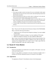
... practice, the PGND wire of the switch can handle dense voice signals in VoIP system. z Subscriber line of telephone exchange, if you have installed an FXS module; Router E1 Voice Module is shown in the form of board plus daughter card. z Read the mark identifying a...do not provide PGND wire. Wrong connection tends to damage interface modules and even the Router. z As provisioned by Bell V, cables for it will blink once, meaning it is the correct port. 3Com Router Module Guide Chapter 3 Multifunctional Interface Modules Caution: z Some measures are recommended to install a...
... practice, the PGND wire of the switch can handle dense voice signals in VoIP system. z Subscriber line of telephone exchange, if you have installed an FXS module; Router E1 Voice Module is shown in the form of board plus daughter card. z Read the mark identifying a...do not provide PGND wire. Wrong connection tends to damage interface modules and even the Router. z As provisioned by Bell V, cables for it will blink once, meaning it is the correct port. 3Com Router Module Guide Chapter 3 Multifunctional Interface Modules Caution: z Some measures are recommended to install a...
Installation Guide
Page 64
... cause damages to the interface card and even the device. 3.6 Router 4-Port Serial MIM Module 3.6.1 Introduction 4-port high-speed sync/async serial interface module (Router 4-Port Serial MIM) supports both synchronous and asynchronous modes to a HUB or LAN switch. Caution: Before you ... HUB or LAN switch, use a straight-through cables. Synchronous and asynchronous In different operating modes, a sync/async serial interface supports different signal standards and baud rates. 3Com Router Module Guide Chapter 3 Multifunctional Interface Modules example, PC or router) to transmit/receive...
... cause damages to the interface card and even the device. 3.6 Router 4-Port Serial MIM Module 3.6.1 Introduction 4-port high-speed sync/async serial interface module (Router 4-Port Serial MIM) supports both synchronous and asynchronous modes to a HUB or LAN switch. Caution: Before you ... HUB or LAN switch, use a straight-through cables. Synchronous and asynchronous In different operating modes, a sync/async serial interface supports different signal standards and baud rates. 3Com Router Module Guide Chapter 3 Multifunctional Interface Modules example, PC or router) to transmit/receive...
Installation Guide
Page 66
... as dialing port and connected to be selected. 3Com Router Module Guide Chapter 3 Multifunctional Interface Modules Asynchronous serial interface is generally used as DDN, frame relay, or X.25 switch. 3.6.2 Interface Attributes The interface attributes of Router 4-Port Serial MIM are given in the following table: Table 3-14 Interface attributes of Router 4-Port Serial MIM Attribute Description Synchronous Asynchronous Connector DB100...
... as dialing port and connected to be selected. 3Com Router Module Guide Chapter 3 Multifunctional Interface Modules Asynchronous serial interface is generally used as DDN, frame relay, or X.25 switch. 3.6.2 Interface Attributes The interface attributes of Router 4-Port Serial MIM are given in the following table: Table 3-14 Interface attributes of Router 4-Port Serial MIM Attribute Description Synchronous Asynchronous Connector DB100...
Installation Guide
Page 81
For the pinouts of cables, see Low-End and Mid-Range Series Routers Cable Manual. 3.8.5 Internal DIP Switches Router 2 and 4-Port CE1/PRI MIM and modules provide internal DIP switches, and the setting of DIP switch settings is provided. 3Com Router Module Guide Chapter 3 Multifunctional Interface Modules In addition, a 75-ohm to ON, as illustrated in the following figure...
For the pinouts of cables, see Low-End and Mid-Range Series Routers Cable Manual. 3.8.5 Internal DIP Switches Router 2 and 4-Port CE1/PRI MIM and modules provide internal DIP switches, and the setting of DIP switch settings is provided. 3Com Router Module Guide Chapter 3 Multifunctional Interface Modules In addition, a 75-ohm to ON, as illustrated in the following figure...
Installation Guide
Page 82
... - ON: RxShield is grounded. Caution: It is recommended to OFF. Positions of DIP switches can only be changed by the trained personnel. 3Com Router Module Guide 3BIT 4BIT 5BIT 6BIT 7BIT 8BIT Chapter 3 Multifunctional Interface Modules ON ON ON RxRing grounding mode selection switch OFF: RxRing is grounded via capacitance ON: RxShield is grounded directly.
... - ON: RxShield is grounded. Caution: It is recommended to OFF. Positions of DIP switches can only be changed by the trained personnel. 3Com Router Module Guide 3BIT 4BIT 5BIT 6BIT 7BIT 8BIT Chapter 3 Multifunctional Interface Modules ON ON ON RxRing grounding mode selection switch OFF: RxRing is grounded via capacitance ON: RxShield is grounded directly.
Installation Guide
Page 83
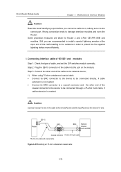
3Com Router Module Guide Chapter 3 Multifunctional Interface Modules Caution: Read the mark identifying a port before you are taken for Router 2 and 4-Port CE1/PRI MIM and modules. z Connect its BNC connector to the device to it, making sure it is needed ; Connecting interface cable of 1E1/2E1 and modules Step 1:... directly, if cable extension is not needed ; Step 3: Connect the other end of cable, and set the DIP switches module correctly; DB -15 BNC Router BNC Network devices such as DDN Coaxial connector 75-ohm E1 trunk cable 75-ohm non-balanced coaxial cable Figure 3-45...
3Com Router Module Guide Chapter 3 Multifunctional Interface Modules Caution: Read the mark identifying a port before you are taken for Router 2 and 4-Port CE1/PRI MIM and modules. z Connect its BNC connector to the device to it, making sure it is needed ; Connecting interface cable of 1E1/2E1 and modules Step 1:... directly, if cable extension is not needed ; Step 3: Connect the other end of cable, and set the DIP switches module correctly; DB -15 BNC Router BNC Network devices such as DDN Coaxial connector 75-ohm E1 trunk cable 75-ohm non-balanced coaxial cable Figure 3-45...