Installation Guide
Page 2
...Chapter 2 Smart Interface Cards (Router 5000 2-1 2.1 ROUTER 1-PORT 10/100 SIC 2-1 2.1.1 Interface Attributes 2-1 2.1.2 Interface Cable ...2-2 2.1.3 Connecting the Interface Cable 2-2 2.2 ROUTER 1-PORT SERIAL SIC 2-3 2.2.1 Introduction...2-3 2.2.2 Appearance ...2-4 2.2.3 Interface Attributes 2-5 2.2.4 Interface LEDs...2-6 2.2.5 Interface Cable ...2-6 2.2.6 Connecting Interface Cable 2-8 2.3 ROUTER 2-PORT ISDN-S/T SIC and ROUTER 2-PORT ISDN-U SIC 2-9 2.3.1 Introduction...2-9 2.3.2 Appearance ...2-9 2.3.3 Interface Attributes 2-10 2.3.4 Interface LEDs...2-10 2.3.5 Interface Cable ...2-11...
...Chapter 2 Smart Interface Cards (Router 5000 2-1 2.1 ROUTER 1-PORT 10/100 SIC 2-1 2.1.1 Interface Attributes 2-1 2.1.2 Interface Cable ...2-2 2.1.3 Connecting the Interface Cable 2-2 2.2 ROUTER 1-PORT SERIAL SIC 2-3 2.2.1 Introduction...2-3 2.2.2 Appearance ...2-4 2.2.3 Interface Attributes 2-5 2.2.4 Interface LEDs...2-6 2.2.5 Interface Cable ...2-6 2.2.6 Connecting Interface Cable 2-8 2.3 ROUTER 2-PORT ISDN-S/T SIC and ROUTER 2-PORT ISDN-U SIC 2-9 2.3.1 Introduction...2-9 2.3.2 Appearance ...2-9 2.3.3 Interface Attributes 2-10 2.3.4 Interface LEDs...2-10 2.3.5 Interface Cable ...2-11...
Installation Guide
Page 3
...28 2.7.6 Connecting Interface Cable 2-29 Chapter 3 Multifunctional Interface Modules (Router 5000 3-1 3.1 Router 2-Port FXS/FXO/E&M MIM Modules & Router 4-Port 4FXS/4FXO/4E&M MIM Modules ...3-1 3.1.1 Introduction...3-1 3.1.2 Appearance ...3-1 3.1.3 Interface Attributes 3-2 3.1.4 Interface LEDs...3-3 3.1.5 Interface Cable ...3-4 3.1.6 Connecting Interface Cable 3-6 3.2 Router E1 Voice Module...3-7 3.2.1 Introduction...3-7 3.2.2 Appearance ...3-7 3.2.3 Interface Attributes 3-8 3.2.4 Interface LEDs...3-8 3.2.5 Interface Cable ...3-9 3.2.6 Connecting Interface Cable 3-10 3.3 Router T1 Voice...
...28 2.7.6 Connecting Interface Cable 2-29 Chapter 3 Multifunctional Interface Modules (Router 5000 3-1 3.1 Router 2-Port FXS/FXO/E&M MIM Modules & Router 4-Port 4FXS/4FXO/4E&M MIM Modules ...3-1 3.1.1 Introduction...3-1 3.1.2 Appearance ...3-1 3.1.3 Interface Attributes 3-2 3.1.4 Interface LEDs...3-3 3.1.5 Interface Cable ...3-4 3.1.6 Connecting Interface Cable 3-6 3.2 Router E1 Voice Module...3-7 3.2.1 Introduction...3-7 3.2.2 Appearance ...3-7 3.2.3 Interface Attributes 3-8 3.2.4 Interface LEDs...3-8 3.2.5 Interface Cable ...3-9 3.2.6 Connecting Interface Cable 3-10 3.3 Router T1 Voice...
Installation Guide
Page 4
... 3.5.1 Introduction...3-18 3.5.2 Interface Attributes 3-18 3.5.3 Interface LEDs...3-18 3.5.4 Interface Cable ...3-19 3.5.5 Connecting the Interface Cable 3-20 3.6 Router 4-Port Serial MIM Module 3-20 3.6.1 Introduction...3-20 3.6.2 Interface Attributes 3-22 3.6.3 Interface LEDs...3-23 3.6.4 Interface Cable ...3-23 3.6.5 Connecting the Interface Cable 3-24 3.7 ROUTER 2 AND 4-PORT ENHANCED SERIAL MIM 3-25 3.7.1 Introduction...3-25 3.7.2 Interface Attributes 3-26 3.7.3 Interface LEDs...3-27 3.7.4 Interface Cable ...3-28 3.7.5 Connecting the Interface Cable 3-31 3.8 Router 2 and 4-Port CE1...
... 3.5.1 Introduction...3-18 3.5.2 Interface Attributes 3-18 3.5.3 Interface LEDs...3-18 3.5.4 Interface Cable ...3-19 3.5.5 Connecting the Interface Cable 3-20 3.6 Router 4-Port Serial MIM Module 3-20 3.6.1 Introduction...3-20 3.6.2 Interface Attributes 3-22 3.6.3 Interface LEDs...3-23 3.6.4 Interface Cable ...3-23 3.6.5 Connecting the Interface Cable 3-24 3.7 ROUTER 2 AND 4-PORT ENHANCED SERIAL MIM 3-25 3.7.1 Introduction...3-25 3.7.2 Interface Attributes 3-26 3.7.3 Interface LEDs...3-27 3.7.4 Interface Cable ...3-28 3.7.5 Connecting the Interface Cable 3-31 3.8 Router 2 and 4-Port CE1...
Installation Guide
Page 5
......3-55 3.14.2 Appearance of the Interface Card 3-55 3.14.3 Interface Attributes 3-55 3.14.4 Panels and Interface LEDs 3-56 3.14.5 Interface Cable ...3-57 3.14.6 Connection of the Interface Cable 3-57 3.15 ROUTER 4-PORT T1 IMA MIM 3-58 3.15.1 Introduction to the Interface card 3-58 3.15.2 Appearance of the Interface Card 3-58 3.15.3 Interface Attributes 3-58 3.15.4 Panels and Interface LEDs 3-59 3.15.5 Connection of...
......3-55 3.14.2 Appearance of the Interface Card 3-55 3.14.3 Interface Attributes 3-55 3.14.4 Panels and Interface LEDs 3-56 3.14.5 Interface Cable ...3-57 3.14.6 Connection of the Interface Cable 3-57 3.15 ROUTER 4-PORT T1 IMA MIM 3-58 3.15.1 Introduction to the Interface card 3-58 3.15.2 Appearance of the Interface Card 3-58 3.15.3 Interface Attributes 3-58 3.15.4 Panels and Interface LEDs 3-59 3.15.5 Connection of...
Installation Guide
Page 6
... 10/100/1000 MIM 3-64 3.18.1 Introduction...3-64 3.18.2 Interface Attributes 3-64 3.18.3 Interface Cable ...3-65 3.18.4 Connecting the Interface Cable 3-65 Chapter 4 Flexible Interface Cards (Router 6000 3-65 4.1.1 Router 2-Port 10/100 FIC 3-65 4.1.2 Introduction...3-65 4.1.3 Interface Attributes 3-65 4.1.4 Panel and Interface LEDs 3-65 4.1.5 Interface Cable ...3-65 4.1.6 Connecting the Interface Cable 3-65 4.1.7 Router 1-Port 100FX MM FIC/100FX SM FIC 3-65 4.1.8 Introduction...
... 10/100/1000 MIM 3-64 3.18.1 Introduction...3-64 3.18.2 Interface Attributes 3-64 3.18.3 Interface Cable ...3-65 3.18.4 Connecting the Interface Cable 3-65 Chapter 4 Flexible Interface Cards (Router 6000 3-65 4.1.1 Router 2-Port 10/100 FIC 3-65 4.1.2 Introduction...3-65 4.1.3 Interface Attributes 3-65 4.1.4 Panel and Interface LEDs 3-65 4.1.5 Interface Cable ...3-65 4.1.6 Connecting the Interface Cable 3-65 4.1.7 Router 1-Port 100FX MM FIC/100FX SM FIC 3-65 4.1.8 Introduction...
Installation Guide
Page 7
... and Interface LEDs 3-65 4.7.4 Interface Cable ...3-65 4.8 8.8 ROUTER 1-PORT E3 ATM FIC 3-65 4.8.1 Introduction...3-65 4.8.2 Interface Attributes 3-65 4.8.3 Panel and Interface LEDs 3-66 4.8.4 Interface Cable ...3-66 4.8.5 Connecting the Interface Cable 3-66 4.9 ROUTER 1-PORT T3 ATM FIC 3-66 4.9.1 Introduction...3-66 4.9.2 Interface Attributes 3-66 4.9.3 Panel and Interface LEDs 3-66 4.9.4 Interface Cable ...3-66 4.9.5 Connecting the Interface Cable 3-66 4.10 ROUTER 1-PORT OC-3 ATM MM FIC/ROUTER 1-PORT OC-3 ATM SM FIC/ ROUTER 1-PORT OC-3 ATM SML FIC...
... and Interface LEDs 3-65 4.7.4 Interface Cable ...3-65 4.8 8.8 ROUTER 1-PORT E3 ATM FIC 3-65 4.8.1 Introduction...3-65 4.8.2 Interface Attributes 3-65 4.8.3 Panel and Interface LEDs 3-66 4.8.4 Interface Cable ...3-66 4.8.5 Connecting the Interface Cable 3-66 4.9 ROUTER 1-PORT T3 ATM FIC 3-66 4.9.1 Introduction...3-66 4.9.2 Interface Attributes 3-66 4.9.3 Panel and Interface LEDs 3-66 4.9.4 Interface Cable ...3-66 4.9.5 Connecting the Interface Cable 3-66 4.10 ROUTER 1-PORT OC-3 ATM MM FIC/ROUTER 1-PORT OC-3 ATM SM FIC/ ROUTER 1-PORT OC-3 ATM SML FIC...
Installation Guide
Page 8
... 4.16.1 Introduction...3-66 4.16.2 Interface Attributes 3-66 4.16.3 Panel and Interface LEDs 3-66 4.16.4 Interface Cable ...3-66 4.16.5 Connecting the Interface Cable 3-66 4.17 ROUTER 1-PORT T1 VOICE FIC 3-66 4.17.1 Introduction...3-66 4.17.2 Interface Attributes 3-66 4.17.3 Panel and Interface LEDs 3-66 4.17.4 Interface Cable ...3-66 4.17.5 Connecting the Interface Cable 3-66 4.18 ROUTER NDEC2 ENCRYPTION ACCELERATOR FIC 3-66...
... 4.16.1 Introduction...3-66 4.16.2 Interface Attributes 3-66 4.16.3 Panel and Interface LEDs 3-66 4.16.4 Interface Cable ...3-66 4.16.5 Connecting the Interface Cable 3-66 4.17 ROUTER 1-PORT T1 VOICE FIC 3-66 4.17.1 Introduction...3-66 4.17.2 Interface Attributes 3-66 4.17.3 Panel and Interface LEDs 3-66 4.17.4 Interface Cable ...3-66 4.17.5 Connecting the Interface Cable 3-66 4.18 ROUTER NDEC2 ENCRYPTION ACCELERATOR FIC 3-66...
Installation Guide
Page 9
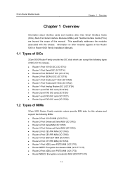
... Interface Cards (SICs), Multi-Functional Interface Modules (MIMs), and Flexible Interface Cards (FICs) are beyond the scope of this manual. z Router 1-Port 10/100 SIC (3C13712) z Router 1-Port Serial SIC (3C13714) z Router 2-Port ISDN-S/T SIC (3C13716) z Router 2-Port ISDN-U SIC (3C13718) z Router 1-Port Fractional T1 SIC (3C13720) z Router 1-Port Fractional E1 SIC (3C13722) z Router 1-Port Analog Modem SIC (3C13724) z Router 1-port FXS SIC card (3C13725) z Router...
... Interface Cards (SICs), Multi-Functional Interface Modules (MIMs), and Flexible Interface Cards (FICs) are beyond the scope of this manual. z Router 1-Port 10/100 SIC (3C13712) z Router 1-Port Serial SIC (3C13714) z Router 2-Port ISDN-S/T SIC (3C13716) z Router 2-Port ISDN-U SIC (3C13718) z Router 1-Port Fractional T1 SIC (3C13720) z Router 1-Port Fractional E1 SIC (3C13722) z Router 1-Port Analog Modem SIC (3C13724) z Router 1-port FXS SIC card (3C13725) z Router...
Installation Guide
Page 10
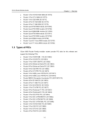
... IMA FIC (3C13875) z Router 1-Port E3 ATM FIC (3C13876) z Router 1-Port T3 ATM FIC (3C13877) z Router 4-Port Fractional T1 FIC (3C13821) z Router 4-Port Fractional E1 FIC (3C13823) z Router 1-Port OC3 POS FIC (3C13881) z Router 1-Port OC-3 ATM MM FIC (3C13882) z Router 1-Port OC-3 ATM SM FIC (3C13884) z Router 1-Port OC-3 ATM SML FIC (3C13886) z Router 1-Port 10/100/1000 FIC (3C13887) z Router 1-Port CE3 FIC (3C13888) z Router 1-Port CT3 FIC (3C13889...
... IMA FIC (3C13875) z Router 1-Port E3 ATM FIC (3C13876) z Router 1-Port T3 ATM FIC (3C13877) z Router 4-Port Fractional T1 FIC (3C13821) z Router 4-Port Fractional E1 FIC (3C13823) z Router 1-Port OC3 POS FIC (3C13881) z Router 1-Port OC-3 ATM MM FIC (3C13882) z Router 1-Port OC-3 ATM SM FIC (3C13884) z Router 1-Port OC-3 ATM SML FIC (3C13886) z Router 1-Port 10/100/1000 FIC (3C13887) z Router 1-Port CE3 FIC (3C13888) z Router 1-Port CT3 FIC (3C13889...
Installation Guide
Page 11
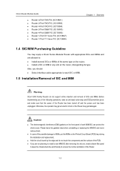
... type on the router, disregarding its type. z If you should: z Select interface cable appropriate to each MIM/SIC can protect the whole router. Otherwise, the operator may get an electric shock or the Router may equip a 3Com Series Modular Router with appropriate SICs ...off and the power cord has been unplugged. 3Com Router Module Guide z Router 4-Port FXS FIC (3C13891) z Router 2-Port FXO FIC (3C13893) z Router 4-Port FXO FIC (3C13894) z Router 2-Port E&M FIC (3C13895) z Router 4-Port E&M FIC (3C13896) z Router 1-Port E1 Voice FIC (3C13897) z Router 1-Port T1 Voice FIC (3C13898) Chapter ...
... type on the router, disregarding its type. z If you should: z Select interface cable appropriate to each MIM/SIC can protect the whole router. Otherwise, the operator may get an electric shock or the Router may equip a 3Com Series Modular Router with appropriate SICs ...off and the power cord has been unplugged. 3Com Router Module Guide z Router 4-Port FXS FIC (3C13891) z Router 2-Port FXO FIC (3C13893) z Router 4-Port FXO FIC (3C13894) z Router 2-Port E&M FIC (3C13895) z Router 4-Port E&M FIC (3C13896) z Router 1-Port E1 Voice FIC (3C13897) z Router 1-Port T1 Voice FIC (3C13898) Chapter ...
Installation Guide
Page 12
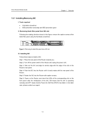
... rotating direction shown in this figure, remove the captive screws of the Router towards you; Step 4: Push the SIC into the Router with the rear panel of the Router; Step 5: Fasten the SIC into the Router until it closely mates with captive screws; Installing SIC Follow these steps ... means that its remote edge with the edge of the Router and unplug the power cord; 3Com Router Module Guide Chapter 1 Overview 1.5.1 Installing/Removing SIC I. Step 6: Power on the Router, and check the LEDs of the corresponding slot on the Router's rear panel; Step 3: Take out the SIC and...
... rotating direction shown in this figure, remove the captive screws of the Router towards you; Step 4: Push the SIC into the Router with the rear panel of the Router; Step 5: Fasten the SIC into the Router until it closely mates with captive screws; Installing SIC Follow these steps ... means that its remote edge with the edge of the Router and unplug the power cord; 3Com Router Module Guide Chapter 1 Overview 1.5.1 Installing/Removing SIC I. Step 6: Power on the Router, and check the LEDs of the corresponding slot on the Router's rear panel; Step 3: Take out the SIC and...
Installation Guide
Page 13
... the captive screws on the front panel: ON means that the POST of the Router and unplug the power cord; Step 3: Unplug all the network interface cables connected to remove a SIC: Step 1: Place the rear panel of the Router; 3Com Router Module Guide Chapter 1 Overview Figure 1-2 Installing SIC IV. Step 5: Pull the SIC outward until...
... the captive screws on the front panel: ON means that the POST of the Router and unplug the power cord; Step 3: Unplug all the network interface cables connected to remove a SIC: Step 1: Place the rear panel of the Router; 3Com Router Module Guide Chapter 1 Overview Figure 1-2 Installing SIC IV. Step 5: Pull the SIC outward until...

Installation Guide
Page 14
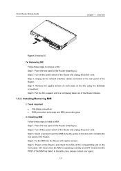
... all interface cables from the bottom of the router. 1.6 Troubleshooting 3Com 5000 Routers LEDs, indicate the state of the module as follows: After the installation of a SIC/MIM, turn on the power and view the corresponding LEDs (such as SLOT0, SLOT1 or SLOT2) on the cover of the Router chassis:...; Step 5: Pull the MIM towards you until it is operating normally and OFF means that the Power-On Self-Test (POST) of the Router towards you; 3Com Router Module Guide Figure 1-3 Installing MIM (1) Chapter 1 Overview Figure 1-4 Installing MIM (2) III. Removing MIM Follow these steps to remove a MIM:...
... all interface cables from the bottom of the router. 1.6 Troubleshooting 3Com 5000 Routers LEDs, indicate the state of the module as follows: After the installation of a SIC/MIM, turn on the power and view the corresponding LEDs (such as SLOT0, SLOT1 or SLOT2) on the cover of the Router chassis:...; Step 5: Pull the MIM towards you until it is operating normally and OFF means that the Power-On Self-Test (POST) of the Router towards you; 3Com Router Module Guide Figure 1-3 Installing MIM (1) Chapter 1 Overview Figure 1-4 Installing MIM (2) III. Removing MIM Follow these steps to remove a MIM:...
Installation Guide
Page 15
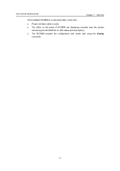
z The SIC/MIM accepts the configuration and works well using the display command. 1-7 3Com Router Module Guide Chapter 1 Overview If the installed SIC/MIM is in abnormal state, check that: z Proper interface cable is used; z The LEDs on the panel of SIC/MIM are displaying normally (see the section introducing the SIC/MIM for its LED status and description);
z The SIC/MIM accepts the configuration and works well using the display command. 1-7 3Com Router Module Guide Chapter 1 Overview If the installed SIC/MIM is in abnormal state, check that: z Proper interface cable is used; z The LEDs on the panel of SIC/MIM are displaying normally (see the section introducing the SIC/MIM for its LED status and description);
Installation Guide
Page 16
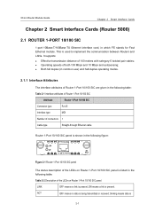
... for Fast Ethernet module. ON means a link is being transmitted or received; 3Com Router Module Guide Chapter 2 Smart Interface Cards Chapter 2 Smart Interface Cards (Router 5000) 2.1 ROUTER 1-PORT 10/100 SIC 1-port 10Base-T/100Base-TX Ethernet interface card, in the following table: Table 2-2 Description of the LEDs on Router 1-Port 10/100 SIC panel LINK OFF means no data is present...
... for Fast Ethernet module. ON means a link is being transmitted or received; 3Com Router Module Guide Chapter 2 Smart Interface Cards Chapter 2 Smart Interface Cards (Router 5000) 2.1 ROUTER 1-PORT 10/100 SIC 1-port 10Base-T/100Base-TX Ethernet interface card, in the following table: Table 2-2 Description of the LEDs on Router 1-Port 10/100 SIC panel LINK OFF means no data is present...
Installation Guide
Page 17
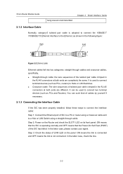
3Com Router Module Guide being received or/and transmitted. You can be used to connect terminal devices (such as PCs, routers) to Hubs or LAN Switches. It can such kind of cables by yourself if necessary. 2.1.3 Connecting the Interface Cable If the SIC has been properly ...connectors at both ends are different. Chapter 2 Smart Interface Cards 2.1.2 Interface Cable Normally, category-5 twisted pair cable is used to the Ethernet, as PCs and Routers). It is adopted to connect the 10BASE-T /100BASE-TX Ethernet interface to connect two terminal devices (such as shown in ...
3Com Router Module Guide being received or/and transmitted. You can be used to connect terminal devices (such as PCs, routers) to Hubs or LAN Switches. It can such kind of cables by yourself if necessary. 2.1.3 Connecting the Interface Cable If the SIC has been properly ...connectors at both ends are different. Chapter 2 Smart Interface Cards 2.1.2 Interface Cable Normally, category-5 twisted pair cable is used to the Ethernet, as PCs and Routers). It is adopted to connect the 10BASE-T /100BASE-TX Ethernet interface to connect two terminal devices (such as shown in ...
Installation Guide
Page 18
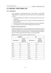
... maximum transmission distance of manual configuration; Table 2-3 Baud rate and transmission distance of synchronous and asynchronous serial data streams; 3Com Router Module Guide 2.2 ROUTER 1-PORT SERIAL SIC Chapter 2 Smart Interface Cards 2.2.1 Introduction 1-port multiprotocol synchronous/asynchronous serial interface card (ROUTER 1-PORT SERIAL SIC) supports both synchronous and asynchronous operating modes. z Local loopback and remote loopback, facilitating fault test...
... maximum transmission distance of manual configuration; Table 2-3 Baud rate and transmission distance of synchronous and asynchronous serial data streams; 3Com Router Module Guide 2.2 ROUTER 1-PORT SERIAL SIC Chapter 2 Smart Interface Cards 2.2.1 Introduction 1-port multiprotocol synchronous/asynchronous serial interface card (ROUTER 1-PORT SERIAL SIC) supports both synchronous and asynchronous operating modes. z Local loopback and remote loopback, facilitating fault test...
Installation Guide
Page 19
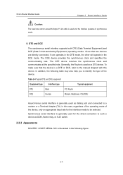
... 2-4 Typical DTE and DCE equipment Equipment type Interface type Typical equipment DTE Male PC, Router DCE Female Modem, Multiplexer, CSU/DSU Asynchronous serial interface is generally used as DDN, frame relay, or X.25 switch. 2.2.2 Appearance ROUTER 1-PORT SERIAL SIC is illustrated in the DCE...mode of the device. DTE and DCE The synchronous serial interface supports both DTE (Data Terminal Equipment) and DCE (Data Circuit-terminating Equipment) operating modes. II. 3Com Router Module Guide Chapter 2 Smart Interface Cards Caution: The baud rate cannot exceed 64 kbps if V.24...
... 2-4 Typical DTE and DCE equipment Equipment type Interface type Typical equipment DTE Male PC, Router DCE Female Modem, Multiplexer, CSU/DSU Asynchronous serial interface is generally used as DDN, frame relay, or X.25 switch. 2.2.2 Appearance ROUTER 1-PORT SERIAL SIC is illustrated in the DCE...mode of the device. DTE and DCE The synchronous serial interface supports both DTE (Data Terminal Equipment) and DCE (Data Circuit-terminating Equipment) operating modes. II. 3Com Router Module Guide Chapter 2 Smart Interface Cards Caution: The baud rate cannot exceed 64 kbps if V.24...

Installation Guide
Page 20
3Com Router Module Guide Chapter 2 Smart Interface Cards Figure 2-3 ROUTER 1-PORT SERIAL SIC 2.2.3 Interface Attributes The interface attributes of ROUTER 1-PORT SERIAL SIC are given in the following table: Table 2-5 Interface attributes of ROUTER 1-PORT SERIAL SIC Attribute Synchronous Description Asynchronous Connector type DB50 Number of 1 connectors Cable type V.24 (RS232) DTE cable V.24 (RS232) DCE cable V.35 DTE ...
3Com Router Module Guide Chapter 2 Smart Interface Cards Figure 2-3 ROUTER 1-PORT SERIAL SIC 2.2.3 Interface Attributes The interface attributes of ROUTER 1-PORT SERIAL SIC are given in the following table: Table 2-5 Interface attributes of ROUTER 1-PORT SERIAL SIC Attribute Synchronous Description Asynchronous Connector type DB50 Number of 1 connectors Cable type V.24 (RS232) DTE cable V.24 (RS232) DCE cable V.35 DTE ...
Installation Guide
Page 21
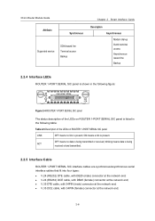
... received; z V.35 DCE cable, with DB25 (female) connector at the network end; 3Com Router Module Guide Attribute Synchronous Supported service DDN leased line Terminal access Backup Chapter 2 Smart Interface Cards Description Asynchronous Modem dial-up Dumb terminal access Asynchronous leased line Backup 2.2.4 Interface LEDs ROUTER 1-PORT SERIAL SIC panel is shown in the following figure: Figure...
... received; z V.35 DCE cable, with DB25 (female) connector at the network end; 3Com Router Module Guide Attribute Synchronous Supported service DDN leased line Terminal access Backup Chapter 2 Smart Interface Cards Description Asynchronous Modem dial-up Dumb terminal access Asynchronous leased line Backup 2.2.4 Interface LEDs ROUTER 1-PORT SERIAL SIC panel is shown in the following figure: Figure...
