
User Guide
Page 19
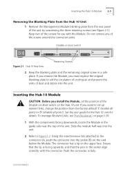
...blanking plate to the connector (A), push the connector into the socket (B) on the Hub 10 unit. Using the insert/remove tab attached to aid the circulation of cooling air and prevent the entry of the Disable-on-Boot switch on the card below the Module. The connector has a lip on page 3-...39. 1 With the components facing downwards, locate the Module in the socket align correctly with the Module. Slide the module half way into the unit. Inserting the Hub 10 Module 2-3 Removing the ...
...blanking plate to the connector (A), push the connector into the socket (B) on the Hub 10 unit. Using the insert/remove tab attached to aid the circulation of cooling air and prevent the entry of the Disable-on-Boot switch on the card below the Module. The connector has a lip on page 3-...39. 1 With the components facing downwards, locate the Module in the socket align correctly with the Module. Slide the module half way into the unit. Inserting the Hub 10 Module 2-3 Removing the ...

User Guide
Page 22
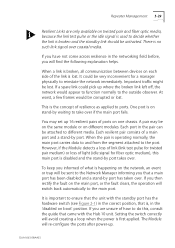
... in the stack, and the unit will flash during the self-test. As a default, the Module powers up the unit with the Module installed, and switch on each unit in the stack will light up , the Module will reset all units in this chapter. Parity, character size and stop bits are...
... in the stack, and the unit will flash during the self-test. As a default, the Module powers up the unit with the Module installed, and switch on each unit in the stack will light up , the Module will reset all units in this chapter. Parity, character size and stop bits are...
User Guide
Page 57
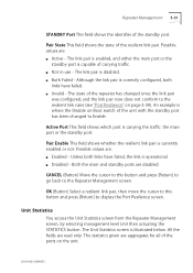
... the port. You may be very inconvenient for fiber optic medium), this , consult the guide that is important to ensure that the unit with the Hub 10 unit. Repeater Management 3-29 Resilient Links are unsure of how to do this main port is disabled and the stand-by port takes over... if the main port fails. Each port in the correct position, that came with the standby port has the hardware switch (see Figure 2-1) in the pair can be lost . Setting the switch correctly will re-configure the ports after power-up 16 resilient pairs of ports on twisted pair and fiber optic...
... the port. You may be very inconvenient for fiber optic medium), this , consult the guide that is important to ensure that the unit with the Hub 10 unit. Repeater Management 3-29 Resilient Links are unsure of how to do this main port is disabled and the stand-by port takes over... if the main port fails. Each port in the correct position, that came with the standby port has the hardware switch (see Figure 2-1) in the pair can be lost . Setting the switch correctly will re-configure the ports after power-up 16 resilient pairs of ports on twisted pair and fiber optic...
User Guide
Page 59
... port. Possible values are disabled. The link pair is enabled, and either the main port or the standby port is where the Disable on Boot switch of the ports on page 3-39). The state of carrying traffic. s Invalid - Both the main and standby ports are : s Enabled - The link pair is illustrated...
... port. Possible values are disabled. The link pair is enabled, and either the main port or the standby port is where the Disable on Boot switch of the ports on page 3-39). The state of carrying traffic. s Invalid - Both the main and standby ports are : s Enabled - The link pair is illustrated...
User Guide
Page 62
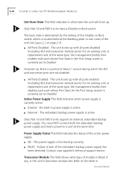
Only Hub 10 and FMS II units have a Disable on Boot switch, which is a period of module is fitted, if any, in power ... All Ports Disabled - The unit boots up with all ports enabled (including AUI and transceiver module ports). Only Hub 10 and FMS II units support an external, redundant backup power supply. Contact your supplier's technical support service. s Internal -...screen) is currently set to Enabled. The boot state is determined by the setting of the Disable on Boot switch. s All Ports Enabled - For an existing unit, or replacement unit of the same type, the management...
Only Hub 10 and FMS II units have a Disable on Boot switch, which is a period of module is fitted, if any, in power ... All Ports Disabled - The unit boots up with all ports enabled (including AUI and transceiver module ports). Only Hub 10 and FMS II units support an external, redundant backup power supply. Contact your supplier's technical support service. s Internal -...screen) is currently set to Enabled. The boot state is determined by the setting of the Disable on Boot switch. s All Ports Enabled - For an existing unit, or replacement unit of the same type, the management...
User Guide
Page 68
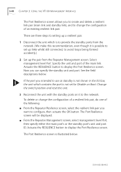
Actuate the RESILIENCE button to display the Port Resilience screen. Change the switch position and reset the unit. 3 Reconnect the unit with the standby ports on it is possible to set for Disable on Boot. Actuate the RESILIENCE ...
Actuate the RESILIENCE button to display the Port Resilience screen. Change the switch position and reset the unit. 3 Reconnect the unit with the standby ports on it is possible to set for Disable on Boot. Actuate the RESILIENCE ...
User Guide
Page 69
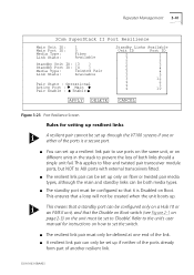
...will not be set the switch. s A resilient link pair can only be set up only on fiber or twisted pair media types, although the main and standby links can be set up if neither of the ports already form part of another resilient link. Repeater Management 3-41 3Com SuperStack II Port Resilience... the same unit, or on how to set to AUI ports with external transceivers fitted. s The resilient link pair must be configured only on a Hub 10 or an FMS II unit, and that it is a secure port. This ensures that a standby port can set up . s The standby port must only be defined...
...will not be set the switch. s A resilient link pair can only be set up only on fiber or twisted pair media types, although the main and standby links can be set up if neither of the ports already form part of another resilient link. Repeater Management 3-41 3Com SuperStack II Port Resilience... the same unit, or on how to set to AUI ports with external transceivers fitted. s The resilient link pair must be configured only on a Hub 10 or an FMS II unit, and that it is a secure port. This ensures that a standby port can set up . s The standby port must only be defined...

User Guide
Page 70
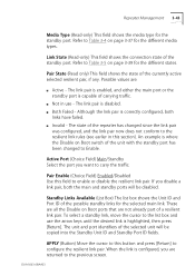
... unit and port from the list box. Refer to the unit's user manual for the main port. You can either enter the identifier of the Hub 10 unit (see Figure 2-1 on page 2-3) with the standby port must not exceed 16. You can achieve this manually by monitoring the fiber receive idle... the identifier of resilient links per stack must be listed as a possible standby link. This means that it will not be set to set the switch. 3-42 CHAPTER 3: USING THE VT100 MANAGEMENT INTERFACE s The number of the main port. Media Type (Read-only) This field shows the media type for instructions...
... unit and port from the list box. Refer to the unit's user manual for the main port. You can either enter the identifier of the Hub 10 unit (see Figure 2-1 on page 2-3) with the standby port must not exceed 16. You can achieve this manually by monitoring the fiber receive idle... the identifier of resilient links per stack must be listed as a possible standby link. This means that it will not be set to set the switch. 3-42 CHAPTER 3: USING THE VT100 MANAGEMENT INTERFACE s The number of the main port. Media Type (Read-only) This field shows the media type for instructions...
User Guide
Page 71
... disable the resilient link pair. Possible values are all the Disable on page 3-37 for the different states. s Both Failed - Refer to Table 3-5 on Boot switch of the repeater has changed to Table 3-4 on Boot ports that are returned to the list box and use - Link State (Read-only) This field...
... disable the resilient link pair. Possible values are all the Disable on page 3-37 for the different states. s Both Failed - Refer to Table 3-5 on Boot switch of the repeater has changed to Table 3-4 on Boot ports that are returned to the list box and use - Link State (Read-only) This field...
User Guide
Page 95
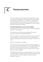
... the device, perform a reset by pressing [Return][Return]. For serial port access, check you have performed the wake-up procedure correctly, by pressing the Reset switch at the rear of times, contact your terminal or emulator. Check the settings on the front of a problem, should be green. It lists symptoms that...
... the device, perform a reset by pressing [Return][Return]. For serial port access, check you have performed the wake-up procedure correctly, by pressing the Reset switch at the rear of times, contact your terminal or emulator. Check the settings on the front of a problem, should be green. It lists symptoms that...
User Guide
Page 97
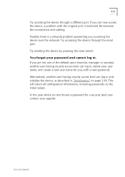
Try resetting the device by pressing the reset switch. In the case where no-one of the default users (monitor, manager or security), another user having security access level can log in, delete your ...
Try resetting the device by pressing the reset switch. In the case where no-one of the default users (monitor, manager or security), another user having security access level can log in, delete your ...
User Guide
Page 105
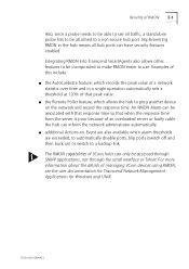
... ping another device on ) or switch to automatically disable ports, blip ports (switch off and then back on the network and record the response time. Implementing RMON in a single operation automatically sets a threshold at 120% of managing 3Com devices using RMON, see all hub ports can only be attached to use. s the Remote Poller...
... ping another device on ) or switch to automatically disable ports, blip ports (switch off and then back on the network and record the response time. Implementing RMON in a single operation automatically sets a threshold at 120% of managing 3Com devices using RMON, see all hub ports can only be attached to use. s the Remote Poller...

User Guide
Page 112
Send Trap. Notify and blip port. Turn port on . Disable port. Turn port on after 5 seconds. Notify and switch resilient port. If port is the Main of a resilient pair then switch to original state after 5 seconds. Turn all ports on . Turn ports back to standby. Notify and enable port. Send Trap. Turn port...
Send Trap. Notify and blip port. Turn port on . Disable port. Turn port on after 5 seconds. Notify and switch resilient port. If port is the Main of a resilient pair then switch to original state after 5 seconds. Turn all ports on . Turn ports back to standby. Notify and enable port. Send Trap. Turn port...


