User Guide
Page 13
... Manager for example, you can configure traps to be restricted to the management facilities. s Set up resilient links. s Implement security features. Using SNMP management, for Windows (3C15000 series). Each network manager provides its own user interface to a particular port. 1 INTRODUCTION Overview The Management Module and Advanced RMON Module are exceeded. s Poll other devices on the network. SmartAgent software in the stack. When installed, the Modules allow you to : s Monitor and change the configuration of units. You can view...
... Manager for example, you can configure traps to be restricted to the management facilities. s Set up resilient links. s Implement security features. Using SNMP management, for Windows (3C15000 series). Each network manager provides its own user interface to a particular port. 1 INTRODUCTION Overview The Management Module and Advanced RMON Module are exceeded. s Poll other devices on the network. SmartAgent software in the stack. When installed, the Modules allow you to : s Monitor and change the configuration of units. You can view...
User Guide
Page 22
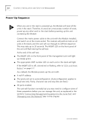
... number of the management unit will light. Parity, character size and stop bits are fixed.) s All ports enabled. 2-6 CHAPTER 2: INSTALLATION AND SETUP FOR MANAGEMENT Power Up Sequence When any other units in the stack before you may take up steady green. The MGMT LED on each unit in the stack will light up to "LEDs and Reset Button" on all the units in the stack. DUA1663-0BAA03 As a default, the Module powers...
... number of the management unit will light. Parity, character size and stop bits are fixed.) s All ports enabled. 2-6 CHAPTER 2: INSTALLATION AND SETUP FOR MANAGEMENT Power Up Sequence When any other units in the stack before you may take up steady green. The MGMT LED on each unit in the stack will light up to "LEDs and Reset Button" on all the units in the stack. DUA1663-0BAA03 As a default, the Module powers...
User Guide
Page 24
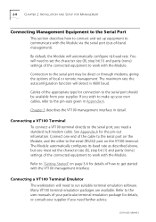
... size (8), stop bit (1) and parity (none) settings of the connected equipment to get started with the Module. Refer to the user manuals of local or remote management. Connecting a VT100 Terminal To connect a VT100 terminal directly to run suitable terminal emulation software. See Appendix A for connection to the pin-outs given in detail. Many VT100 terminal emulation packages are available. Connection to work with the VT100 management interface. The Module automatically configures its baud rate...
... size (8), stop bit (1) and parity (none) settings of the connected equipment to get started with the Module. Refer to the user manuals of local or remote management. Connecting a VT100 Terminal To connect a VT100 terminal directly to run suitable terminal emulation software. See Appendix A for connection to the pin-outs given in detail. Many VT100 terminal emulation packages are available. Connection to work with the VT100 management interface. The Module automatically configures its baud rate...
User Guide
Page 25
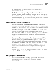
... and model. You can communicate with the VT100 management interface. Refer to "Getting Started" on page A-5 if you are using Telnet or SNMP out-of-band management. This involves setting up the SLIP parameters using the VT100 management interface. Connecting a Workstation Running SLIP You can set the parameters using either a network connection or a serial port connection. The cables you require to get started with the Module. The section "Setup" on its baud rate to...
... and model. You can communicate with the VT100 management interface. Refer to "Getting Started" on page A-5 if you are using Telnet or SNMP out-of-band management. This involves setting up the SLIP parameters using the VT100 management interface. Connecting a Workstation Running SLIP You can set the parameters using either a network connection or a serial port connection. The cables you require to get started with the Module. The section "Setup" on its baud rate to...
User Guide
Page 26
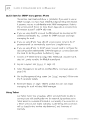
... 2: INSTALLATION AND SETUP FOR MANAGEMENT Quick Start for more information about IP and IPX addresses. s If you are using the IPX protocol, the Module will be automatically loaded and brought into use an SNMP manager, once you wish to configure the stack's IP parameters before the SNMP manager can now begin managing the stack. Using Telnet Any Telnet facility that emulates a VT100 terminal should be allocated an IPX address automatically. If a connection...
... 2: INSTALLATION AND SETUP FOR MANAGEMENT Quick Start for more information about IP and IPX addresses. s If you are using the IPX protocol, the Module will be automatically loaded and brought into use an SNMP manager, once you wish to configure the stack's IP parameters before the SNMP manager can now begin managing the stack. Using Telnet Any Telnet facility that emulates a VT100 terminal should be allocated an IPX address automatically. If a connection...
User Guide
Page 27
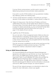
... in this . The use of 3Com network managers is emulating a VT100 terminal. The VT100 management interface is installed correctly at the management station. Any SNMP based network manager can manage SuperStack II Huub 10 and LinkBuilder FMS Series units, provided the MIB (Management Information Base) is described in detail in Chapter 3. For more information, contact your SuperStack II Hub 10 units. Managing over the Network 2-11 To set up Telnet communications, you are unsure...
... in this . The use of 3Com network managers is emulating a VT100 terminal. The VT100 management interface is installed correctly at the management station. Any SNMP based network manager can manage SuperStack II Huub 10 and LinkBuilder FMS Series units, provided the MIB (Management Information Base) is described in detail in Chapter 3. For more information, contact your SuperStack II Hub 10 units. Managing over the Network 2-11 To set up Telnet communications, you are unsure...
User Guide
Page 28
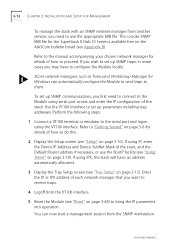
... the Ask3Com bulletin board (see "Trap Setup" on page 3-48) to bring the IP parameters into operation. Refer to "Getting Started" on page 3-6 for the SuperStack II Hub 10 Series is available free on page 3-10). 2-12 CHAPTER 2: INSTALLATION AND SETUP FOR MANAGEMENT To manage the stack with an SNMP network manager from another vendor, you need to connect to the Module using serial port access and enter the IP...
... the Ask3Com bulletin board (see "Trap Setup" on page 3-48) to bring the IP parameters into operation. Refer to "Getting Started" on page 3-6 for the SuperStack II Hub 10 Series is available free on page 3-10). 2-12 CHAPTER 2: INSTALLATION AND SETUP FOR MANAGEMENT To manage the stack with an SNMP network manager from another vendor, you need to connect to the Module using serial port access and enter the IP...
User Guide
Page 36
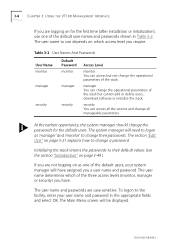
... time (after installation or initialization), use depends on which of the default user names and passwords shown in the appropriate fields and select OK. Initializing the stack returns the passwords to change the operational parameters of the stack but cannot add or delete users, download software or initialize the stack. The user name determines which access level you have assigned you a user name and password. DUA1663-0BAA03 Table 3-2 User Names And Passwords User Name monitor manager...
... time (after installation or initialization), use depends on which of the default user names and passwords shown in the appropriate fields and select OK. Initializing the stack returns the passwords to change the operational parameters of the stack but cannot add or delete users, download software or initialize the stack. The user name determines which access level you have assigned you a user name and password. DUA1663-0BAA03 Table 3-2 User Names And Passwords User Name monitor manager...
User Guide
Page 39
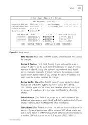
...: [FFFF0000 ] SLIP SubNet Mask:[255.255.255.0 ] Default Router: [0.0.0.0 ] BootP Select: x Enabled x IPX Network Node [00000000]: 08004E098765 [00000000]: 08004E098765 [00000000]: 08004E098765 [00000000]: 08004E098765 Status x Enabled x x Enabled x x Enabled x x Enabled x Data Link Protocol Ethernet_802.3 Ethernet_802.2 Ethernet_II Ethernet_SNAP OK SETUP TRAPS SERIAL PORT CANCEL Figure 3-6 Setup Screen MAC Address (Read-only) The MAC address of the default router on page A-5.) You may use out-of-band Telnet or SNMP management, either locally or remotely via a modem. This cannot be...
...: [FFFF0000 ] SLIP SubNet Mask:[255.255.255.0 ] Default Router: [0.0.0.0 ] BootP Select: x Enabled x IPX Network Node [00000000]: 08004E098765 [00000000]: 08004E098765 [00000000]: 08004E098765 [00000000]: 08004E098765 Status x Enabled x x Enabled x x Enabled x x Enabled x Data Link Protocol Ethernet_802.3 Ethernet_802.2 Ethernet_II Ethernet_SNAP OK SETUP TRAPS SERIAL PORT CANCEL Figure 3-6 Setup Screen MAC Address (Read-only) The MAC address of the default router on page A-5.) You may use out-of-band Telnet or SNMP management, either locally or remotely via a modem. This cannot be...
User Guide
Page 40
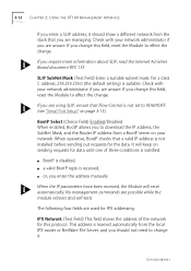
... default setting) is learned automatically from the stack that you should show a different network from the local IPX router or NetWare File Server, and you are unsure. When operative, BootP checks that Flow Control is not installed before sending out requests for IPX addressing. No management commands are used for the data. BootP Select (Choice Field) Enabled/Disabled When enabled, BootP allows you to XON/XOFF (see "Serial Port Setup" on your network...
... default setting) is learned automatically from the stack that you should show a different network from the local IPX router or NetWare File Server, and you are unsure. When operative, BootP checks that Flow Control is not installed before sending out requests for IPX addressing. No management commands are used for the data. BootP Select (Choice Field) Enabled/Disabled When enabled, BootP allows you to XON/XOFF (see "Serial Port Setup" on your network...
User Guide
Page 47
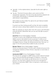
... the management facilities via SNMP using a remote network manager such as Manager. Make any changes you change the default password (see "Edit User" on your network. Community SNMP (Choice Field) Enabled / Disabled The stack can use [Ctrl]+[B] to jump to all access to the system administrator or somebody with the system administrator's responsibilities. This level of problems on page 3-21) for each access level. The options for the permanently-enabled security access level...
... the management facilities via SNMP using a remote network manager such as Manager. Make any changes you change the default password (see "Edit User" on your network. Community SNMP (Choice Field) Enabled / Disabled The stack can use [Ctrl]+[B] to jump to all access to the system administrator or somebody with the system administrator's responsibilities. This level of problems on page 3-21) for each access level. The options for the permanently-enabled security access level...
User Guide
Page 48
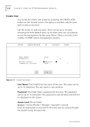
... 3: USING THE VT100 MANAGEMENT INTERFACE Create User You access the Create User screen by cycling through the options using Telnet. The name can concurrently access the management facility using the space bar. This option is case sensitive and will not be up to 10 characters. There is case sensitive. Up to three users can be up to the number of SNMP remote management sessions. 3Com SuperStack II Create User User Name: Password: [bob [ ] ] Access Level: x Monitor...
... 3: USING THE VT100 MANAGEMENT INTERFACE Create User You access the Create User screen by cycling through the options using Telnet. The name can concurrently access the management facility using the space bar. This option is case sensitive and will not be up to 10 characters. There is case sensitive. Up to three users can be up to the number of SNMP remote management sessions. 3Com SuperStack II Create User User Name: Password: [bob [ ] ] Access Level: x Monitor...
User Guide
Page 66
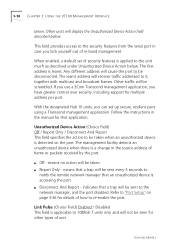
... disconnected. Refer to 10BASE-T units only and will display the Unauthorized Device Action field described below . DUA1663-0BAA03 If you use a 3Com Transcend management application, you have greater control over security, including support for other types of frame or packets received by the port. Link Pulse (Choice Field) Enabled / Disabled This field is accessing the port. This field provides access to be seen for multiple address per port. Unauthorized...
... disconnected. Refer to 10BASE-T units only and will display the Unauthorized Device Action field described below . DUA1663-0BAA03 If you use a 3Com Transcend management application, you have greater control over security, including support for other types of frame or packets received by the port. Link Pulse (Choice Field) Enabled / Disabled This field is accessing the port. This field provides access to be seen for multiple address per port. Unauthorized...
User Guide
Page 68
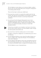
... screen is possible to set for Disable on Boot. To delete or change the configuration of a resilient link pair, do one of the following: s From the Repeater Resilience screen, select the resilient link pair you to create and delete a resilient link pair (main link and standby link), and to change the configuration of the main link. 3-40 CHAPTER 3: USING THE VT100 MANAGEMENT INTERFACE The Port Resilience screen allows you want...
... screen is possible to set for Disable on Boot. To delete or change the configuration of a resilient link pair, do one of the following: s From the Repeater Resilience screen, select the resilient link pair you to create and delete a resilient link pair (main link and standby link), and to change the configuration of the main link. 3-40 CHAPTER 3: USING THE VT100 MANAGEMENT INTERFACE The Port Resilience screen allows you want...
User Guide
Page 70
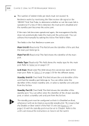
... main port is disabled and the standby port becomes the active port. DUA1663-0BAA03 If a loss of the standby port. You can either enter the identifier of the chosen standby port, or select a standby unit and port from the list box. 3-42 CHAPTER 3: USING THE VT100 MANAGEMENT INTERFACE s The number of resilient links per stack must be configured so that the standby port belongs to. Refer to Table...
... main port is disabled and the standby port becomes the active port. DUA1663-0BAA03 If a loss of the standby port. You can either enter the identifier of the chosen standby port, or select a standby unit and port from the list box. 3-42 CHAPTER 3: USING THE VT100 MANAGEMENT INTERFACE s The number of resilient links per stack must be configured so that the standby port belongs to. Refer to Table...
User Guide
Page 77
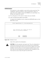
... make unused disabled ports enabled and thus available to the factory defaults. You should only initialize the stack if: s The configuration of the stack no longer suits your network. All ports will change the device back to users. The initialization operation performs a reset as described in addition returns the NVRAM to users with great care. CAUTION: Use this operation with security access level. s Other troubleshooting efforts have failed.
... make unused disabled ports enabled and thus available to the factory defaults. You should only initialize the stack if: s The configuration of the stack no longer suits your network. All ports will change the device back to users. The initialization operation performs a reset as described in addition returns the NVRAM to users with great care. CAUTION: Use this operation with security access level. s Other troubleshooting efforts have failed.

User Guide
Page 89
... SUPPORT 3Com provides easy access to technical support information through the following on-line systems: s 3Com Bulletin Board Service (3ComBBS) s World Wide Web site s ThreeComForum on CompuServe® s 3ComFactsSM automated fax service 3Com Bulletin Board Service 3ComBBS contains patches, software, and drivers for all 3Com products, as well as technical articles. Access by Modem To reach the service by modem, set your modem to 14400 bps Telephone Number...
... SUPPORT 3Com provides easy access to technical support information through the following on-line systems: s 3Com Bulletin Board Service (3ComBBS) s World Wide Web site s ThreeComForum on CompuServe® s 3ComFactsSM automated fax service 3Com Bulletin Board Service 3ComBBS contains patches, software, and drivers for all 3Com products, as well as technical articles. Access by Modem To reach the service by modem, set your modem to 14400 bps Telephone Number...
User Guide
Page 95
... problems can occur when using the management facility. It will not display. The initial Main Banner screen will help you perform a reset a number of the Module once. Now check the MGMT LED on your terminal or terminal emulator is disabled. This appendix collects together this troubleshooting information. The LED should one arise, and to operate as described in Chapter 2. If it is no Module installed...
... problems can occur when using the management facility. It will not display. The initial Main Banner screen will help you perform a reset a number of the Module once. Now check the MGMT LED on your terminal or terminal emulator is disabled. This appendix collects together this troubleshooting information. The LED should one arise, and to operate as described in Chapter 2. If it is no Module installed...
User Guide
Page 113
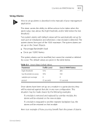
... on that slot in the table below the low threshold. If a module is removed and replaced by the following examples. The system alarms form part of your management application. The system alarms are given in any new configuration. The default values are set up on the Smart Objects: s Percentage Bandwidth Used s Errors per average 4 period 15 seconds Errors/10000 frames 200 100 4 15 seconds Once...
... on that slot in the table below the low threshold. If a module is removed and replaced by the following examples. The system alarms form part of your management application. The system alarms are given in any new configuration. The default values are set up on the Smart Objects: s Percentage Bandwidth Used s Errors per average 4 period 15 seconds Errors/10000 frames 200 100 4 15 seconds Once...
User Guide
Page 125
... 1-1 hardware version 3-46 LEDs 2-7 powering up 2-6 reset button 2-7 upgrading software 3-50 map of screens 3-5 media type 3-35, 3-37, 3-42, 3-43 MGMT LED 2-7 modem cable pin-outs A-4 multicast frames D-3 N NetWare file server A-5 network manager community string 3-14 managing stack using 2-11 network supplier support B-3 node (IPX) 3-12 null modem cable pin-outs A-3 O OK button 3-3 on-line technical services B-1 out-of-band management 2-8 P pair enable 3-31 pair state 3-30 parity (serial port setup) 3-16 partition state 3-39 passwords changing 3-21 creating 3-20 default 3-8 PC-AT serial cable...
... 1-1 hardware version 3-46 LEDs 2-7 powering up 2-6 reset button 2-7 upgrading software 3-50 map of screens 3-5 media type 3-35, 3-37, 3-42, 3-43 MGMT LED 2-7 modem cable pin-outs A-4 multicast frames D-3 N NetWare file server A-5 network manager community string 3-14 managing stack using 2-11 network supplier support B-3 node (IPX) 3-12 null modem cable pin-outs A-3 O OK button 3-3 on-line technical services B-1 out-of-band management 2-8 P pair enable 3-31 pair state 3-30 parity (serial port setup) 3-16 partition state 3-39 passwords changing 3-21 creating 3-20 default 3-8 PC-AT serial cable...


