
Getting Started Guide
Page 5
...UP Power Up 29 Power-up Diagnostics 30 System Diagnostics 30 Power LED Activity 30 Fault LED Activity 30 Gigabit Ethernet Port Diagnostics 30 Packet LED Activity 30 Status LED Activity 30 System Checks 31 Next Step: Software Configuration 31 Back Panel 14... Top 17 Installing the System in This Guide 7 Conventions 8 CoreBuilder 9400 Documentation 9 Paper Documents 9 Software and Documents on CD-ROM 10 Documentation Comments 10 Year 2000 Compliance 10 1 SYSTEM AND SETUP OVERVIEW CoreBuilder 9400 Intelligent Switch 11 System Features and Benefits 11 System Management 12 Network Configuration...
...UP Power Up 29 Power-up Diagnostics 30 System Diagnostics 30 Power LED Activity 30 Fault LED Activity 30 Gigabit Ethernet Port Diagnostics 30 Packet LED Activity 30 Status LED Activity 30 System Checks 31 Next Step: Software Configuration 31 Back Panel 14... Top 17 Installing the System in This Guide 7 Conventions 8 CoreBuilder 9400 Documentation 9 Paper Documents 9 Software and Documents on CD-ROM 10 Documentation Comments 10 Year 2000 Compliance 10 1 SYSTEM AND SETUP OVERVIEW CoreBuilder 9400 Intelligent Switch 11 System Features and Benefits 11 System Management 12 Network Configuration...
Getting Started Guide
Page 6
5 QUICK SETUP FOR MANAGEMENT ACCESS About CoreBuilder 9400 System Management 33 Terminal Connection 34 Modem Connection 34 IP Management Interface 34 Initial Management Access 35 Changing the Console Port Baud Setting 35 Configuring the IP Interface 36 In-band Management 36 Out-of-band Management 36 6 TROUBLESHOOTING THE ... 48 Protective Grounding for the Rack 48 Space Requirements for the Rack 48 Mechanical Requirements for Repair 57 INDEX 3COM CORPORATION LIMITED WARRANTY Building Codes 50 U.S. Electrical Codes 51 D TECHNICAL SUPPORT Online Technical Services 53 World Wide Web Site 53...
5 QUICK SETUP FOR MANAGEMENT ACCESS About CoreBuilder 9400 System Management 33 Terminal Connection 34 Modem Connection 34 IP Management Interface 34 Initial Management Access 35 Changing the Console Port Baud Setting 35 Configuring the IP Interface 36 In-band Management 36 Out-of-band Management 36 6 TROUBLESHOOTING THE ... 48 Protective Grounding for the Rack 48 Space Requirements for the Rack 48 Mechanical Requirements for Repair 57 INDEX 3COM CORPORATION LIMITED WARRANTY Building Codes 50 U.S. Electrical Codes 51 D TECHNICAL SUPPORT Online Technical Services 53 World Wide Web Site 53...

Getting Started Guide
Page 7
on page 33 Setting the Console port baud "Changing the Console Port Baud Setting" on page 35 Configuring the IP management "IP Management Interface" on interface page 34 Troubleshooting hardware and software problems "...and Release Notes that you are shipped with your network. When you have a working knowledge of your CoreBuilder 9400 system, see the Command Reference Guide and the Corebuilder 9400 Implementation Guide on page 18 Cabling the CoreBuilder 9400 system Chapter 3 Checking system power-up , configuring, and troubleshooting. If the information in the Release...
on page 33 Setting the Console port baud "Changing the Console Port Baud Setting" on page 35 Configuring the IP management "IP Management Interface" on interface page 34 Troubleshooting hardware and software problems "...and Release Notes that you are shipped with your network. When you have a working knowledge of your CoreBuilder 9400 system, see the Command Reference Guide and the Corebuilder 9400 Implementation Guide on page 18 Cabling the CoreBuilder 9400 system Chapter 3 Checking system power-up , configuring, and troubleshooting. If the information in the Release...
Getting Started Guide
Page 11
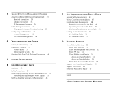
... major features and components of the system s A network configuration example CoreBuilder 9400 Intelligent Switch The CoreBuilder 9400 system delivers full line rate switching among switches, the system supports trunking, which allows you to configure up to six Gigabit Ethernet ports into a single multigigabit connection for a maximum of 3Com's CoreBuilder family. To deliver even higher performance rates among all Gigabit Ethernet...
... major features and components of the system s A network configuration example CoreBuilder 9400 Intelligent Switch The CoreBuilder 9400 system delivers full line rate switching among switches, the system supports trunking, which allows you to configure up to six Gigabit Ethernet ports into a single multigigabit connection for a maximum of 3Com's CoreBuilder family. To deliver even higher performance rates among all Gigabit Ethernet...
Getting Started Guide
Page 12
...can, in turn, pass its traffic along to place the CoreBuilder 9400 in three ways: s CoreBuilder 9400 Administration Console s Standard network management applications based on SNMP, such as a roving analysis port through a SuperStack II Switch 3900. This architecture eliminates bottlenecks caused by providing a secondary... These servers must support a large number of desktop clients into Gigabit Ethernet streams for VLANs and RMON-1, as well as 3Com's Transcend applications, Sun's SunNet Manager, HP's OpenView, and IBM's NetView AIX applications s Web Management suite of your ...
...can, in turn, pass its traffic along to place the CoreBuilder 9400 in three ways: s CoreBuilder 9400 Administration Console s Standard network management applications based on SNMP, such as a roving analysis port through a SuperStack II Switch 3900. This architecture eliminates bottlenecks caused by providing a secondary... These servers must support a large number of desktop clients into Gigabit Ethernet streams for VLANs and RMON-1, as well as 3Com's Transcend applications, Sun's SunNet Manager, HP's OpenView, and IBM's NetView AIX applications s Web Management suite of your ...

Getting Started Guide
Page 13
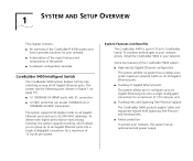
Front Panel Figure 1 Front Panel of the CoreBuilder 9400 System 10BASE-TX Out-of-band Management Port Console Port Allows you to connect a workstation/terminal/modem to the CoreBuilder® 9400 system for management access LEDs Provide information about the system and each port ® R 3C94024 TX 1 RX 1000BASE SX TX 2 RX 1000BASE SX TX 3 RX PCKT STAT ... green = enabled, link OK flashing green = disabled, link OK off = link fail PCKT STAT 17 18 PCKT STAT 23 24 Fan tray 1000BASE-SX Ports 1000BASE GBIC Ports System Overview - Front Panel 13 System Overview -
Front Panel Figure 1 Front Panel of the CoreBuilder 9400 System 10BASE-TX Out-of-band Management Port Console Port Allows you to connect a workstation/terminal/modem to the CoreBuilder® 9400 system for management access LEDs Provide information about the system and each port ® R 3C94024 TX 1 RX 1000BASE SX TX 2 RX 1000BASE SX TX 3 RX PCKT STAT ... green = enabled, link OK flashing green = disabled, link OK off = link fail PCKT STAT 17 18 PCKT STAT 23 24 Fan tray 1000BASE-SX Ports 1000BASE GBIC Ports System Overview - Front Panel 13 System Overview -
Getting Started Guide
Page 19
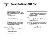
Overview of Cabling The CoreBuilder 9400 system is a Gigabit Ethernet switch with this fixed configuration: s Twelve 1000BASE-SX ports s Twelve 1000BASE GBIC ports (LX or SX transceivers) Fiber Safety Precautions The CoreBuilder 9400 system uses lasers in this point. If you are staging the system, you do not look ... The fiber optic lasers used in its fiber optic ports. It gives an overview of cabling and describes how to cable: s Gigabit Ethernet ports s Console port s Out-of-band management port When all of bright light, however, 3Com recommends that you cable it to the network at...
Overview of Cabling The CoreBuilder 9400 system is a Gigabit Ethernet switch with this fixed configuration: s Twelve 1000BASE-SX ports s Twelve 1000BASE GBIC ports (LX or SX transceivers) Fiber Safety Precautions The CoreBuilder 9400 system uses lasers in this point. If you are staging the system, you do not look ... The fiber optic lasers used in its fiber optic ports. It gives an overview of cabling and describes how to cable: s Gigabit Ethernet ports s Console port s Out-of-band management port When all of bright light, however, 3Com recommends that you cable it to the network at...

Getting Started Guide
Page 20
... a modal bandwidth specification of 400 MHz*km for distances of up to 275 m (902 ft). 20 CHAPTER 3: CABLING COREBUILDER 9400 PORTS Cabling Gigabit Ethernet Ports Before you need to configure trunks, resilient links, or the Spanning Tree Protocol (STP). To avoid bridge loops, configure trunks...up to 500 m (1645 ft). The specification requires and specifies 5 km (3.1 mi). Guidelines for details. See "Cleaning Dirty Fiber Optic Ports and Connectors" on the system (chapter 4) if you cable the system, consider this cable ensures reliability over the maximum 550 m distance. ...
... a modal bandwidth specification of 400 MHz*km for distances of up to 275 m (902 ft). 20 CHAPTER 3: CABLING COREBUILDER 9400 PORTS Cabling Gigabit Ethernet Ports Before you need to configure trunks, resilient links, or the Spanning Tree Protocol (STP). To avoid bridge loops, configure trunks...up to 500 m (1645 ft). The specification requires and specifies 5 km (3.1 mi). Guidelines for details. See "Cleaning Dirty Fiber Optic Ports and Connectors" on the system (chapter 4) if you cable the system, consider this cable ensures reliability over the maximum 550 m distance. ...

Getting Started Guide
Page 21
... on the right. Figure 5 Cabling the 1000BASE-SX Port R 3C94024 1000BASE SX R PCKT TX 1 RX TX 2 RX TX 3 RX STAT 1000BASE SX TX 4 RX TX 7 RX... TX 11 RX TX 12 RX 19 SC connector Fiber cables Cabling 1000BASE-SX Ports To cable one male connector of the SC cable connector pair to the right side of a fixed Gigabit Ethernet... notice that nothing blocks the light transmission between the port and its connectors. 4 Attach one of the 1000BASE-SX ports with SC connectors: 1 Read the Caution at the beginning of "Cabling Gigabit Ethernet Ports" earlier in this chapter. 2 Remove the dust ...
... on the right. Figure 5 Cabling the 1000BASE-SX Port R 3C94024 1000BASE SX R PCKT TX 1 RX TX 2 RX TX 3 RX STAT 1000BASE SX TX 4 RX TX 7 RX... TX 11 RX TX 12 RX 19 SC connector Fiber cables Cabling 1000BASE-SX Ports To cable one male connector of the SC cable connector pair to the right side of a fixed Gigabit Ethernet... notice that nothing blocks the light transmission between the port and its connectors. 4 Attach one of the 1000BASE-SX ports with SC connectors: 1 Read the Caution at the beginning of "Cabling Gigabit Ethernet Ports" earlier in this chapter. 2 Remove the dust ...
Getting Started Guide
Page 22
... multimode fiber with duplex SC connector 22 CHAPTER 3: CABLING COREBUILDER 9400 PORTS Cabling 1000BASE GBIC Ports Each 1000BASE GBIC (Gigabit Interface Converter) port accepts one of "Cabling Gigabit Ethernet Ports" earlier in this chapter. 2 Orient the transceiver so that 3Com supports. Use this transceiver to connect the GBIC port directly to single-mode fiber-optic cable or to...
... multimode fiber with duplex SC connector 22 CHAPTER 3: CABLING COREBUILDER 9400 PORTS Cabling 1000BASE GBIC Ports Each 1000BASE GBIC (Gigabit Interface Converter) port accepts one of "Cabling Gigabit Ethernet Ports" earlier in this chapter. 2 Orient the transceiver so that 3Com supports. Use this transceiver to connect the GBIC port directly to single-mode fiber-optic cable or to...
Getting Started Guide
Page 23
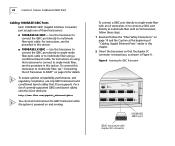
... the LX Transceiver to the upward position. Compress the side tabs and gently pull the transceiver out of the port. Figure 7 Removing the SC Connector Cover SC connector cover Cabling Gigabit Ethernet Ports 23 5 Plug the male duplex SC connector on the fiber optic network cable into place. 4 If you ...place (or until it any further). OR s Front lever - OR s Front lever - Move the front lever to lock the transceiver into the duplex SC port on page 24 for details. Move the front lever to MMF" on the GBIC transceiver, as shown in Figure 8. 3 Do one of the following, depending...
... the LX Transceiver to the upward position. Compress the side tabs and gently pull the transceiver out of the port. Figure 7 Removing the SC Connector Cover SC connector cover Cabling Gigabit Ethernet Ports 23 5 Plug the male duplex SC connector on the fiber optic network cable into place. 4 If you ...place (or until it any further). OR s Front lever - OR s Front lever - Move the front lever to lock the transceiver into the duplex SC port on page 24 for details. Move the front lever to MMF" on the GBIC transceiver, as shown in Figure 8. 3 Do one of the following, depending...
Getting Started Guide
Page 24
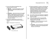
... cable to multimode fiber using an LX transceiver: 1 Read and follow the "Fiber Safety Precautions" on the transmit side of the cable that 3Com supports. 24 CHAPTER 3: CABLING COREBUILDER 9400 PORTS Figure 8 Cabling the GBIC Transceiver 0BASE TX TUS PACKET CONSOLE FAULT POWER 1000BASE (GBIC) 14 15 16 1000BASE (GBIC) 20 21 22 STATUS...
... cable to multimode fiber using an LX transceiver: 1 Read and follow the "Fiber Safety Precautions" on the transmit side of the cable that 3Com supports. 24 CHAPTER 3: CABLING COREBUILDER 9400 PORTS Figure 8 Cabling the GBIC Transceiver 0BASE TX TUS PACKET CONSOLE FAULT POWER 1000BASE (GBIC) 14 15 16 1000BASE (GBIC) 20 21 22 STATUS...
Getting Started Guide
Page 25
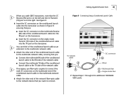
...transceivers, note that you : s Insert the SC connector on the multimode Receive (RX) side of the conditioned launch cable into the TX port on the transceiver. You can think of the conditioned launch cable as shown in Figure 9, ensuring that you : s Connect the multimode ...A RX TX SC connector B A Offset A A = Multimode fiber B = Single-mode fiber 7 Repeat steps 1 through 6 for additional 1000BASE GBIC ports. Cabling Gigabit Ethernet Ports 25 When you want to connect. See Figure 9. 4 Insert the SC connectors on the conditioned launch cable into the transceiver as an extension to...
...transceivers, note that you : s Insert the SC connector on the multimode Receive (RX) side of the conditioned launch cable into the TX port on the transceiver. You can think of the conditioned launch cable as shown in Figure 9, ensuring that you : s Connect the multimode ...A RX TX SC connector B A Offset A A = Multimode fiber B = Single-mode fiber 7 Repeat steps 1 through 6 for additional 1000BASE GBIC ports. Cabling Gigabit Ethernet Ports 25 When you want to connect. See Figure 9. 4 Insert the SC connectors on the conditioned launch cable into the transceiver as an extension to...

Getting Started Guide
Page 26
... the system for management access through any Gigabit Ethernet port using Telnet. The Console port has a male 9-pin, D-type connector. See Figure 10. 2 Attach the other end of the CoreBuilder 9400, the Console port provides an RS-232 connection to establish a connection between... your terminal or workstation. 26 CHAPTER 3: CABLING COREBUILDER 9400 PORTS Cabling the Console Port The Console port provides access for pin-out information. To cable the Console port: 1 Attach the female DB-9 cable connector to connect an external modem, ...
... the system for management access through any Gigabit Ethernet port using Telnet. The Console port has a male 9-pin, D-type connector. See Figure 10. 2 Attach the other end of the CoreBuilder 9400, the Console port provides an RS-232 connection to establish a connection between... your terminal or workstation. 26 CHAPTER 3: CABLING COREBUILDER 9400 PORTS Cabling the Console Port The Console port provides access for pin-out information. To cable the Console port: 1 Attach the female DB-9 cable connector to connect an external modem, ...

Getting Started Guide
Page 27
... out-of -band network management, see the Command Reference Guide. To configure your CoreBuilder 9400 to use the 10BASE-TX port on the 10BASE-TX cable into the 10BASE-TX port until it carries no network traffic. This port is not a switch port, that is a port for management purposes only. It is , it clicks into place. Not used...
... out-of -band network management, see the Command Reference Guide. To configure your CoreBuilder 9400 to use the 10BASE-TX port on the 10BASE-TX cable into the 10BASE-TX port until it carries no network traffic. This port is not a switch port, that is a port for management purposes only. It is , it clicks into place. Not used...

Getting Started Guide
Page 28
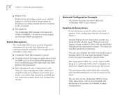
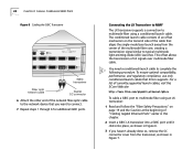
28 CHAPTER 3: CABLING COREBUILDER 9400 PORTS Figure 11 Cabling the Out-of-Band Management Port Out-of-band management port 10BASE TX STATUS PACKET T CONSOLE FAULT POWER 1000BASE (GBIC) 14 15 16 1000BASE (GBIC) 20 21 22 STATUS green = enabled, link OK flashing green = disabled, link OK off = link fail PCKT STAT 17 18 PCKT STAT 23 24 Male RJ-45 connector 10BASE-T cable
28 CHAPTER 3: CABLING COREBUILDER 9400 PORTS Figure 11 Cabling the Out-of-Band Management Port Out-of-band management port 10BASE TX STATUS PACKET T CONSOLE FAULT POWER 1000BASE (GBIC) 14 15 16 1000BASE (GBIC) 20 21 22 STATUS green = enabled, link OK flashing green = disabled, link OK off = link fail PCKT STAT 17 18 PCKT STAT 23 24 Male RJ-45 connector 10BASE-T cable

Getting Started Guide
Page 29
..., repeat step 2 and step 3 for the second power supply. See Figure 12 for information about cabling and configuring the Console port. Figure 12 CoreBuilder 9400 System Power Receptacle Power supply Power supply latch DC OK ! See Chapter 3 and Chapter 5 for the location of the power ... view error messages while the system runs power-up and ready to the system's Console port. 1 Verify that the power outlet is near the system and easily accessible. Power Up To get your CoreBuilder 9400 powered up diagnostics, connect a terminal, a workstation, or a PC that has terminal...
..., repeat step 2 and step 3 for the second power supply. See Figure 12 for information about cabling and configuring the Console port. Figure 12 CoreBuilder 9400 System Power Receptacle Power supply Power supply latch DC OK ! See Chapter 3 and Chapter 5 for the location of the power ... view error messages while the system runs power-up and ready to the system's Console port. 1 Verify that the power outlet is near the system and easily accessible. Power Up To get your CoreBuilder 9400 powered up diagnostics, connect a terminal, a workstation, or a PC that has terminal...

Getting Started Guide
Page 30
... and the system is online and enabled. Data is not being transmitted or received by the port. s Green - To view error messages that provide information about the CoreBuilder 9400 system. The system has no diagnostics are displayed during power-up diagnostics, the system fails to...running or has run diagnostics. The port is operational. Fault LED Activity s No Light - The port is passing through the port. See Chapter 6 for the location of the LEDs. 30 CHAPTER 4: SYSTEM POWER UP Power-up Diagnostics The CoreBuilder 9400 system runs diagnostic software at power ...
... and the system is online and enabled. Data is not being transmitted or received by the port. s Green - To view error messages that provide information about the CoreBuilder 9400 system. The system has no diagnostics are displayed during power-up diagnostics, the system fails to...running or has run diagnostics. The port is operational. Fault LED Activity s No Light - The port is passing through the port. See Chapter 6 for the location of the LEDs. 30 CHAPTER 4: SYSTEM POWER UP Power-up Diagnostics The CoreBuilder 9400 system runs diagnostic software at power ...

Getting Started Guide
Page 31
...successfully completes the power-up diagnostics, look for the following normal LED activity: System: Power LED = Green Fault LED = Not lit Each port: Pckt status LED = Yellow Stat status LED = Green If an LED does not light or shows a color different from the factory ...the system has successfully completed the power-up diagnostics, check the items in the Administration Console connection through the Console port. Next Step: Software Configuration Your CoreBuilder 9400 system is operating correctly. To configure your system for information about the cause of the problem. Table 5 System ...
...successfully completes the power-up diagnostics, look for the following normal LED activity: System: Power LED = Green Fault LED = Not lit Each port: Pckt status LED = Yellow Stat status LED = Green If an LED does not light or shows a color different from the factory ...the system has successfully completed the power-up diagnostics, check the items in the Administration Console connection through the Console port. Next Step: Software Configuration Your CoreBuilder 9400 system is operating correctly. To configure your system for information about the cause of the problem. Table 5 System ...

Getting Started Guide
Page 33
...preferred type of the Gigabit Ethernet ports through the network with an IP connection. About CoreBuilder 9400 System Management To configure and manage your CoreBuilder 9400 system, you can use an external SNMP-based management application such as 3Com's Transcend Enterprise Manager for your system... It consists of applications allows you establish a connection: s CoreBuilder 9400 Administration Console s Other SNMP-based network management applications s Web Management suite of -band, using either the 10BASE-TX port or the Console port, or in-band, using a Web browser. You can ...
...preferred type of the Gigabit Ethernet ports through the network with an IP connection. About CoreBuilder 9400 System Management To configure and manage your CoreBuilder 9400 system, you can use an external SNMP-based management application such as 3Com's Transcend Enterprise Manager for your system... It consists of applications allows you establish a connection: s CoreBuilder 9400 Administration Console s Other SNMP-based network management applications s Web Management suite of -band, using either the 10BASE-TX port or the Console port, or in-band, using a Web browser. You can ...


