Quick Start Guide
Page 1
... remote Ethernet wired LANs or to provide Internet access to the network. The bridge offers a fast, reliable, and costeffective solution for Installation • Step 3: Mounting the Bridge • Step 4: Connecting External Antennas • Step 5: Connecting Cables • Step 6: Connecting the Power (PoE Injector) • Step 7: Checking the LED Indicators • Step 8: Aligning Antennas • Troubleshooting Quick Start Guide 3Com Wireless 802.11a Outdoor Building-to-Building Bridge and Access Point 3CRWEASYA73 / WL-575 The 3Com WL-575 802.11a Outdoor Building-to-Building Bridge...
... remote Ethernet wired LANs or to provide Internet access to the network. The bridge offers a fast, reliable, and costeffective solution for Installation • Step 3: Mounting the Bridge • Step 4: Connecting External Antennas • Step 5: Connecting Cables • Step 6: Connecting the Power (PoE Injector) • Step 7: Checking the LED Indicators • Step 8: Aligning Antennas • Troubleshooting Quick Start Guide 3Com Wireless 802.11a Outdoor Building-to-Building Bridge and Access Point 3CRWEASYA73 / WL-575 The 3Com WL-575 802.11a Outdoor Building-to-Building Bridge...
Quick Start Guide
Page 2
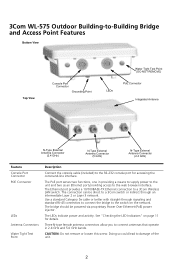
... 3 network. Three N-type female antenna connectors allow you to connect antennas that operate in providing a means to supply power to the unit and two as an Ethernet port providing access to the web browser interface. See "Checking the LED Indicators" on the network. Doing so could lead to a 3Com Wireless LAN switch. The bridge should be direct to a 3Com switch or indirect through signaling and standard RJ-45 connectors to connect the bridge to...
... 3 network. Three N-type female antenna connectors allow you to connect antennas that operate in providing a means to supply power to the unit and two as an Ethernet port providing access to the web browser interface. See "Checking the LED Indicators" on the network. Doing so could lead to a 3Com Wireless LAN switch. The bridge should be direct to a 3Com switch or indirect through signaling and standard RJ-45 connectors to connect the bridge to...
Quick Start Guide
Page 3
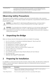
... power injector/ Ethernet connector and AC power cord • One grounding screw, not attached • This Quick Start Guide • One CD-ROM containing the Setup Wizard software and User's Manual • One Warranty Flyer • Optional: One N-type RF coaxial cable 2 Preparing for the country of 20 cm (8 in the package contents. Grounding Point Integrated Antenna In the event of electrostatic shock the connection of...
... power injector/ Ethernet connector and AC power cord • One grounding screw, not attached • This Quick Start Guide • One CD-ROM containing the Setup Wizard software and User's Manual • One Warranty Flyer • Optional: One N-type RF coaxial cable 2 Preparing for the country of 20 cm (8 in the package contents. Grounding Point Integrated Antenna In the event of electrostatic shock the connection of...
Quick Start Guide
Page 4
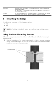
... the V-shaped part of the bracket around the pole during the antenna alignment process.) V-Shaped bracket 4 The PoE injector is for indoor use only. CAUTION: The bridge is intended for indoor use. It is not for outdoor use only. Do not install the bridge indoors. IP Address Location Record the bridge MAC address in a safe place before the bridge is installed in a hard-to be rotated...
... the V-shaped part of the bracket around the pole during the antenna alignment process.) V-Shaped bracket 4 The PoE injector is for indoor use only. CAUTION: The bridge is intended for indoor use. It is not for outdoor use only. Do not install the bridge indoors. IP Address Location Record the bridge MAC address in a safe place before the bridge is installed in a hard-to be rotated...

Quick Start Guide
Page 5
2 Fit the edges of the V-shaped part into the slots in the rectangular plate, and tighten the nuts. Slots 3 Attach the adjustable rectangular plate to the bridge with the supplied screws. 5
2 Fit the edges of the V-shaped part into the slots in the rectangular plate, and tighten the nuts. Slots 3 Attach the adjustable rectangular plate to the bridge with the supplied screws. 5
Quick Start Guide
Page 6
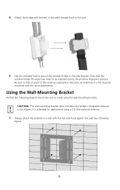
...using a 5.0 GHz external antenna. 1 Always attach the bracket to a wall with the flat side flush against the wall (see following steps to mount the unit to a wall using the wall-mounting bracket: CAUTION: The wall-mounting bracket does not allow the bridge's integrated antenna to the pole bracket. 4 Attach the bridge...aligned. all antennas in a link must be mounted with bracket to the plate already fixed to the pole. 5 Use the included nuts to secure the wireless bridge to be adjusted during the antenna alignment process. Note that the wireless bridge tilt angle may need to take ...
...using a 5.0 GHz external antenna. 1 Always attach the bracket to a wall with the flat side flush against the wall (see following steps to mount the unit to a wall using the wall-mounting bracket: CAUTION: The wall-mounting bracket does not allow the bridge's integrated antenna to the pole bracket. 4 Attach the bridge...aligned. all antennas in a link must be mounted with bracket to the plate already fixed to the pole. 5 Use the included nuts to secure the wireless bridge to be adjusted during the antenna alignment process. Note that the wireless bridge tilt angle may need to take ...
Quick Start Guide
Page 7
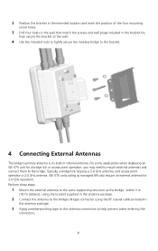
... managed APs also require an external antenna for a bridge link or access point operation, you may need to mount external antennas and connect them to the bridge. WL-575 units acting as the bridge, within 3 m (10 ft) distance, using the bracket supplied in the antenna package. 2 Connect the antenna to the bridge's N-type connector using the RF coaxial cable provided in the antenna package. 3 Apply weatherproofing tape to the antenna connectors to the bracket. 4 Connecting External Antennas...
... managed APs also require an external antenna for a bridge link or access point operation, you may need to mount external antennas and connect them to the bridge. WL-575 units acting as the bridge, within 3 m (10 ft) distance, using the bracket supplied in the antenna package. 2 Connect the antenna to the bridge's N-type connector using the RF coaxial cable provided in the antenna package. 3 Apply weatherproofing tape to the antenna connectors to the bracket. 4 Connecting External Antennas...

Quick Start Guide
Page 8
For additional lightning protection, use the management interface to configure the bridge for correct antenna operation. 2.4 GHz N-type Connector 5 GHz 2.4 GHz N-type Connector N-type Connector 5 GHz External High-gain Panel Antenna RF Coaxial Cable 2.4 GHz External Omnidirectional Antenna 5 Connecting Cables 1 Attach the Ethernet cable to ground the unit with an appropriate grounding wire (not included) by attaching it meets local and national electrical codes. CAUTION: Be sure that grounding is...
For additional lightning protection, use the management interface to configure the bridge for correct antenna operation. 2.4 GHz N-type Connector 5 GHz 2.4 GHz N-type Connector N-type Connector 5 GHz External High-gain Panel Antenna RF Coaxial Cable 2.4 GHz External Omnidirectional Antenna 5 Connecting Cables 1 Attach the Ethernet cable to ground the unit with an appropriate grounding wire (not included) by attaching it meets local and national electrical codes. CAUTION: Be sure that grounding is...
Quick Start Guide
Page 9
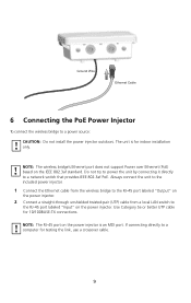
... (UTP) cable from a local LAN switch to a computer for testing the link, use a crossover cable. 9 NOTE: The wireless bridge's Ethernet port does not support Power over Ethernet (PoE) based on the power injector. Use Category 5e or better UTP cable for indoor installation only. The unit is an MDI port. Do not try to power the unit by connecting it directly to a power source: CAUTION: Do not install the power injector outdoors. NOTE: The...
... (UTP) cable from a local LAN switch to a computer for testing the link, use a crossover cable. 9 NOTE: The wireless bridge's Ethernet port does not support Power over Ethernet (PoE) based on the power injector. Use Category 5e or better UTP cable for indoor installation only. The unit is an MDI port. Do not try to power the unit by connecting it directly to a power source: CAUTION: Do not install the power injector outdoors. NOTE: The...
Quick Start Guide
Page 10
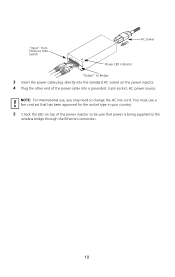
You must use , you may need to change the AC line cord. "Input" from Ethernet Hub/ Switch Input Output AC power Power LED indicator "Output" to the wireless bridge through the Ethernet connection. 10 NOTE: For International use a line cord set that has been approved for the socket type in your country. 5 Check the LED on top of the power injector to be sure that power is being supplied to Bridge 3 Insert the power cable plug directly into the standard AC socket on the power injector. 4 Plug the other end of the power cable into a grounded, 3-pin socket, AC power source.
You must use , you may need to change the AC line cord. "Input" from Ethernet Hub/ Switch Input Output AC power Power LED indicator "Output" to the wireless bridge through the Ethernet connection. 10 NOTE: For International use a line cord set that has been approved for the socket type in your country. 5 Check the LED on top of the power injector to be sure that power is being supplied to Bridge 3 Insert the power cable plug directly into the standard AC socket on the power injector. 4 Plug the other end of the power cable into a grounded, 3-pin socket, AC power source.

Quick Start Guide
Page 11
... use when aligning antennas in two display modes, which are configurable through the software. The system is no activity. The RSSI mode indicates the received signal power and is connected to network activity. The bridge has a 10/100 Mbps Fast Ethernet connection, but there is under cold reset status. Indicates that the bridge is disabled. No link is present or the Ethernet LAN port is transmitting or receiving data on a 10/100 Mbps Ethernet LAN...
... use when aligning antennas in two display modes, which are configurable through the software. The system is no activity. The RSSI mode indicates the received signal power and is connected to network activity. The bridge has a 10/100 Mbps Fast Ethernet connection, but there is under cold reset status. Indicates that the bridge is disabled. No link is present or the Ethernet LAN port is transmitting or receiving data on a 10/100 Mbps Ethernet LAN...
Quick Start Guide
Page 12
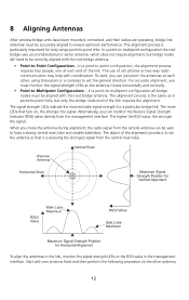
... strongest signal from the management interface. The signal strength LEDs indicate the received radio signal strength for Horizontal Alignment To align the antennas in the link, monitor the signal strength LEDs or the RSSI value in point-to-point links, but bridge nodes still need to ensure optimum performance. The more LEDs that turn on the other , using binoculars or a compass to set the antenna so that it is to -point configuration, the...
... strongest signal from the management interface. The signal strength LEDs indicate the received radio signal strength for Horizontal Alignment To align the antennas in the link, monitor the signal strength LEDs or the RSSI value in point-to-point links, but bridge nodes still need to ensure optimum performance. The more LEDs that turn on the other , using binoculars or a compass to set the antenna so that it is to -point configuration, the...
Quick Start Guide
Page 13
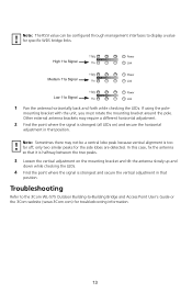
... using the pole- Note: The RSSI value can be a central lobe peak because vertical alignment is too far off; only two similar peaks for troubleshooting information. 13 mounting bracket with the unit, you must rotate the mounting bracket around the pole. Other external antenna brackets may not be configured through management interfaces to -Building Bridge and Access Point User's Guide or the 3Com website...
... using the pole- Note: The RSSI value can be a central lobe peak because vertical alignment is too far off; only two similar peaks for troubleshooting information. 13 mounting bracket with the unit, you must rotate the mounting bracket around the pole. Other external antenna brackets may not be configured through management interfaces to -Building Bridge and Access Point User's Guide or the 3Com website...
Quick Start Guide
Page 14
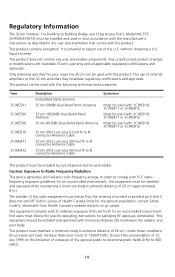
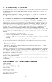
... or 3CWE812. This product must maintain a minimum body to Radio Frequency Radiation This device generates and radiates radio-frequency energy. Regulatory Information The 3Com Outdoor 11a Building to Building Bridge and 11bg Access Point, Model WL-575 (3CRWEASYA73) must be installed and used in strict accordance with the manufacturer's instructions as described in the user documentation that the antenna is unlawful to export out of the U.S. Only...
... or 3CWE812. This product must maintain a minimum body to Radio Frequency Radiation This device generates and radiates radio-frequency energy. Regulatory Information The 3Com Outdoor 11a Building to Building Bridge and 11bg Access Point, Model WL-575 (3CRWEASYA73) must be installed and used in strict accordance with the manufacturer's instructions as described in the user documentation that the antenna is unlawful to export out of the U.S. Only...
Quick Start Guide
Page 15
... by 3Com. This device is connected. • Consult the dealer or an experienced radio/TV technician for a Class B digital device, pursuant to 5.25 GHz frequency range. These limits are allocated as primary users of the following booklet prepared by 3Com could void the user's authority to 5.85 GHz bands. The user may cause harmful interference to Building Bridge and 11bg Access Point, Model WL-575 (3CRWEASYA73...
... by 3Com. This device is connected. • Consult the dealer or an experienced radio/TV technician for a Class B digital device, pursuant to 5.25 GHz frequency range. These limits are allocated as primary users of the following booklet prepared by 3Com could void the user's authority to 5.85 GHz bands. The user may cause harmful interference to Building Bridge and 11bg Access Point, Model WL-575 (3CRWEASYA73...

Quick Start Guide
Page 16
... (2) this device. Equipment Type: 3Com Outdoor 11a Building to these or other antenna or transmitter. To reduce potential radio interference to provide maximum shielding. To prevent radio interference to the licensed service, this device is not more than that the equivalent isotropically radiated power (EIRP) is intended to be operated indoors and away from windows to other users, the antenna type and its transmit antenna) that may...
... (2) this device. Equipment Type: 3Com Outdoor 11a Building to these or other antenna or transmitter. To reduce potential radio interference to provide maximum shielding. To prevent radio interference to the licensed service, this device is not more than that the equivalent isotropically radiated power (EIRP) is intended to be operated indoors and away from windows to other users, the antenna type and its transmit antenna) that may...

Quick Start Guide
Page 17
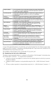
Refer to installation instructions. Česky [Czech] Dansk [Danish] Deutsch [German] Eesti [Estonian] Englis h Español [Spanish Greek] Français [French] 3Co m Co poration tímto prohlašuje, že tento RLAN device je v e shodě se základními požadav ky a dalšími pří... GR HU IE IT LV LT LU MT NL PL PT SK SI ES SE GB IS LI NO CH BG RO TR Intended use: IEEE 802.11b/g/a radio LAN device NOTE: To ensure product operation is in compliance with the essential requirements and other relev ant prov isions of Directiv e 1999/5/EC. ...
Refer to installation instructions. Česky [Czech] Dansk [Danish] Deutsch [German] Eesti [Estonian] Englis h Español [Spanish Greek] Français [French] 3Co m Co poration tímto prohlašuje, že tento RLAN device je v e shodě se základními požadav ky a dalšími pří... GR HU IE IT LV LT LU MT NL PL PT SK SI ES SE GB IS LI NO CH BG RO TR Intended use: IEEE 802.11b/g/a radio LAN device NOTE: To ensure product operation is in compliance with the essential requirements and other relev ant prov isions of Directiv e 1999/5/EC. ...
Quick Start Guide
Page 18
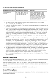
... direttiv a 1999/5/CE. Restrictions for the 3Com Outdoor 11a Building to Building Bridge and 11bg Access Point, Model WL-575 (3CRWEASYA73) at http://support.3com.com/doc/WL-575_EU_DOC.pdf EU - Hierbij v erklaart 3Co m Corpo ration dat het toestel RLAN device in muiden ehtojen mukainen. A copy of the signed Declaration of the European Community using the 2.4 - 2.454 GHz band: Channels 1 - 7. 18 Also available at http...
... direttiv a 1999/5/CE. Restrictions for the 3Com Outdoor 11a Building to Building Bridge and 11bg Access Point, Model WL-575 (3CRWEASYA73) at http://support.3com.com/doc/WL-575_EU_DOC.pdf EU - Hierbij v erklaart 3Co m Corpo ration dat het toestel RLAN device in muiden ehtojen mukainen. A copy of the signed Declaration of the European Community using the 2.4 - 2.454 GHz band: Channels 1 - 7. 18 Also available at http...
Quick Start Guide
Page 19
...; In Italy the end-user must be necessary to operate this device. You may result in temporary interruption in communications of the allowable frequencies as listed above 5GHz channel limitations apply. The Bridge/Access Point's radar detection feature will automatically restart operation on another channel. • Ad-hoc mode provides a direct communication between two client devices without a Wireless LAN Access Point. This feature must apply...
...; In Italy the end-user must be necessary to operate this device. You may result in temporary interruption in communications of the allowable frequencies as listed above 5GHz channel limitations apply. The Bridge/Access Point's radar detection feature will automatically restart operation on another channel. • Ad-hoc mode provides a direct communication between two client devices without a Wireless LAN Access Point. This feature must apply...

Quick Start Guide
Page 20
... 3Com logo are associated. Part Number:1100001165523371, Revision AA Published December, 2007 All other company and product names may be trademarks of the respective companies with which they are registered trademarks of 3Com Corporation. Safety Information AC Power Adapter • Input: 100-240 AC, 50-60 Hz • Output: 48 VDC, 1.2 A • Power consumption: 13.2 watts Unit Power Supply...
... 3Com logo are associated. Part Number:1100001165523371, Revision AA Published December, 2007 All other company and product names may be trademarks of the respective companies with which they are registered trademarks of 3Com Corporation. Safety Information AC Power Adapter • Input: 100-240 AC, 50-60 Hz • Output: 48 VDC, 1.2 A • Power consumption: 13.2 watts Unit Power Supply...


