Quick Start Guide
Page 1
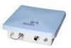
...Antennas • Troubleshooting Quick Start Guide 3Com Wireless 802.11a Outdoor Building-to-Building Bridge and Access Point 3CRWEASYA73 / WL-575 The 3Com WL-575 802.11a Outdoor Building-to-Building Bridge and Access Point provides IEEE 802.11a or 802.11b/g wireless access to an isolated site. Power ...covers the following topics: • 3Com WL-575 Outdoor Building-to-Building Bridge and Access Point • Observing Safety Precautions • Step 1: Unpacking the Bridge • Step 2: Preparing for connectivity between remote Ethernet wired LANs or to provide Internet access to the...
...Antennas • Troubleshooting Quick Start Guide 3Com Wireless 802.11a Outdoor Building-to-Building Bridge and Access Point 3CRWEASYA73 / WL-575 The 3Com WL-575 802.11a Outdoor Building-to-Building Bridge and Access Point provides IEEE 802.11a or 802.11b/g wireless access to an isolated site. Power ...covers the following topics: • 3Com WL-575 Outdoor Building-to-Building Bridge and Access Point • Observing Safety Precautions • Step 1: Unpacking the Bridge • Step 2: Preparing for connectivity between remote Ethernet wired LANs or to provide Internet access to the...
Quick Start Guide
Page 2
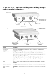
...the bridge to the RS-232 console port for details. See "Checking the LED Indicators" on the network. Doing so could lead to a 3Com Wireless LAN switch. The PoE port serves two functions, one in providing a means to supply power to the unit and two as an Ethernet port providing... remove or loosen this screw. Use a standard Category 5e cable or better with straight-through an intermediate Layer 2 or Layer 3 network. 3Com WL-575 Outdoor Building-to-Building Bridge and Access Point Features Bottom View Top View Console Port Connector Grounding Point LEDs Water Tight Test Point (DO NOT...
...the bridge to the RS-232 console port for details. See "Checking the LED Indicators" on the network. Doing so could lead to a 3Com Wireless LAN switch. The PoE port serves two functions, one in providing a means to supply power to the unit and two as an Ethernet port providing... remove or loosen this screw. Use a standard Category 5e cable or better with straight-through an intermediate Layer 2 or Layer 3 network. 3Com WL-575 Outdoor Building-to-Building Bridge and Access Point Features Bottom View Top View Console Port Connector Grounding Point LEDs Water Tight Test Point (DO NOT...
Quick Start Guide
Page 3
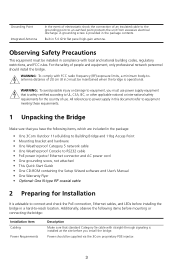
... bridge is operational. For the safety of use power supply equipment that you have the following items, which are included in the package: • One 3Com Outdoor 11a Building to Building Bridge and 11bg Access Point • Mounting bracket and hardware • One Weatherproof Category 5 network cable • One Weatherproof Console to RS232... restrictions, and FCC rules. Grounding Point Integrated Antenna In the event of electrostatic shock the connection of 20 cm (8 in.) must be supplied via the 3Com proprietary POE injector. 3
... bridge is operational. For the safety of use power supply equipment that you have the following items, which are included in the package: • One 3Com Outdoor 11a Building to Building Bridge and 11bg Access Point • Mounting bracket and hardware • One Weatherproof Category 5 network cable • One Weatherproof Console to RS232... restrictions, and FCC rules. Grounding Point Integrated Antenna In the event of electrostatic shock the connection of 20 cm (8 in.) must be supplied via the 3Com proprietary POE injector. 3
Quick Start Guide
Page 4
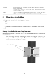
... the pole and tighten the securing nuts just enough to hold the bracket to the pole. (The bracket may need to be installed outdoors. It is intended for outdoor use only. Plan your equipment location accordingly. 3 Mounting the Bridge The bridge can be mounted on the back of the bridge. Do not...
... the pole and tighten the securing nuts just enough to hold the bracket to the pole. (The bracket may need to be installed outdoors. It is intended for outdoor use only. Plan your equipment location accordingly. 3 Mounting the Bridge The bridge can be mounted on the back of the bridge. Do not...

Quick Start Guide
Page 5
2 Fit the edges of the V-shaped part into the slots in the rectangular plate, and tighten the nuts. Slots 3 Attach the adjustable rectangular plate to the bridge with the supplied screws. 5
2 Fit the edges of the V-shaped part into the slots in the rectangular plate, and tighten the nuts. Slots 3 Attach the adjustable rectangular plate to the bridge with the supplied screws. 5
Quick Start Guide
Page 6
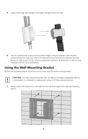
... Perform the following steps to mount the unit to a wall using a 5.0 GHz external antenna. 1 Always attach the bracket to the pole bracket. Note that the wireless bridge tilt angle may need to take account of the antenna polarization direction; Be sure to be adjusted during the antenna alignment process. It is... the wall (see following figure). 6 4 Attach the bridge with bracket to the plate already fixed to the pole. 5 Use the included nuts to secure the wireless bridge to a wall with the same polarization.
... Perform the following steps to mount the unit to a wall using a 5.0 GHz external antenna. 1 Always attach the bracket to the pole bracket. Note that the wireless bridge tilt angle may need to take account of the antenna polarization direction; Be sure to be adjusted during the antenna alignment process. It is... the wall (see following figure). 6 4 Attach the bridge with bracket to the plate already fixed to the pole. 5 Use the included nuts to secure the wireless bridge to a wall with the same polarization.
Quick Start Guide
Page 7
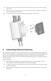
... the screws and wall plugs included in the bracket kit, then secure the bracket to the wall. 4 Use the included nuts to tightly secure the wireless bridge to the bracket. 4 Connecting External Antennas The bridge's primary antenna is it's built-in the antenna package. 3 Apply weatherproofing tape to the antenna connectors...
... the screws and wall plugs included in the bracket kit, then secure the bracket to the wall. 4 Use the included nuts to tightly secure the wireless bridge to the bracket. 4 Connecting External Antennas The bridge's primary antenna is it's built-in the antenna package. 3 Apply weatherproofing tape to the antenna connectors...

Quick Start Guide
Page 8
CAUTION: Be sure that grounding is available and that it to the grounding screw on the wireless bridge. 2 For extra protection against rain or moisture, apply weatherproofing tape (not included) around the Ethernet connector. 3 Be sure to ground the unit with an ...
CAUTION: Be sure that grounding is available and that it to the grounding screw on the wireless bridge. 2 For extra protection against rain or moisture, apply weatherproofing tape (not included) around the Ethernet connector. 3 Be sure to ground the unit with an ...
Quick Start Guide
Page 9
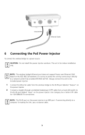
...to the RJ-45 port labeled "Input" on the power injector. 2 Connect a straight-through unshielded twisted-pair (UTP) cable from the wireless bridge to the RJ-45 port labeled "Output" on the power injector. Always connect the unit to the included power injector. 1 Connect the... Ethernet cable from a local LAN switch to a network switch that provides IEEE 802.3af PoE. If connecting directly to a power source: CAUTION: Do not install the power injector outdoors. Ground Wire Ethernet Cable 6 Connecting the PoE Power Injector To connect the wireless bridge to a computer for testing ...
...to the RJ-45 port labeled "Input" on the power injector. 2 Connect a straight-through unshielded twisted-pair (UTP) cable from the wireless bridge to the RJ-45 port labeled "Output" on the power injector. Always connect the unit to the included power injector. 1 Connect the... Ethernet cable from a local LAN switch to a network switch that provides IEEE 802.3af PoE. If connecting directly to a power source: CAUTION: Do not install the power injector outdoors. Ground Wire Ethernet Cable 6 Connecting the PoE Power Injector To connect the wireless bridge to a computer for testing ...
Quick Start Guide
Page 10
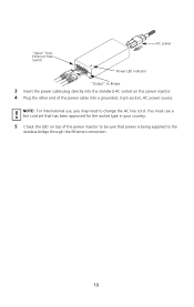
You must use , you may need to change the AC line cord. NOTE: For International use a line cord set that power is being supplied to the wireless bridge through the Ethernet connection. 10 "Input" from Ethernet Hub/ Switch Input Output AC power Power LED indicator "Output" to Bridge 3 Insert the power cable plug directly into the standard AC socket on top of the power injector to be sure that has been approved for the socket type in your country. 5 Check the LED on the power injector. 4 Plug the other end of the power cable into a grounded, 3-pin socket, AC power source.
You must use , you may need to change the AC line cord. NOTE: For International use a line cord set that power is being supplied to the wireless bridge through the Ethernet connection. 10 "Input" from Ethernet Hub/ Switch Input Output AC power Power LED indicator "Output" to Bridge 3 Insert the power cable plug directly into the standard AC socket on top of the power injector to be sure that has been approved for the socket type in your country. 5 Check the LED on the power injector. 4 Plug the other end of the power cable into a grounded, 3-pin socket, AC power source.

Quick Start Guide
Page 11
... there is transmitting or receiving data on a 10/100 Mbps Ethernet LAN. Indicates that the bridge is no activity. The 802.11g 2.4 GHz radio is powered up and operating normally. When the bridge is connected to network activity. Flashing rate is enabled. The 802.11a 5.3 GHz radio is proportional to power, LEDs indicate...
... there is transmitting or receiving data on a 10/100 Mbps Ethernet LAN. Indicates that the bridge is no activity. The 802.11g 2.4 GHz radio is powered up and operating normally. When the bridge is connected to network activity. Flashing rate is enabled. The 802.11a 5.3 GHz radio is proportional to power, LEDs indicate...
Quick Start Guide
Page 12
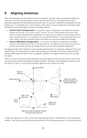
..., you must be correctly aligned with the root bridge antenna. The more LEDs that it is particularly important for a particular bridge link. 8 Aligning Antennas After wireless bridge units have a strong central main lobe and smaller side lobes. In a point-to-point configuration, the alignment process requires two people, one antenna fixed...
..., you must be correctly aligned with the root bridge antenna. The more LEDs that it is particularly important for a particular bridge link. 8 Aligning Antennas After wireless bridge units have a strong central main lobe and smaller side lobes. In a point-to-point configuration, the alignment process requires two people, one antenna fixed...
Quick Start Guide
Page 13
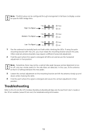
...the side lobes are detected. Troubleshooting Refer to the 3Com WL-575 Outdoor Building-to display a value for specific WDS bridge links. 11b/g High 11a Signal 11a Power Link 11b/g Medium 11a Signal 11a Power Link 11b/g Low 11a Signal 11a Power Link 1 Pan the antenna horizontally back and ...Other external antenna brackets may not be configured through management interfaces to -Building Bridge and Access Point User's Guide or the 3Com website (www.3Com.com) for troubleshooting information. 13 If using the pole- Note: The RSSI value can be a central lobe peak because...
...the side lobes are detected. Troubleshooting Refer to the 3Com WL-575 Outdoor Building-to display a value for specific WDS bridge links. 11b/g High 11a Signal 11a Power Link 11b/g Medium 11a Signal 11a Power Link 11b/g Low 11a Signal 11a Power Link 1 Pan the antenna horizontally back and ...Other external antenna brackets may not be configured through management interfaces to -Building Bridge and Access Point User's Guide or the 3Com website (www.3Com.com) for troubleshooting information. 13 If using the pole- Note: The RSSI value can be a central lobe peak because...
Quick Start Guide
Page 14
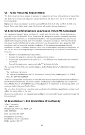
... of 1999/519/EC [Council Recommendation of 12 July 1999 on the limitation of exposure of external amplifiers or non-3Com antennas may invalidate regulatory certifications and approvals. Only antennas specified for your body. This equipment should be used with FCC... equipment complies with 3CWE810, 3CWE811 or 3CWE812. The installer of the U.S. Regulatory Information The 3Com Outdoor 11a Building to Building Bridge and 11bg Access Point, Model WL-575 (3CRWEASYA73) must follow the specific operating instructions for satisfying RF exposure compliance. The use of the general...
... of 1999/519/EC [Council Recommendation of 12 July 1999 on the limitation of exposure of external amplifiers or non-3Com antennas may invalidate regulatory certifications and approvals. Only antennas specified for your body. This equipment should be used with FCC... equipment complies with 3CWE810, 3CWE811 or 3CWE812. The installer of the U.S. Regulatory Information The 3Com Outdoor 11a Building to Building Bridge and 11bg Access Point, Model WL-575 (3CRWEASYA73) must follow the specific operating instructions for satisfying RF exposure compliance. The use of the general...
Quick Start Guide
Page 15
... to try to correct the interference by one or more of the following booklet prepared by 3Com could void the user's authority to operate this 3Com Outdoor 11a Building to Building Bridge and 11bg Access Point, Model WL-575 (3CRWEASYA73), or the substitution or attachment of connecting cables and equipment other antenna or transmitter. The...
... to try to correct the interference by one or more of the following booklet prepared by 3Com could void the user's authority to operate this 3Com Outdoor 11a Building to Building Bridge and 11bg Access Point, Model WL-575 (3CRWEASYA73), or the substitution or attachment of connecting cables and equipment other antenna or transmitter. The...

Quick Start Guide
Page 16
... has been tested and certified according to the following safety standards and is not more than that may cause undesired operation. 3Com Outdoor 11a Building to Building Bridge and 11bg Access Point Model WL-575 Industry Canada - Equipment (or its gain should be operated ...accepter tout brouillage radioélectrique reçu, même si ce brouillage est susceptible de compromettre le fonctionnement du dispositif. Equipment Type: 3Com Outdoor 11a Building to Building Bridge and 11bg Access Point Complies with RSS 210 of Industry Canada. Si le matriel (ou son antenne d'emission) ...
... has been tested and certified according to the following safety standards and is not more than that may cause undesired operation. 3Com Outdoor 11a Building to Building Bridge and 11bg Access Point Model WL-575 Industry Canada - Equipment (or its gain should be operated ...accepter tout brouillage radioélectrique reçu, même si ce brouillage est susceptible de compromettre le fonctionnement du dispositif. Equipment Type: 3Com Outdoor 11a Building to Building Bridge and 11bg Access Point Complies with RSS 210 of Industry Canada. Si le matriel (ou son antenne d'emission) ...

Quick Start Guide
Page 17
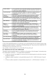
... LV LT LU MT NL PL PT SK SI ES SE GB IS LI NO CH BG RO TR Intended use: IEEE 802.11b/g/a radio LAN device NOTE: To ensure product operation is in compliance with the essential requirements and other relev ant prov isions of Directiv e 1999/5/EC.
... LV LT LU MT NL PL PT SK SI ES SE GB IS LI NO CH BG RO TR Intended use: IEEE 802.11b/g/a radio LAN device NOTE: To ensure product operation is in compliance with the essential requirements and other relev ant prov isions of Directiv e 1999/5/EC.
Quick Start Guide
Page 18
...band: Channels 1 - 13, except where noted below. • In Italy the end-user must apply for the 3Com Outdoor 11a Building to Building Bridge and 11bg Access Point, Model WL-575 (3CRWEASYA73) at http://support.3com.com/doc/WL-575_EU_DOC.pdf EU - Niniejszy m 3Co m Corp oration oświa dcza, że RLA N ...de andere relev ante bepaling en v an richtlijn 1999/5/EG. Also available at http://www.3com.com. Restrictions for Use in the 2.4GHz band This device may be operated indoors or outdoors in all countries of Conformity can be downloaded from the Product Support web page for a license...
...band: Channels 1 - 13, except where noted below. • In Italy the end-user must apply for the 3Com Outdoor 11a Building to Building Bridge and 11bg Access Point, Model WL-575 (3CRWEASYA73) at http://support.3com.com/doc/WL-575_EU_DOC.pdf EU - Niniejszy m 3Co m Corp oration oświa dcza, że RLA N ...de andere relev ante bepaling en v an richtlijn 1999/5/EG. Also available at http://www.3com.com. Restrictions for Use in the 2.4GHz band This device may be operated indoors or outdoors in all countries of Conformity can be downloaded from the Product Support web page for a license...
Quick Start Guide
Page 19
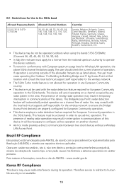
...activated in order to configure ad-hoc operation on another channel. • Ad-hoc mode provides a direct communication between two client devices without a Wireless LAN Access Point. Para maiores informações, consulte o site da ANATEL - The user should check the current channel of this device. You...-5350MHz (Channels 36, 40, 44, 48, 52, 56, 50, 64). • In Italy the end-user must cease operating the Outdoor 11a Building to operate this device. The presence of nearby radar operation may result in interruption in the area. The Bridge/Access Point's radar detection ...
...activated in order to configure ad-hoc operation on another channel. • Ad-hoc mode provides a direct communication between two client devices without a Wireless LAN Access Point. Para maiores informações, consulte o site da ANATEL - The user should check the current channel of this device. You...-5350MHz (Channels 36, 40, 44, 48, 52, 56, 50, 64). • In Italy the end-user must cease operating the Outdoor 11a Building to operate this device. The presence of nearby radar operation may result in interruption in the area. The Bridge/Access Point's radar detection ...

Quick Start Guide
Page 20
All other company and product names may be trademarks of 3Com Corporation. All rights reserved. 3Com and the 3Com logo are registered trademarks of the respective companies with which they are associated. Safety Information AC Power Adapter • Input: 100-240 AC, 50-... • PoE input: 48 VDC, 0.6 A maximum • Power consumption: 28 watts maximum Physical Size • 19.5 x 19 x 7.4 cm (7.68 x 7.48 x 2.91 in) Weight • 1.54 kg (3.4 lbs) Temperature • Operating: -40 to 60°C (-40 to 140°F) non-condensing @ 5 to 50°C • Storage: -55 to 80°C (-67...
All other company and product names may be trademarks of 3Com Corporation. All rights reserved. 3Com and the 3Com logo are registered trademarks of the respective companies with which they are associated. Safety Information AC Power Adapter • Input: 100-240 AC, 50-... • PoE input: 48 VDC, 0.6 A maximum • Power consumption: 28 watts maximum Physical Size • 19.5 x 19 x 7.4 cm (7.68 x 7.48 x 2.91 in) Weight • 1.54 kg (3.4 lbs) Temperature • Operating: -40 to 60°C (-40 to 140°F) non-condensing @ 5 to 50°C • Storage: -55 to 80°C (-67...