
Getting Started Guide
Page 3
Rear View Detail 23 Switch 5500 23 Switch 5500G-EI 24 Expansion Module Slot 24 Power Socket 24 Open Book Warning Labels 24 Redundant Power System Socket 25 Stacking Cable Ports (Switch 5500G-EI) 25 CONTENTS ABOUT THIS GUIDE Before You Start 9 Release Notes ... Related Documentation 11 Accessing Online Documentation 11 Documentation Comments 12 1 INTRODUCING THE SUPERSTACK 4 SWITCH 5500 FAMILY About the Switch 5500 Family 14 Summary of Hardware Features 15 Switch 5500 Family - Front View Detail 16 Switch 5500 16 Switch 5500G-EI 17 10BASE-T/ 100BASE-TX/ 1000BASE-T Ports 18 1000BASE-X SFP Ports...
Rear View Detail 23 Switch 5500 23 Switch 5500G-EI 24 Expansion Module Slot 24 Power Socket 24 Open Book Warning Labels 24 Redundant Power System Socket 25 Stacking Cable Ports (Switch 5500G-EI) 25 CONTENTS ABOUT THIS GUIDE Before You Start 9 Release Notes ... Related Documentation 11 Accessing Online Documentation 11 Documentation Comments 12 1 INTRODUCING THE SUPERSTACK 4 SWITCH 5500 FAMILY About the Switch 5500 Family 14 Summary of Hardware Features 15 Switch 5500 Family - Front View Detail 16 Switch 5500 16 Switch 5500G-EI 17 10BASE-T/ 100BASE-TX/ 1000BASE-T Ports 18 1000BASE-X SFP Ports...

Getting Started Guide
Page 9
... (Local Area Networks). consequently, it assumes a basic working knowledge of other useful applications. Before You Start This section contains information about the Switch 5500 - refer to -use 3Com® SuperStack® 4 Switch 5500 in Adobe Acrobat Reader Portable Document Format (PDF) or HTML on page 11 for installing and setting up network equipment; a powerful and easy...
... (Local Area Networks). consequently, it assumes a basic working knowledge of other useful applications. Before You Start This section contains information about the Switch 5500 - refer to -use 3Com® SuperStack® 4 Switch 5500 in Adobe Acrobat Reader Portable Document Format (PDF) or HTML on page 11 for installing and setting up network equipment; a powerful and easy...

Getting Started Guide
Page 11
...is also supplied under the Help button on the web interface. ■ SuperStack 4 Switch 5500 Configuration Guide This guide contains information on the CD-ROM that accompanies your Switch. ■ SuperStack 4 Switch 5500 Command Reference Guide This guide contains detailed information about the web interface and...the CLI This guide contains: ■ a list of the features supported by your Switch, Documentation do the following : ■ SuperStack 4 Switch 5500 Quick Reference Guide for the Switch. It is to be accessed from the contents page. Accessing Online To access the ...
...is also supplied under the Help button on the web interface. ■ SuperStack 4 Switch 5500 Configuration Guide This guide contains information on the CD-ROM that accompanies your Switch. ■ SuperStack 4 Switch 5500 Command Reference Guide This guide contains detailed information about the web interface and...the CLI This guide contains: ■ a list of the features supported by your Switch, Documentation do the following : ■ SuperStack 4 Switch 5500 Quick Reference Guide for the Switch. It is to be accessed from the contents page. Accessing Online To access the ...

Getting Started Guide
Page 12
Your suggestions are very important to you. Example: Part Number DUA1725-0AAA01 3Com SuperStack 4 Switch 5500 Getting Started Guide Page 21 Please note that we can only respond to comments and questions about this e-mail address. Questions related ... directed in the Docs/configuration directory on the title page) and Page number (if appropriate). Please e-mail comments about 3Com product documentation at this document to 3Com at: pddtechpubs_comments@3com.com Please include the following information when commenting: Document title, Document part number (on the CD-ROM. They will ...
Your suggestions are very important to you. Example: Part Number DUA1725-0AAA01 3Com SuperStack 4 Switch 5500 Getting Started Guide Page 21 Please note that we can only respond to comments and questions about this e-mail address. Questions related ... directed in the Docs/configuration directory on the title page) and Page number (if appropriate). Please e-mail comments about 3Com product documentation at this document to 3Com at: pddtechpubs_comments@3com.com Please include the following information when commenting: Document title, Document part number (on the CD-ROM. They will ...

Getting Started Guide
Page 13
Front View Detail ■ Switch 5500 Family - It covers summary information about the Switch 5500 Family and how they can be used in your network. Rear View Detail ■ Default Settings 1 INTRODUCING THE SUPERSTACK 4 SWITCH 5500 FAMILY This chapter contains introductory information about the hardware and the following topics: ■ About the Switch 5500 Family ■ Switch 5500 Family -
Front View Detail ■ Switch 5500 Family - It covers summary information about the Switch 5500 Family and how they can be used in your network. Rear View Detail ■ Default Settings 1 INTRODUCING THE SUPERSTACK 4 SWITCH 5500 FAMILY This chapter contains introductory information about the hardware and the following topics: ■ About the Switch 5500 Family ■ Switch 5500 Family -

Getting Started Guide
Page 14
... Slot Switch 5500 Family Switch 5500-SI 28 Port 24 4 11 Switch 5500-SI 52 Port 48 4 11 Switch 5500-EI 28 Port 24 4 11 Switch 5500-EI 52 Port 48 4 11 Switch 5500 PWR 28 Port 24 4 11 Switch 5500 PWR 52 Port 48 4 11 Switch 5500 FX 28 Port 2 24 2 11 Switch 5500G-EI... 10/100/100 Ports For information about using the software features of the Switch, refer to the "Command Reference Guide" on the CD-ROM that accompanies the Switch. 14 CHAPTER 1: INTRODUCING THE SUPERSTACK 4 SWITCH 5500 FAMILY About the Switch 5500 Family The Switch 5500 Family are mixed media devices.
... Slot Switch 5500 Family Switch 5500-SI 28 Port 24 4 11 Switch 5500-SI 52 Port 48 4 11 Switch 5500-EI 28 Port 24 4 11 Switch 5500-EI 52 Port 48 4 11 Switch 5500 PWR 28 Port 24 4 11 Switch 5500 PWR 52 Port 48 4 11 Switch 5500 FX 28 Port 2 24 2 11 Switch 5500G-EI... 10/100/100 Ports For information about using the software features of the Switch, refer to the "Command Reference Guide" on the CD-ROM that accompanies the Switch. 14 CHAPTER 1: INTRODUCING THE SUPERSTACK 4 SWITCH 5500 FAMILY About the Switch 5500 Family The Switch 5500 Family are mixed media devices.

Getting Started Guide
Page 16
front view PWR LED 1000BASE-X Ports Port Status LEDs Console Port RPS LED 3CR17171-91 SuperStack 4 Switch 5500 PWR 28 Port Green=Status Yellow=Packet Red=PoE 10/100BASE-TX Ports 1000BASE-X Ports Unit LED Mode LED Power LED ... Unit LED Mode LED Power LED Figure 2 Switch 5500 SI and EI 52-Port - front view Port Status LEDs Console Port Unit LED RPS LED Mode LED 10/100BASE-TX Ports Figure 3 Switch 5500-EI 28-Port PWR - Front View Detail Switch 5500 Figure 1 Switch 5500 SI and EI 28-Port - 16 CHAPTER 1: INTRODUCING THE SUPERSTACK 4 SWITCH 5500 FAMILY Switch 5500 Family -
front view PWR LED 1000BASE-X Ports Port Status LEDs Console Port RPS LED 3CR17171-91 SuperStack 4 Switch 5500 PWR 28 Port Green=Status Yellow=Packet Red=PoE 10/100BASE-TX Ports 1000BASE-X Ports Unit LED Mode LED Power LED ... Unit LED Mode LED Power LED Figure 2 Switch 5500 SI and EI 52-Port - front view Port Status LEDs Console Port Unit LED RPS LED Mode LED 10/100BASE-TX Ports Figure 3 Switch 5500-EI 28-Port PWR - Front View Detail Switch 5500 Figure 1 Switch 5500 SI and EI 28-Port - 16 CHAPTER 1: INTRODUCING THE SUPERSTACK 4 SWITCH 5500 FAMILY Switch 5500 Family -

Getting Started Guide
Page 17
... Port Status LEDs Console Port Unit LED RPS LED Mode LED 3CR17172-91 SuperStack 4 Switch 5500 PWR 52 Port Green=Status Yellow=Packet Red=PoE 10/100BASE-TX Ports Figure 5 Switch 5500-EI FX 28-Port - Front View Detail 17 Figure 4 Switch 5500-EI 52-Port PWR - front view PWR LED 1000BASE-X Ports Port Status... LEDs Speed Duplex Console Port RPS LED 3CR17181-91 SuperStack 4 Switch 5500-EI 28-Port FX 100Base-FX 1000Base-X 10/100/100BASE-T Green=Speed Yellow=Duplex RPS PWR 100BASE-FX Ports 1000BASE-X Ports Unit LED...
... Port Status LEDs Console Port Unit LED RPS LED Mode LED 3CR17172-91 SuperStack 4 Switch 5500 PWR 52 Port Green=Status Yellow=Packet Red=PoE 10/100BASE-TX Ports Figure 5 Switch 5500-EI FX 28-Port - Front View Detail 17 Figure 4 Switch 5500-EI 52-Port PWR - front view PWR LED 1000BASE-X Ports Port Status... LEDs Speed Duplex Console Port RPS LED 3CR17181-91 SuperStack 4 Switch 5500-EI 28-Port FX 100Base-FX 1000Base-X 10/100/100BASE-T Green=Speed Yellow=Duplex RPS PWR 100BASE-FX Ports 1000BASE-X Ports Unit LED...

Getting Started Guide
Page 18
...10BASE-T/100BASE-TX/1000BASE-T ports have RJ-45 connectors and 100BASE-TX/ are shielded RJ-45 data sockets. 18 CHAPTER 1: INTRODUCING THE SUPERSTACK 4 SWITCH 5500 FAMILY Figure 7 Switch 5500G-EI (48 port) - front view Port Status LEDs Console Port Unit LED Status:Green=10Mbps Yellow=10Mbps Flashing=Disabled Packet:Green=...=1000Mbps Yellow=10/100Mbps D(Duplex):Green=Full Duplex Yellow=Half Duplex 1000Base-X 1000Base-X Power LED RPS LED 25/11 SD 3CR17259-91 SuperStack 4 Switch 5500G-EI SFP 24-Port 26/12 SD 27/23 SD 28/24 SD 10/100/1000Base-TX PWR RPS STK MOD 1000BASE-X ...
...10BASE-T/100BASE-TX/1000BASE-T ports have RJ-45 connectors and 100BASE-TX/ are shielded RJ-45 data sockets. 18 CHAPTER 1: INTRODUCING THE SUPERSTACK 4 SWITCH 5500 FAMILY Figure 7 Switch 5500G-EI (48 port) - front view Port Status LEDs Console Port Unit LED Status:Green=10Mbps Yellow=10Mbps Flashing=Disabled Packet:Green=...=1000Mbps Yellow=10/100Mbps D(Duplex):Green=Full Duplex Yellow=Half Duplex 1000Base-X 1000Base-X Power LED RPS LED 25/11 SD 3CR17259-91 SuperStack 4 Switch 5500G-EI SFP 24-Port 26/12 SD 27/23 SD 28/24 SD 10/100/1000Base-TX PWR RPS STK MOD 1000BASE-X ...

Getting Started Guide
Page 20
... failed POST. For information on using the LEDs for problem solving, see "Solving Problems Indicated by LEDs" on the front of the Switch, and how to read their status according to diagnose hardware faults, display POST test ID, display Stack ID, display PoE utilization and ...failed POST. Yellow A low speed (10 Mbps) link is present, blinking off for every packet received or transmitted. 20 CHAPTER 1: INTRODUCING THE SUPERSTACK 4 SWITCH 5500 FAMILY Unit LED The Unit LED is present. Yellow flashing The port has failed post. Yellow A low speed (10/100 Mbps) link is ...
... failed POST. For information on using the LEDs for problem solving, see "Solving Problems Indicated by LEDs" on the front of the Switch, and how to read their status according to diagnose hardware faults, display POST test ID, display Stack ID, display PoE utilization and ...failed POST. Yellow A low speed (10 Mbps) link is present, blinking off for every packet received or transmitted. 20 CHAPTER 1: INTRODUCING THE SUPERSTACK 4 SWITCH 5500 FAMILY Unit LED The Unit LED is present. Yellow flashing The port has failed post. Yellow A low speed (10/100 Mbps) link is ...

Getting Started Guide
Page 22
...Green 10/100/1000 Port Speed and Activity, 1000 SFP Status and Activity, or Stack Status and Activity. 22 CHAPTER 1: INTRODUCING THE SUPERSTACK 4 SWITCH 5500 FAMILY LED Color Indicates Unit LED Green Power on Self Test (POST) is in progress. During POST a test ID number appears in... the Unit LED (seven segment display) or Software download is no RPS supply connected. Green flashing 't' The Switch is over temperature and unit temperature is installed and operating normally. Stack LED Green The XRN stack is functioning without the loop connection....
...Green 10/100/1000 Port Speed and Activity, 1000 SFP Status and Activity, or Stack Status and Activity. 22 CHAPTER 1: INTRODUCING THE SUPERSTACK 4 SWITCH 5500 FAMILY LED Color Indicates Unit LED Green Power on Self Test (POST) is in progress. During POST a test ID number appears in... the Unit LED (seven segment display) or Software download is no RPS supply connected. Green flashing 't' The Switch is over temperature and unit temperature is installed and operating normally. Stack LED Green The XRN stack is functioning without the loop connection....

Getting Started Guide
Page 24
...Failure to install an Expansion Module. Contact your Slot supplier for further information. ADVERTENCIA: Antes de instalar o extraer cualquier componente del Switch 5500 Family o de realizar tareas de mantenimiento, debe leer la información de seguridad facilitada en el Apéndice A de ...voltage in Anhang A dieses Handbuchs aufgeführten Sicherheitshinweise lesen. 24 CHAPTER 1: INTRODUCING THE SUPERSTACK 4 SWITCH 5500 FAMILY Switch 5500G-EI Power Socket Switch 5500G PoE PSU 24-Port NULL Figure 11 Switch 5500G-EI - rear view Stack LEDs Expansion Module Slot -52 - -55V;19.5A...
...Failure to install an Expansion Module. Contact your Slot supplier for further information. ADVERTENCIA: Antes de instalar o extraer cualquier componente del Switch 5500 Family o de realizar tareas de mantenimiento, debe leer la información de seguridad facilitada en el Apéndice A de ...voltage in Anhang A dieses Handbuchs aufgeführten Sicherheitshinweise lesen. 24 CHAPTER 1: INTRODUCING THE SUPERSTACK 4 SWITCH 5500 FAMILY Switch 5500G-EI Power Socket Switch 5500G PoE PSU 24-Port NULL Figure 11 Switch 5500G-EI - rear view Stack LEDs Expansion Module Slot -52 - -55V;19.5A...
Getting Started Guide
Page 26
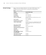
... Auto-sensing Switch 5500 Family Enabled Auto-negotiated Auto-negotiated Enabled on the Switch 5500G-EI (when a PoE PSU is returned to the untagged Default VLAN (VLAN 1) with IEEE Std 802.1Q-1998 learning operational. VLAN 1 IGMP filtering enabled Enabled Enabled Enabled Disabled per port Enabled Enabled 26 CHAPTER 1: INTRODUCING THE SUPERSTACK 4 SWITCH 5500 FAMILY Default...
... Auto-sensing Switch 5500 Family Enabled Auto-negotiated Auto-negotiated Enabled on the Switch 5500G-EI (when a PoE PSU is returned to the untagged Default VLAN (VLAN 1) with IEEE Std 802.1Q-1998 learning operational. VLAN 1 IGMP filtering enabled Enabled Enabled Enabled Disabled per port Enabled Enabled 26 CHAPTER 1: INTRODUCING THE SUPERSTACK 4 SWITCH 5500 FAMILY Default...

Getting Started Guide
Page 38
... it is connected. Connecting the Use the earthing cable that accompanies your Switch if the length is powered by the -48V DC power. The recommended cable length should not exceed 3 metres (9.84 feet). Alternatively use the earthing cable ... will be moved to the closed (on page 139. The earthing cable is only required if the Switch is Earthing Cable suitable. NULL 5500G PSU - 24 Port ~100-240V;50/60Hz;1.0A -48 -60V;2.0A NULL -48 -60V;2 0A Null Pinout - + Cable Tie When the RPS is connected to the Switch 3C17266 SuperStack 4 Switch + -
... it is connected. Connecting the Use the earthing cable that accompanies your Switch if the length is powered by the -48V DC power. The recommended cable length should not exceed 3 metres (9.84 feet). Alternatively use the earthing cable ... will be moved to the closed (on page 139. The earthing cable is only required if the Switch is Earthing Cable suitable. NULL 5500G PSU - 24 Port ~100-240V;50/60Hz;1.0A -48 -60V;2.0A NULL -48 -60V;2 0A Null Pinout - + Cable Tie When the RPS is connected to the Switch 3C17266 SuperStack 4 Switch + -

Getting Started Guide
Page 54
... refer to the Configuration Guide on the 3Com Web site. If the Switch is needed. You should use the automatic IP configuration method, you need to discover the automatically allocated IP information before you having to the "SuperStack 4 Switch 5500 Command Reference Guide" on the CD-ROM... that accompanies your chosen Management management method as described in "Methods of you can set up your Switch or the 3Com Web Site. For detailed information about the specific...
... refer to the Configuration Guide on the 3Com Web site. If the Switch is needed. You should use the automatic IP configuration method, you need to discover the automatically allocated IP information before you having to the "SuperStack 4 Switch 5500 Command Reference Guide" on the CD-ROM... that accompanies your chosen Management management method as described in "Methods of you can set up your Switch or the 3Com Web Site. For detailed information about the specific...

Getting Started Guide
Page 68
...as default. To change this setting in System View, enter display snmp community. The Switch has three default user names, and each user name has a different password and level of the "SuperStack 4 Switch Command Reference Guide" for the users defined on as possible, even if you need ...to the command line interface section of access. To manage your Switch. Table 18 Default Users User Name monitor manager admin Default ...
...as default. To change this setting in System View, enter display snmp community. The Switch has three default user names, and each user name has a different password and level of the "SuperStack 4 Switch Command Reference Guide" for the users defined on as possible, even if you need ...to the command line interface section of access. To manage your Switch. Table 18 Default Users User Name monitor manager admin Default ...

Getting Started Guide
Page 72
...-port gigabitethernet 1/0/51 enable, for XRN Distributed Fabric Switch Port used XRN support Switch 5500-SI 28-Port (3CR17151-91) Ports 27 (up port) and 28 (down Only supports DDM* port) using a 1000 Mbps SFP transceiver Switch 5500-SI 52-Port (3CR17152-91) Ports 51 (up port... one 'down') on the rear of the unit. * Distributed Device Management Stacking Switch 5500 Units 1 Ensure that the Switch units that you wish to operate in Fabric mode using the following CLI command. 72 CHAPTER 4: CREATING AN XRN STACKING FABRIC Table 19 SuperStack 4 Switch 5500 Support for example.
...-port gigabitethernet 1/0/51 enable, for XRN Distributed Fabric Switch Port used XRN support Switch 5500-SI 28-Port (3CR17151-91) Ports 27 (up port) and 28 (down Only supports DDM* port) using a 1000 Mbps SFP transceiver Switch 5500-SI 52-Port (3CR17152-91) Ports 51 (up port... one 'down') on the rear of the unit. * Distributed Device Management Stacking Switch 5500 Units 1 Ensure that the Switch units that you wish to operate in Fabric mode using the following CLI command. 72 CHAPTER 4: CREATING AN XRN STACKING FABRIC Table 19 SuperStack 4 Switch 5500 Support for example.

Getting Started Guide
Page 77
... Formation Problems If you may be included in the Support section of the SuperStack 4 Switch 5500 Family Command Reference Guide on the CD-ROM that accompanies your Switch. There is not listed here, it may have with the operation of your Switch. 5 PROBLEM SOLVING This chapter helps you to diagnose and solve problems you experience...
... Formation Problems If you may be included in the Support section of the SuperStack 4 Switch 5500 Family Command Reference Guide on the CD-ROM that accompanies your Switch. There is not listed here, it may have with the operation of your Switch. 5 PROBLEM SOLVING This chapter helps you to diagnose and solve problems you experience...

Getting Started Guide
Page 89
....aaa.aaa.aaa is the IP address of the TFTP server) s4a indicates the Switch filename, see Table 20 for further details: Table 20 Switch 5500 Family Filenames Filename Prefix s4a s4b s4c s4e Switch SuperStack 4 Switch 5500-SI software SuperStack 4 Switch 5500-EI software SuperStack 4 Switch 5500G-EI software SuperStack 4 Switch 5500 Family bootrom software 2 To download the Web user interface file, enter: tftp aaa...
....aaa.aaa.aaa is the IP address of the TFTP server) s4a indicates the Switch filename, see Table 20 for further details: Table 20 Switch 5500 Family Filenames Filename Prefix s4a s4b s4c s4e Switch SuperStack 4 Switch 5500-SI software SuperStack 4 Switch 5500-EI software SuperStack 4 Switch 5500G-EI software SuperStack 4 Switch 5500 Family bootrom software 2 To download the Web user interface file, enter: tftp aaa...

Getting Started Guide
Page 105
WARNING: You must ensure that the negative terminal on the Switch is connected to the positive (common) terminal of the RPS. AVERTISSEMENT: Si vous entassez l'unité Switch avec les unités SuperStack 4 Switch, l'unité Switch 5500 doit être installée en dessous des unités Hub plus étroites....une source de courant mise à la terre pour assurer la conformité aux normes de sécurité. WARNING: The Switch 5500 PWR and 5500G-EI supports Power over Ethernet on all front ports. These ports should only be used for Ethernet wiring within the same...
WARNING: You must ensure that the negative terminal on the Switch is connected to the positive (common) terminal of the RPS. AVERTISSEMENT: Si vous entassez l'unité Switch avec les unités SuperStack 4 Switch, l'unité Switch 5500 doit être installée en dessous des unités Hub plus étroites....une source de courant mise à la terre pour assurer la conformité aux normes de sécurité. WARNING: The Switch 5500 PWR and 5500G-EI supports Power over Ethernet on all front ports. These ports should only be used for Ethernet wiring within the same...


