
Getting Started Guide
Page 3
... 10BASE-T/ 100BASE-TX/ 1000BASE-T Ports 18 1000BASE-X SFP Ports 19 100BASE-X SFP Ports (Switch 5500-EI FX only) 19 Console Port 19 Unit LED 20 LEDs 20 Switch 5500 Family - Rear View Detail 23 Switch 5500 23 Switch 5500G-EI 24 Expansion Module Slot 24 Power Socket 24 Open Book Warning Labels 24 Redundant... Power System Socket 25 Stacking Cable Ports (Switch 5500G-EI) 25 CONTENTS ABOUT THIS GUIDE Before You...
... 10BASE-T/ 100BASE-TX/ 1000BASE-T Ports 18 1000BASE-X SFP Ports 19 100BASE-X SFP Ports (Switch 5500-EI FX only) 19 Console Port 19 Unit LED 20 LEDs 20 Switch 5500 Family - Rear View Detail 23 Switch 5500 23 Switch 5500G-EI 24 Expansion Module Slot 24 Power Socket 24 Open Book Warning Labels 24 Redundant... Power System Socket 25 Stacking Cable Ports (Switch 5500G-EI) 25 CONTENTS ABOUT THIS GUIDE Before You...

Getting Started Guide
Page 4
... Contents 28 Choosing a Suitable Site 29 Rack-mounting 30 Switch 5500 (non PoE) 30 Switch 5500 and Switch 5500G-EI (PoE) 32 Connecting a Redundant Power Supply 33 Specifying the Redundant Power System 36 Connecting the Switch to the Redundant Power System 37 Connecting the Earthing Cable 38 RPS LED 39 Using Power over ...Ethernet 39 Placing Units On Top of Each Other 40 The Power-up Sequence 40 Powering-up the Switch 5500 40 Checking for Correct Operation of LEDs 40 Choosing the Correct Cables 41 Choosing the Correct Cables for the 1000BASE-X SFP Ports 42 Choosing...
... Contents 28 Choosing a Suitable Site 29 Rack-mounting 30 Switch 5500 (non PoE) 30 Switch 5500 and Switch 5500G-EI (PoE) 32 Connecting a Redundant Power Supply 33 Specifying the Redundant Power System 36 Connecting the Switch to the Redundant Power System 37 Connecting the Earthing Cable 38 RPS LED 39 Using Power over ...Ethernet 39 Placing Units On Top of Each Other 40 The Power-up Sequence 40 Powering-up the Switch 5500 40 Checking for Correct Operation of LEDs 40 Choosing the Correct Cables 41 Choosing the Correct Cables for the 1000BASE-X SFP Ports 42 Choosing...

Getting Started Guide
Page 6
... Cable 124 Ethernet Port RJ-45 Pin Assignments 124 C TECHNICAL SPECIFICATIONS Switch 5500 (28 Port) 128 Switch 5500 PWR (28 Port) 129 Switch 5500 (52 Port) 130 Switch 5500 PWR (52 Port) 131 Switch 5500 FX (28 Port) 132 Switch 5500G-EI (24 Port) 133 Switch 5500G-EI PWR (24 Port) 134 Switch 5500G-EI (48 Port) 135 FTP (via a network port) 91...
... Cable 124 Ethernet Port RJ-45 Pin Assignments 124 C TECHNICAL SPECIFICATIONS Switch 5500 (28 Port) 128 Switch 5500 PWR (28 Port) 129 Switch 5500 (52 Port) 130 Switch 5500 PWR (52 Port) 131 Switch 5500 FX (28 Port) 132 Switch 5500G-EI (24 Port) 133 Switch 5500G-EI PWR (24 Port) 134 Switch 5500G-EI (48 Port) 135 FTP (via a network port) 91...

Getting Started Guide
Page 7
Switch 5500G-EI PWR (48 Port) 136 Switch 5500G-EI SFP (24-Port) 137 RPS 138 Earthing Lead 139 D OBTAINING SUPPORT FOR YOUR PRODUCT Register Your Product 141 Purchase Value-Added Services 141 Troubleshoot Online 142 Access Software Downloads 142 Telephone Technical Support and Repair 142 Contact Us 143 INDEX REGULATORY NOTICES
Switch 5500G-EI PWR (48 Port) 136 Switch 5500G-EI SFP (24-Port) 137 RPS 138 Earthing Lead 139 D OBTAINING SUPPORT FOR YOUR PRODUCT Register Your Product 141 Purchase Value-Added Services 141 Troubleshoot Online 142 Access Software Downloads 142 Telephone Technical Support and Repair 142 Contact Us 143 INDEX REGULATORY NOTICES

Getting Started Guide
Page 9
...■ A number of LANs (Local Area Networks). The guide is intended for details. ■ 3Com Network Director - Before You Start This section contains information about the Switch 5500 - consequently, it assumes a basic working knowledge of other useful applications. ABOUT THIS GUIDE This guide provides... all the information you need to install and use 3Com® SuperStack® 4 Switch 5500 in the release notes. If the information in the release notes differ from the information in this guide, follow...
...■ A number of LANs (Local Area Networks). The guide is intended for details. ■ 3Com Network Director - Before You Start This section contains information about the Switch 5500 - consequently, it assumes a basic working knowledge of other useful applications. ABOUT THIS GUIDE This guide provides... all the information you need to install and use 3Com® SuperStack® 4 Switch 5500 in the release notes. If the information in the release notes differ from the information in this guide, follow...

Getting Started Guide
Page 11
... displayed automatically. 2 Select the Documentation section from the contents page. If your Switch, Documentation do the following : ■ SuperStack 4 Switch 5500 Quick Reference Guide for the Switch. This guide is also supplied under the Help button on the web interface. ■ SuperStack 4 Switch 5500 Configuration Guide This guide contains information on the CD-ROM that accompanies...
... displayed automatically. 2 Select the Documentation section from the contents page. If your Switch, Documentation do the following : ■ SuperStack 4 Switch 5500 Quick Reference Guide for the Switch. This guide is also supplied under the Help button on the web interface. ■ SuperStack 4 Switch 5500 Configuration Guide This guide contains information on the CD-ROM that accompanies...

Getting Started Guide
Page 12
... Page number (if appropriate). They will help make our documentation more useful to us. Example: Part Number DUA1725-0AAA01 3Com SuperStack 4 Switch 5500 Getting Started Guide Page 21 Please note that we can only respond to comments and questions about this e-mail address. ...The PDF Configuration Guide is stored in the first instance to your network supplier. Please e-mail comments about 3Com product documentation at this document to 3Com at: pddtechpubs_comments@3com.com Please include the following information when commenting: Document title, Document part number (on the CD-ROM...
... Page number (if appropriate). They will help make our documentation more useful to us. Example: Part Number DUA1725-0AAA01 3Com SuperStack 4 Switch 5500 Getting Started Guide Page 21 Please note that we can only respond to comments and questions about this e-mail address. ...The PDF Configuration Guide is stored in the first instance to your network supplier. Please e-mail comments about 3Com product documentation at this document to 3Com at: pddtechpubs_comments@3com.com Please include the following information when commenting: Document title, Document part number (on the CD-ROM...

Getting Started Guide
Page 13
Front View Detail ■ Switch 5500 Family - It covers summary information about the Switch 5500 Family and how they can be used in your network. Rear View Detail ■ Default Settings 1 INTRODUCING THE SUPERSTACK 4 SWITCH 5500 FAMILY This chapter contains introductory information about the hardware and the following topics: ■ About the Switch 5500 Family ■ Switch 5500 Family -
Front View Detail ■ Switch 5500 Family - It covers summary information about the Switch 5500 Family and how they can be used in your network. Rear View Detail ■ Default Settings 1 INTRODUCING THE SUPERSTACK 4 SWITCH 5500 FAMILY This chapter contains introductory information about the hardware and the following topics: ■ About the Switch 5500 Family ■ Switch 5500 Family -

Getting Started Guide
Page 14
...-45 Console Port -48V DC RPS Input Module Slot Switch 5500 Family Switch 5500-SI 28 Port 24 4 11 Switch 5500-SI 52 Port 48 4 11 Switch 5500-EI 28 Port 24 4 11 Switch 5500-EI 52 Port 48 4 11 Switch 5500 PWR 28 Port 24 4 11 Switch 5500 PWR 52 Port 48 4 11 Switch 5500 FX 28 Port 2 24 2 11 Switch 5500G-EI 24 Port 24 24* 4†...
...-45 Console Port -48V DC RPS Input Module Slot Switch 5500 Family Switch 5500-SI 28 Port 24 4 11 Switch 5500-SI 52 Port 48 4 11 Switch 5500-EI 28 Port 24 4 11 Switch 5500-EI 52 Port 48 4 11 Switch 5500 PWR 28 Port 24 4 11 Switch 5500 PWR 52 Port 48 4 11 Switch 5500 FX 28 Port 2 24 2 11 Switch 5500G-EI 24 Port 24 24* 4†...

Getting Started Guide
Page 15
...Std 802.1D, 1998 Edition) Eight traffic queues per port Power over Ethernet Supported on front panel ports, except SFP ports. (Switch 5500) (3CR17171 and 3CR17172 only) Power over Ethernet Supported on all ports. Fast Ethernet and Auto-negotiating 10BASE-T/100BASE-TX/1000BASE-T Gigabit...In full duplex operation, all ports are supported. If fiber SFP transceivers are supported by the Hardware Features Switch 5500 Family. Ethernet and Fast Ethernet Ports (Switch 5500) Auto-negotiating 10BASE-T/100BASE-TX ports or 100BASE-X ports. Duplex Modes Half and Full duplex on all front...
...Std 802.1D, 1998 Edition) Eight traffic queues per port Power over Ethernet Supported on front panel ports, except SFP ports. (Switch 5500) (3CR17171 and 3CR17172 only) Power over Ethernet Supported on all ports. Fast Ethernet and Auto-negotiating 10BASE-T/100BASE-TX/1000BASE-T Gigabit...In full duplex operation, all ports are supported. If fiber SFP transceivers are supported by the Hardware Features Switch 5500 Family. Ethernet and Fast Ethernet Ports (Switch 5500) Auto-negotiating 10BASE-T/100BASE-TX ports or 100BASE-X ports. Duplex Modes Half and Full duplex on all front...

Getting Started Guide
Page 16
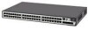
... RPS LED 10/100BASE-TX Ports 1000BASE-X Ports Unit LED Mode LED Power LED Figure 2 Switch 5500 SI and EI 52-Port - front view PWR LED 1000BASE-X Ports Port Status LEDs Console Port RPS LED 3CR17171-91 SuperStack 4 Switch 5500 PWR 28 Port Green=Status Yellow=Packet Red=PoE 10/100BASE-TX Ports 1000BASE-X Ports...
... RPS LED 10/100BASE-TX Ports 1000BASE-X Ports Unit LED Mode LED Power LED Figure 2 Switch 5500 SI and EI 52-Port - front view PWR LED 1000BASE-X Ports Port Status LEDs Console Port RPS LED 3CR17171-91 SuperStack 4 Switch 5500 PWR 28 Port Green=Status Yellow=Packet Red=PoE 10/100BASE-TX Ports 1000BASE-X Ports...

Getting Started Guide
Page 17
... Ports Unit LED 10/100/1000BASE-T Ports Power LED Mode LED Switch 5500G-EI Figure 6 Switch 5500G-EI (24 port) - Switch 5500 Family - Front View Detail 17 Figure 4 Switch 5500-EI 52-Port PWR - front view Port Status LEDs Status:Green... 20 9 21 10 22 11 23 12 24 21 22 23 Unit LED PWR LED RPS LED 3CR17251-91 SuperStack 4 Switch 5500G-EI 24-Port PWR Mode: 24 Console Unit 100% Green=Status 80% Yellow=Packet 60% Red=POE RPS MOD 40...Port Unit LED RPS LED Mode LED 3CR17172-91 SuperStack 4 Switch 5500 PWR 52 Port Green=Status Yellow=Packet Red=PoE 10/100BASE-TX Ports Figure...
... Ports Unit LED 10/100/1000BASE-T Ports Power LED Mode LED Switch 5500G-EI Figure 6 Switch 5500G-EI (24 port) - Switch 5500 Family - Front View Detail 17 Figure 4 Switch 5500-EI 52-Port PWR - front view Port Status LEDs Status:Green... 20 9 21 10 22 11 23 12 24 21 22 23 Unit LED PWR LED RPS LED 3CR17251-91 SuperStack 4 Switch 5500G-EI 24-Port PWR Mode: 24 Console Unit 100% Green=Status 80% Yellow=Packet 60% Red=POE RPS MOD 40...Port Unit LED RPS LED Mode LED 3CR17172-91 SuperStack 4 Switch 5500 PWR 52 Port Green=Status Yellow=Packet Red=PoE 10/100BASE-TX Ports Figure...

Getting Started Guide
Page 18
...MOD STK Stack LED 10/100/1000BASE-T Ports Dual Personality Module LED 10/100/1000BASE-T/ 1000BASE-X SFP Ports Figure 8 Switch 5500G-EI SFP (24 port) - These are configured as standard traditional telephone sockets, or to connect the unit to...):Green=Full Duplex Yellow=Half Duplex 1000Base-X 1000Base-X Power LED RPS LED 25/11 SD 3CR17259-91 SuperStack 4 Switch 5500G-EI SFP 24-Port 26/12 SD 27/23 SD 28/24 SD 10/100/1000Base-TX PWR RPS ... Stack LED LED WARNING: RJ-45 Ports. 18 CHAPTER 1: INTRODUCING THE SUPERSTACK 4 SWITCH 5500 FAMILY Figure 7 Switch 5500G-EI (48 port) -
...MOD STK Stack LED 10/100/1000BASE-T Ports Dual Personality Module LED 10/100/1000BASE-T/ 1000BASE-X SFP Ports Figure 8 Switch 5500G-EI SFP (24 port) - These are configured as standard traditional telephone sockets, or to connect the unit to...):Green=Full Duplex Yellow=Half Duplex 1000Base-X 1000Base-X Power LED RPS LED 25/11 SD 3CR17259-91 SuperStack 4 Switch 5500G-EI SFP 24-Port 26/12 SD 27/23 SD 28/24 SD 10/100/1000Base-TX PWR RPS ... Stack LED LED WARNING: RJ-45 Ports. 18 CHAPTER 1: INTRODUCING THE SUPERSTACK 4 SWITCH 5500 FAMILY Figure 7 Switch 5500G-EI (48 port) -

Getting Started Guide
Page 19
...by the media type, only the flow control is auto-negotiation enabled, where the speed, duplex and flow control modes are 100Mbps (Switch 5500-EI FX ports that can be disabled (except 1000BASE-T where auto-negotiation is 19,200. Console Port The console port allows you .... The default baud rate is mandatory) and the flow control setting can be manually configured. 100BASE-X SFP Ports The Switch 5500-EI FX has 24 100BASE-X SFP ports. Switch 5500 Family - Alternatively, auto-negotiation can be manually configured. Duplex and flow control must be disabled. Front View Detail 19...
...by the media type, only the flow control is auto-negotiation enabled, where the speed, duplex and flow control modes are 100Mbps (Switch 5500-EI FX ports that can be disabled (except 1000BASE-T where auto-negotiation is 19,200. Console Port The console port allows you .... The default baud rate is mandatory) and the flow control setting can be manually configured. 100BASE-X SFP Ports The Switch 5500-EI FX has 24 100BASE-X SFP ports. Switch 5500 Family - Alternatively, auto-negotiation can be manually configured. Duplex and flow control must be disabled. Front View Detail 19...

Getting Started Guide
Page 20
...for problem solving, see "Checking for every packet received or transmitted. Yellow PoE error, no power supplied on the front of the Switch, and how to read their status according to diagnose hardware faults, display POST test ID, display Stack ID, display PoE utilization and ...software upgrade information. Off No link is present. Yellow flashing The port has failed post. 20 CHAPTER 1: INTRODUCING THE SUPERSTACK 4 SWITCH 5500 FAMILY Unit LED The Unit LED is present. For information on using the LEDs for problem solving, see "Solving Problems Indicated by LEDs"...
...for problem solving, see "Checking for every packet received or transmitted. Yellow PoE error, no power supplied on the front of the Switch, and how to read their status according to diagnose hardware faults, display POST test ID, display Stack ID, display PoE utilization and ...software upgrade information. Off No link is present. Yellow flashing The port has failed post. 20 CHAPTER 1: INTRODUCING THE SUPERSTACK 4 SWITCH 5500 FAMILY Unit LED The Unit LED is present. For information on using the LEDs for problem solving, see "Solving Problems Indicated by LEDs"...

Getting Started Guide
Page 21
... LED Color Indicates Duplex Green Full duplex, blinking off for every packet received or transmitted. Off No link is present. Yellow flashing Port failed POST. Switch 5500 Family - Yellow flashing The port has failed post. Duplex Green Full duplex packets are being transmitted/received on the port. Yellow Half duplex, blinking off...
... LED Color Indicates Duplex Green Full duplex, blinking off for every packet received or transmitted. Off No link is present. Yellow flashing Port failed POST. Switch 5500 Family - Yellow flashing The port has failed post. Duplex Green Full duplex packets are being transmitted/received on the port. Yellow Half duplex, blinking off...

Getting Started Guide
Page 22
...not supported or faulty. Yellow flashing The Module is critical. RPS supply is functioning without the loop connection. Green flashing The Switch has failed POST. Off Stacking Cables are not connected. Yellow The XRN stack is OK. Mode LED Duplex Yellow 10/...not installed. Off There is not compatible with the other Switches in the stack. Green flashing 'f' There has been a fan failure. Green flashing Switch is no RPS supply connected. 22 CHAPTER 1: INTRODUCING THE SUPERSTACK 4 SWITCH 5500 FAMILY LED Color Indicates Unit LED Green Power on Self Test...
...not supported or faulty. Yellow flashing The Module is critical. RPS supply is functioning without the loop connection. Green flashing The Switch has failed POST. Off Stacking Cables are not connected. Yellow The XRN stack is OK. Mode LED Duplex Yellow 10/...not installed. Off There is not compatible with the other Switches in the stack. Green flashing 'f' There has been a fan failure. Green flashing Switch is no RPS supply connected. 22 CHAPTER 1: INTRODUCING THE SUPERSTACK 4 SWITCH 5500 FAMILY LED Color Indicates Unit LED Green Power on Self Test...

Getting Started Guide
Page 23
... View Detail 23 LED Color PWR LED Green Green flashing Yellow flashing Red Off Indicates The Switch is a fault with the Power Supply Unit. The Switch has failed its Power On Self Test. Switch 5500 Family - rear view Power Socket Open Book Warning Labels NULL 100-240V; 50/60Hz;...50/60Hz; 7.0A -52 -55V;19.5A Redundant Power System Socket Open Book Warning Labels Earthing Screw Earthing Screw Switch 5500 Family - Rear View Detail Switch 5500 Figure 9 Switch 5500 SI, EI and FX - Self Test (POST) or Software Download is in progress. One or more ports have failed POST.
... View Detail 23 LED Color PWR LED Green Green flashing Yellow flashing Red Off Indicates The Switch is a fault with the Power Supply Unit. The Switch has failed its Power On Self Test. Switch 5500 Family - rear view Power Socket Open Book Warning Labels NULL 100-240V; 50/60Hz;...50/60Hz; 7.0A -52 -55V;19.5A Redundant Power System Socket Open Book Warning Labels Earthing Screw Earthing Screw Switch 5500 Family - Rear View Detail Switch 5500 Figure 9 Switch 5500 SI, EI and FX - Self Test (POST) or Software Download is in progress. One or more ports have failed POST.

Getting Started Guide
Page 24
...Fault Stacking Cable Port (Up) Stacking Cable Port (Down) Expansion Module You can use this guide. VORSICHT:Bevor Sie Komponenten der Switch 5500-Baureihe installieren oder deinstallieren und bevor Sie Wartungsarbeiten ausführen, müssen Sie die in Appendix A of this slot to...void the product warranty. Failure to install an Expansion Module. AVERTISSEMENT: Avant d'installer ou d'enlever tout composant des commutateurs de la gamme Switch 5500 ou d'entamer une procédure de maintenance, lisez les informations relatives à la sécurité qui se trouvent dans ...
...Fault Stacking Cable Port (Up) Stacking Cable Port (Down) Expansion Module You can use this guide. VORSICHT:Bevor Sie Komponenten der Switch 5500-Baureihe installieren oder deinstallieren und bevor Sie Wartungsarbeiten ausführen, müssen Sie die in Appendix A of this slot to...void the product warranty. Failure to install an Expansion Module. AVERTISSEMENT: Avant d'installer ou d'enlever tout composant des commutateurs de la gamme Switch 5500 ou d'entamer une procédure de maintenance, lisez les informations relatives à la sécurité qui se trouvent dans ...

Getting Started Guide
Page 25
...) - Redundant Power To protect against internal power supply failure, you to stack together two switches up to create a Fabric by interconnecting a 3Com Switch 5500 with Standard Image (SI) units. Rear View Detail 25 AVVERTENZA: Prima di installare o rimuovere qualsiasi componente dello Switch 5500 Family o di eseguire qualsiasi procedura di manutenzione, leggere le informazioni di sicurezza riportate nell...
...) - Redundant Power To protect against internal power supply failure, you to stack together two switches up to create a Fabric by interconnecting a 3Com Switch 5500 with Standard Image (SI) units. Rear View Detail 25 AVVERTENZA: Prima di installare o rimuovere qualsiasi componente dello Switch 5500 Family o di eseguire qualsiasi procedura di manutenzione, leggere le informazioni di sicurezza riportate nell...


