
Installation Guide
Page 1
Switch 7700 Installation Guide Version 3.0 3C16850 7-slot Starter Kit 3C16852 8-slot Starter Kit 3C16870 4-slot Starter Kit and associated modules http://www.3com.com/ Part No. 10014180 Document Number: DUA1685-0AA02 Published November 2004
Switch 7700 Installation Guide Version 3.0 3C16850 7-slot Starter Kit 3C16852 8-slot Starter Kit 3C16870 4-slot Starter Kit and associated modules http://www.3com.com/ Part No. 10014180 Document Number: DUA1685-0AA02 Published November 2004

Installation Guide
Page 3
CONTENTS ABOUT THIS GUIDE Conventions 7 Related Documentation 8 SWITCH 7700 COMPONENTS Switch Chassis 9 Switch Backplane 9 Fabric Module 10 Submodule Slot 11 Reset Button 11 Fixed Ports 11 Module LEDs 12 Power LEDs 13 Fan LED 13 Fabric 32 Submodules ... 19 20-Port 10/100/1000BASE-T Module 20 20-Port 1000BASE-X-SFP Module 22 1-Port 10GBASE-R-XENPAK Module 23 Power Module 24 Fan Assembly 25 Switch 7700 Specifications 26 Switch 7700 Software Features 27 INSTALLING THE SWITCH 7700 Preparing to Install 29 General Safety Recommendations 29 Electrical Safety 30 Moving the...
CONTENTS ABOUT THIS GUIDE Conventions 7 Related Documentation 8 SWITCH 7700 COMPONENTS Switch Chassis 9 Switch Backplane 9 Fabric Module 10 Submodule Slot 11 Reset Button 11 Fixed Ports 11 Module LEDs 12 Power LEDs 13 Fan LED 13 Fabric 32 Submodules ... 19 20-Port 10/100/1000BASE-T Module 20 20-Port 1000BASE-X-SFP Module 22 1-Port 10GBASE-R-XENPAK Module 23 Power Module 24 Fan Assembly 25 Switch 7700 Specifications 26 Switch 7700 Software Features 27 INSTALLING THE SWITCH 7700 Preparing to Install 29 General Safety Recommendations 29 Electrical Safety 30 Moving the...

Installation Guide
Page 4
... the AUX Cable 36 Connecting Module Cables 37 Installing Cabling 38 Bench-Mounted Switch 38 Rack-Mounted Switch 38 Cable Binding 38 Post-installation Checklist 39 CONFIGURING THE SWITCH 7700 Configuring the Switch 7700 and a Local Terminal 41 Setting Terminal Parameters 41 Booting the Switch 7700 44 Powering up and Booting 45 MAINTAINING SOFTWARE Upgrading Software 47 Upgrading...
... the AUX Cable 36 Connecting Module Cables 37 Installing Cabling 38 Bench-Mounted Switch 38 Rack-Mounted Switch 38 Cable Binding 38 Post-installation Checklist 39 CONFIGURING THE SWITCH 7700 Configuring the Switch 7700 and a Local Terminal 41 Setting Terminal Parameters 41 Booting the Switch 7700 44 Powering up and Booting 45 MAINTAINING SOFTWARE Upgrading Software 47 Upgrading...

Installation Guide
Page 5
... No information is displayed on the terminal 61 The displayed characters are illegible 61 Troubleshooting Power 61 Troubleshooting the Fan 62 Troubleshooting the Modules 62 SWITCH 7700 CABLES Console Cable 63 AUX Cable 63 Electrical Port Connector 64 Optical Fiber Cable Connectors 65 OBTAINING SUPPORT FOR YOUR...
... No information is displayed on the terminal 61 The displayed characters are illegible 61 Troubleshooting Power 61 Troubleshooting the Fan 62 Troubleshooting the Modules 62 SWITCH 7700 CABLES Console Cable 63 AUX Cable 63 Electrical Port Connector 64 Optical Fiber Cable Connectors 65 OBTAINING SUPPORT FOR YOUR...

Installation Guide
Page 7
... communication protocols that describes important features or instructions. ABOUT THIS GUIDE Conventions This guide describes the 3Com® Switch 7700 and how to interconnect LANs. This guide also provides troubleshooting and support information for configuring, using, and managing the... switches. Always download the Release Notes for your switch. Information that alerts you to an application, system, or device. It assumes a working ...
... communication protocols that describes important features or instructions. ABOUT THIS GUIDE Conventions This guide describes the 3Com® Switch 7700 and how to interconnect LANs. This guide also provides troubleshooting and support information for configuring, using, and managing the... switches. Always download the Release Notes for your switch. Information that alerts you to an application, system, or device. It assumes a working ...

Installation Guide
Page 8
... Contains the latest information about your router or on the CD-ROM that you require to manage your Switch 7700: ■ Switch 7700 Command Reference Guide - These documents are used to : Emphasize a point. Describes how to ..." 8... ABOUT THIS GUIDE Related Documentation Table 2 Text Conventions Convention Words in italics Words in bold Description Italics are available in Adobe Acrobat Reader Portable Document Format (PDF) on the 3Com World Wide Web site: http://www.3com...
... Contains the latest information about your router or on the CD-ROM that you require to manage your Switch 7700: ■ Switch 7700 Command Reference Guide - These documents are used to : Emphasize a point. Describes how to ..." 8... ABOUT THIS GUIDE Related Documentation Table 2 Text Conventions Convention Words in italics Words in bold Description Italics are available in Adobe Acrobat Reader Portable Document Format (PDF) on the 3Com World Wide Web site: http://www.3com...

Installation Guide
Page 9
... ■ Power Module ■ Fan Assembly ■ Switch 7700 Specifications ■ Switch 7700 Software Features There are three Switch 7700 Models, the 4-Slot, 7-Slot, and the 8-Slot. The backplane supports the following Switch 7700 components: ■ Switch Chassis ■ Switch Backplane ■ Fabric Module ■ Fabric 32 Submodules ■ I /O modules. 1 SWITCH 7700 COMPONENTS Switch Chassis Switch Backplane The chapter describes the following functions: ■...
... ■ Power Module ■ Fan Assembly ■ Switch 7700 Specifications ■ Switch 7700 Software Features There are three Switch 7700 Models, the 4-Slot, 7-Slot, and the 8-Slot. The backplane supports the following Switch 7700 components: ■ Switch Chassis ■ Switch Backplane ■ Fabric Module ■ Fabric 32 Submodules ■ I /O modules. 1 SWITCH 7700 COMPONENTS Switch Chassis Switch Backplane The chapter describes the following functions: ■...

Installation Guide
Page 10
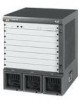
... Fabric Module There are two Fabric modules for the Switch 7700: ■ Fabric 64 (3C16857 or 3C16857R) ■ Fabric 32 (3C16872)...I /O modules through the backplane and forwards Layer 2 and Layer 3 data ■ Manages and calculates routing ■ Performs the switch's software upgrade and system reset functions ■ Monitors system power and the fan frame Figure 1 illustrates the front panel of the ... 5 Fan LEDs 6 Power module LEDs 7 I/O module LEDs 56 7 Figure 2 illustrates the front panel of Switch 7700 system. You can install the Fabric 64 only in a 4-slot chassis.
... Fabric Module There are two Fabric modules for the Switch 7700: ■ Fabric 64 (3C16857 or 3C16857R) ■ Fabric 32 (3C16872)...I /O modules through the backplane and forwards Layer 2 and Layer 3 data ■ Manages and calculates routing ■ Performs the switch's software upgrade and system reset functions ■ Monitors system power and the fan frame Figure 1 illustrates the front panel of the ... 5 Fan LEDs 6 Power module LEDs 7 I/O module LEDs 56 7 Figure 2 illustrates the front panel of Switch 7700 system. You can install the Fabric 64 only in a 4-slot chassis.

Installation Guide
Page 11
... 5 Console Port Specifications Specification Port connector Port standard Description RJ-45 Asynchronous EIA/TIA-232 Fixed Ports The Switch 7700 Fabric module provides the following submodules: ■ 4-port 1000BASE-X-GBIC submodule ■ 4-port 10/100/1000BASE-T submodule For more information on these submodules, see "Fabric ...
... 5 Console Port Specifications Specification Port connector Port standard Description RJ-45 Asynchronous EIA/TIA-232 Fixed Ports The Switch 7700 Fabric module provides the following submodules: ■ 4-port 1000BASE-X-GBIC submodule ■ 4-port 10/100/1000BASE-T submodule For more information on these submodules, see "Fabric ...

Installation Guide
Page 12
...1 10 Mbps, half/full duplex 100 Mbps, half/full duplex MDIX Category-5 twisted pair for transmission within 100 m (300 ft) Switch software upgrade and network management See "Electrical Port Connector" on the Fabric is working normally. Green flashing - You can also be connected... LEDs The module LEDs show the status of the I /O Module LEDs LED RUN ALM Status description Green or off - 12 CHAPTER 1: SWITCH 7700 COMPONENTS Table 5 Console Port Specifications (continued) Specification Baud rate Transmission distance Services Description 9600 bps (by default) 15 m (45 ft) Connects...
...1 10 Mbps, half/full duplex 100 Mbps, half/full duplex MDIX Category-5 twisted pair for transmission within 100 m (300 ft) Switch software upgrade and network management See "Electrical Port Connector" on the Fabric is working normally. Green flashing - You can also be connected... LEDs The module LEDs show the status of the I /O Module LEDs LED RUN ALM Status description Green or off - 12 CHAPTER 1: SWITCH 7700 COMPONENTS Table 5 Console Port Specifications (continued) Specification Baud rate Transmission distance Services Description 9600 bps (by default) 15 m (45 ft) Connects...

Installation Guide
Page 14
... µm multi-mode fiber 62.5/125 µm Multi-mode fiber SC 9/125 µm Single-mode fiber SC 9/125 µm Single-mode fiber Max. 14 CHAPTER 1: SWITCH 7700 COMPONENTS Table 12 lists the specifications for each of the 4-port 1000BASE-X-GBIC submodule. Figure 4 illustrates the 4-port 10/100/1000BASE-T submodule. No data is...
... µm multi-mode fiber 62.5/125 µm Multi-mode fiber SC 9/125 µm Single-mode fiber SC 9/125 µm Single-mode fiber Max. 14 CHAPTER 1: SWITCH 7700 COMPONENTS Table 12 lists the specifications for each of the 4-port 1000BASE-X-GBIC submodule. Figure 4 illustrates the 4-port 10/100/1000BASE-T submodule. No data is...

Installation Guide
Page 15
... module provides 48 external Auto-sensing FE Module 100Mbps Ethernet electrical ports. Figure 5 illustrates the 48-port 10/100BASE-T Auto-sensing FE module. I/O Modules The Switch 7700 provides slots for an illustration of the 48-Port 10/100BASE-T Auto-sensing FE module 12 Figure 6 Front Panel of the RJ-45 connector and...
... module provides 48 external Auto-sensing FE Module 100Mbps Ethernet electrical ports. Figure 5 illustrates the 48-port 10/100BASE-T Auto-sensing FE module. I/O Modules The Switch 7700 provides slots for an illustration of the 48-Port 10/100BASE-T Auto-sensing FE module 12 Figure 6 Front Panel of the RJ-45 connector and...

Installation Guide
Page 16
... LED LED LINK/ACT Description Green - A GBIC module is not connected Green flashing - The port is used for each data receiving/transmitting channel. 16 CHAPTER 1: SWITCH 7700 COMPONENTS 1 Ethernet port 2 Ethernet port LED Each 100 Mbps Ethernet port has a green LED, indicating LINK/ACTIVE status. IEEE802.3 IEEE802.3u IEEE802.3x See "Electrical...
... LED LED LINK/ACT Description Green - A GBIC module is not connected Green flashing - The port is used for each data receiving/transmitting channel. 16 CHAPTER 1: SWITCH 7700 COMPONENTS 1 Ethernet port 2 Ethernet port LED Each 100 Mbps Ethernet port has a green LED, indicating LINK/ACTIVE status. IEEE802.3 IEEE802.3u IEEE802.3x See "Electrical...

Installation Guide
Page 18
18 CHAPTER 1: SWITCH 7700 COMPONENTS Table 19 Specifications for the 8-Port 1000BASE-X GE Module (continued) Specification BootROM SDRAM Dimensions (L x W) Maximum power consumption Number of the 8-Port 10/100/1000BASE-T ...
18 CHAPTER 1: SWITCH 7700 COMPONENTS Table 19 Specifications for the 8-Port 1000BASE-X GE Module (continued) Specification BootROM SDRAM Dimensions (L x W) Maximum power consumption Number of the 8-Port 10/100/1000BASE-T ...

Installation Guide
Page 20
... LED LINK/ACT Description Green - Table 23 describes the specifications of 1300 nm. Figure 13 illustrates the 20-Port 10/100/1000BASE-T Module. 20 CHAPTER 1: SWITCH 7700 COMPONENTS Each 100 Mbps optical port has a green LED, as shown in ) 55 W MT-RJ 24 100 Mbps, full-duplex 62.5/125 µm multi-mode...
... LED LINK/ACT Description Green - Table 23 describes the specifications of 1300 nm. Figure 13 illustrates the 20-Port 10/100/1000BASE-T Module. 20 CHAPTER 1: SWITCH 7700 COMPONENTS Each 100 Mbps optical port has a green LED, as shown in ) 55 W MT-RJ 24 100 Mbps, full-duplex 62.5/125 µm multi-mode...

Installation Guide
Page 22
22 CHAPTER 1: SWITCH 7700 COMPONENTS Table 25 Specifications for the 20-Port 10/100/1000BASE-T Module (continued) Specification Cable and maximum transmission distance Compliance Description Category-5 twisted pair 100 m (...
22 CHAPTER 1: SWITCH 7700 COMPONENTS Table 25 Specifications for the 20-Port 10/100/1000BASE-T Module (continued) Specification Cable and maximum transmission distance Compliance Description Category-5 twisted pair 100 m (...

Installation Guide
Page 24
... Off - The port is required for the 4-slot chassis. Table 31 describes the specifications of these fully loaded Switch 7700 systems. Table 28 1-Port 10GBASE-R-XENPAK Module LEDs LED Description LINK On - 24 CHAPTER 1: SWITCH 7700 COMPONENTS Power Module Table 28 describes the 1-port 10GBASE-R-XENPAK module LEDs. Table 29 Specifications for the 1-Port...
... Off - The port is required for the 4-slot chassis. Table 31 describes the specifications of these fully loaded Switch 7700 systems. Table 28 1-Port 10GBASE-R-XENPAK Module LEDs LED Description LINK On - 24 CHAPTER 1: SWITCH 7700 COMPONENTS Power Module Table 28 describes the 1-port 10GBASE-R-XENPAK module LEDs. Table 29 Specifications for the 1-Port...

Installation Guide
Page 25
...; 7-slot chassis - 3C16856 ■ 8-slot chassis - 3C16855 The fans are collected and transmitted to -60 V 460 W 2 lightening protectors in the DC power distributing box The Switch 7700 power distribution box is available in the back of power module. Fan Assembly Fan Assembly 25 The 7- Table 31 describes the specifications of each type...
...; 7-slot chassis - 3C16856 ■ 8-slot chassis - 3C16855 The fans are collected and transmitted to -60 V 460 W 2 lightening protectors in the DC power distributing box The Switch 7700 power distribution box is available in the back of power module. Fan Assembly Fan Assembly 25 The 7- Table 31 describes the specifications of each type...

Installation Guide
Page 26
26 CHAPTER 1: SWITCH 7700 COMPONENTS Figure 19 Fan Assembly Switch 7700 Specifications Table 32 provides detailed information about features of the Switch 7700. Table 32 Specifications for the Switch 7700 System Item 4-Slot Chassis 7-Slot Chassis 8-Slot Chassis Dimensions (W x H x D) 436 x 352.8 x 480 mm 436 x 486.2 x 480 mm 436 x 530.6 ... 24-port 100BASE-FX MMF FE Module 20-Port 10/100/1000BASE-T Module 20-Port 1000BASE-X-SFP Module 1-port 10GBASE-R-XENPAK Module System switching 32 Gbps 64 Gbps Packet processing 24 Mpps 48 Mpps Input voltage AC: 100 V to 240 V, AC: 100 V to 240...
26 CHAPTER 1: SWITCH 7700 COMPONENTS Figure 19 Fan Assembly Switch 7700 Specifications Table 32 provides detailed information about features of the Switch 7700. Table 32 Specifications for the Switch 7700 System Item 4-Slot Chassis 7-Slot Chassis 8-Slot Chassis Dimensions (W x H x D) 436 x 352.8 x 480 mm 436 x 486.2 x 480 mm 436 x 530.6 ... 24-port 100BASE-FX MMF FE Module 20-Port 10/100/1000BASE-T Module 20-Port 1000BASE-X-SFP Module 1-port 10GBASE-R-XENPAK Module System switching 32 Gbps 64 Gbps Packet processing 24 Mpps 48 Mpps Input voltage AC: 100 V to 240 V, AC: 100 V to 240...

Installation Guide
Page 27
..., MAC address, IP address, TCP/UDP port number, ToS/Diffserv value and CAR. The granularity of the Switch 7700. Switch 7700 Software Features 27 Switch 7700 Software Features Table 33 describes the software features of bandwidth management is 64kbps. Address table: up to 32K MAC...multi-mode Ethernet optical port I /O module ports Speed and duplex operation modes. Table 33 Switch 7700 Software Features Service Wire speed Layer 2 switching Port auto-negotiation Switching mode MAC address table STP/RSTP Traffic control Link aggregation VLAN Broadcast storm suppression Network protocol IP...
..., MAC address, IP address, TCP/UDP port number, ToS/Diffserv value and CAR. The granularity of the Switch 7700. Switch 7700 Software Features 27 Switch 7700 Software Features Table 33 describes the software features of bandwidth management is 64kbps. Address table: up to 32K MAC...multi-mode Ethernet optical port I /O module ports Speed and duplex operation modes. Table 33 Switch 7700 Software Features Service Wire speed Layer 2 switching Port auto-negotiation Switching mode MAC address table STP/RSTP Traffic control Link aggregation VLAN Broadcast storm suppression Network protocol IP...


