Quick Installation Guide
Page 11
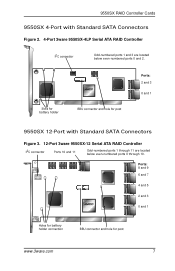
.... Slots for battery holder BBU connector and hole for post www.3ware.com 7 Ports: 8 and 9 6 and 7 4 and 5 2 and 3 0 and 1 Holes for battery holder connection BBU connector and hole for post Ports: 2 and 3 0 and 1 9550SX 12-Port with Standard SATA Connectors Figure 2. 4-Port 3ware 9550SX-4LP Serial ATA RAID Controller I2C connector Odd-numbered ports 1 and...
.... Slots for battery holder BBU connector and hole for post www.3ware.com 7 Ports: 8 and 9 6 and 7 4 and 5 2 and 3 0 and 1 Holes for battery holder connection BBU connector and hole for post Ports: 2 and 3 0 and 1 9550SX 12-Port with Standard SATA Connectors Figure 2. 4-Port 3ware 9550SX-4LP Serial ATA RAID Controller I2C connector Odd-numbered ports 1 and...
Quick Installation Guide
Page 21
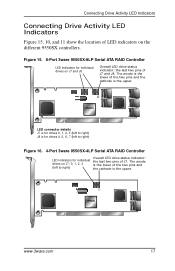
...anode is the lower of LED indicators on J7: 0, 1, 2, 3 (left to right) J8 is the upper. Figure 15. 8-Port 3ware 9550SX-8LP Serial ATA RAID Controller LED indicators for individual drives on J7 and J8 Overall LED drive status indicator: the last two pins of the... two pins and the cathode is for individual drives on the different 9550SX controllers. LED connector details J7 is for drives 0, 1, 2, 3 (left to right) Figure 16. 4-Port 3ware 9550SX-4LP Serial ATA RAID Controller LED indicators for drives 4, 5, 6, 7 (left to right) Overall LED drive status ...
...anode is the lower of LED indicators on J7: 0, 1, 2, 3 (left to right) J8 is the upper. Figure 15. 8-Port 3ware 9550SX-8LP Serial ATA RAID Controller LED indicators for individual drives on J7 and J8 Overall LED drive status indicator: the last two pins of the... two pins and the cathode is for individual drives on the different 9550SX controllers. LED connector details J7 is for drives 0, 1, 2, 3 (left to right) Figure 16. 4-Port 3ware 9550SX-4LP Serial ATA RAID Controller LED indicators for drives 4, 5, 6, 7 (left to right) Overall LED drive status ...
Quick Installation Guide
Page 24
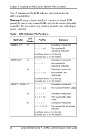
... any common ground to the anode pins on the controller. Chapter 1. Table 1: LED Indicator Pin Positions Controller LED Header Pin Pair Comment 9550SX-4LP J7 : : : : : Orientation Horizontal 9550SX-8LP J7 J8 0 1 2 3 All Port number/All (all activity indicator) k-cathode-minus is on the top a-anode-plus is...Port number/All (all activity indicator) k-cathode-minus is on the top a-anode-plus is on the controller. Installing an AMCC 3ware 9550SX RAID Controller Table 1 summarizes the LED indicator pin positions for the different controllers. Warning: If using a chassis that has a ...
... any common ground to the anode pins on the controller. Chapter 1. Table 1: LED Indicator Pin Positions Controller LED Header Pin Pair Comment 9550SX-4LP J7 : : : : : Orientation Horizontal 9550SX-8LP J7 J8 0 1 2 3 All Port number/All (all activity indicator) k-cathode-minus is on the top a-anode-plus is...Port number/All (all activity indicator) k-cathode-minus is on the top a-anode-plus is on the controller. Installing an AMCC 3ware 9550SX RAID Controller Table 1 summarizes the LED indicator pin positions for the different controllers. Warning: If using a chassis that has a ...
