Installation Guide
Page 3
...Drive Activity LED Indicators (Optional 21 Step 5. Table of this Guide iv Chapter 1. Connect the Cables to the Controller 16 Step 1 (Multi-lane Controllers). Installing Your 3ware RAID Controller 15 Tools You Need 15 Before You Start 15 Step 1 (9650SE-2LP). Connect the Cables ...to the SATA/SAS Drive Multi-Lane Backplane . 21 Step 4. Getting Started 1 Contents of Contents About this Package ...
...Drive Activity LED Indicators (Optional 21 Step 5. Table of this Guide iv Chapter 1. Connect the Cables to the Controller 16 Step 1 (Multi-lane Controllers). Installing Your 3ware RAID Controller 15 Tools You Need 15 Before You Start 15 Step 1 (9650SE-2LP). Connect the Cables ...to the SATA/SAS Drive Multi-Lane Backplane . 21 Step 4. Getting Started 1 Contents of Contents About this Package ...
Installation Guide
Page 17
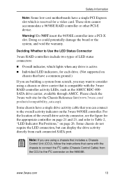
...9650SE controller into a PCI-X slot. Some chassis do not require the LED connection, but can connect to Table 2, "LED Indicator Pin Positions," on page 26. www.3ware.com 13 For the location of LED status connectors: „ Overall indicator, which is active. „ Individual LED indicators, for the appropriate controller on page 21... and 23, and refer to the overall activity indicator on the 3ware 9650SE controller. Doing so could potentially damage the board or the system, and void the...
...9650SE controller into a PCI-X slot. Some chassis do not require the LED connection, but can connect to Table 2, "LED Indicator Pin Positions," on page 26. www.3ware.com 13 For the location of LED status connectors: „ Overall indicator, which is active. „ Individual LED indicators, for the appropriate controller on page 21... and 23, and refer to the overall activity indicator on the 3ware 9650SE controller. Doing so could potentially damage the board or the system, and void the...
Installation Guide
Page 24
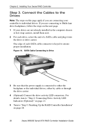
... Controller Step 3. Figure 14. Connecting Drive Activity LED Indicators (Optional)" on page 28. 20 3ware 9650SE Serial ATA RAID Controller Installation Guide If you are not already installed in the computer chassis or hot swap carriers, install them now. 2 For each... drives, either by cable or through the drive carrier. 4 (Optional) Connect the drive activity LED connectors. Finishing Up the RAID Controller Installation" on page 21. 5 Turn to ensure proper installation. One edge of each drive, select the end of a SATA cable and plug it into the drive or drive carrier...
... Controller Step 3. Figure 14. Connecting Drive Activity LED Indicators (Optional)" on page 28. 20 3ware 9650SE Serial ATA RAID Controller Installation Guide If you are not already installed in the computer chassis or hot swap carriers, install them now. 2 For each... drives, either by cable or through the drive carrier. 4 (Optional) Connect the drive activity LED connectors. Finishing Up the RAID Controller Installation" on page 21. 5 Turn to ensure proper installation. One edge of each drive, select the end of a SATA cable and plug it into the drive or drive carrier...
Installation Guide
Page 25
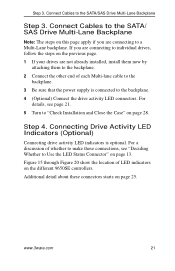
..."Deciding Whether to a Multi-Lane backplane. For a discussion of whether to the backplane. 4 (Optional) Connect the drive activity LED connectors. www.3ware.com 21 Connect Cables to the SATA/ SAS Drive Multi-Lane Backplane Note: The steps on this page apply if you are connecting to individual drives, follow ... them to the backplane. 2 Connect the other end of LED indicators on page 28. Additional detail about these connections, see page 21. 5 Turn to the SATA/SAS Drive Multi-Lane Backplane Step 3. Connect Cables to "Check Installation and Close the Case" on the different...
..."Deciding Whether to a Multi-Lane backplane. For a discussion of whether to the backplane. 4 (Optional) Connect the drive activity LED connectors. www.3ware.com 21 Connect Cables to the SATA/ SAS Drive Multi-Lane Backplane Note: The steps on this page apply if you are connecting to individual drives, follow ... them to the backplane. 2 Connect the other end of LED indicators on page 28. Additional detail about these connections, see page 21. 5 Turn to the SATA/SAS Drive Multi-Lane Backplane Step 3. Connect Cables to "Check Installation and Close the Case" on the different...
Installation Guide
Page 29
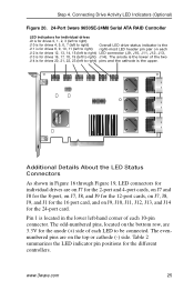
...odd-numbered pins, located on the top or cathode (-) side. www.3ware.com 25 Table 2 summarizes the LED indicator pin positions for the ... for the 16 port card, and on each 10-pin connector. Connecting Drive Activity LED Indicators (Optional) Figure 20. 24-Port 3ware 9650SE-24M8 Serial ATA RAID Controller LED indicators for individual drives J9 is for drives 0, 1, 2, 3 (left to right) J10 is...right) right-most LED header pin pair on J9, J10, J11, J12, J13, and J14 for drives 20, 21, 22, 23 (left to right) J14). Pin 1 is located in Figure 16 through Figure 19, LED connectors for...
...odd-numbered pins, located on the top or cathode (-) side. www.3ware.com 25 Table 2 summarizes the LED indicator pin positions for the ... for the 16 port card, and on each 10-pin connector. Connecting Drive Activity LED Indicators (Optional) Figure 20. 24-Port 3ware 9650SE-24M8 Serial ATA RAID Controller LED indicators for individual drives J9 is for drives 0, 1, 2, 3 (left to right) J10 is...right) right-most LED header pin pair on J9, J10, J11, J12, J13, and J14 for drives 20, 21, 22, 23 (left to right) J14). Pin 1 is located in Figure 16 through Figure 19, LED connectors for...
Installation Guide
Page 32
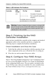
...Comment J14 : : : : : Orientation Horizontal 20 21 22 23 All Port number/All (all activity indicator) k-cathode-minus is on the top a-anode-plus is also available from the 3ware website at http://3ware.com/support/userdocs.asp. 28 3ware 9650SE Serial ATA RAID Controller Installation Guide Do not connect ...any common ground to the anode pins on the 3ware CD that the cables do not interfere with your ...
...Comment J14 : : : : : Orientation Horizontal 20 21 22 23 All Port number/All (all activity indicator) k-cathode-minus is on the top a-anode-plus is also available from the 3ware website at http://3ware.com/support/userdocs.asp. 28 3ware 9650SE Serial ATA RAID Controller Installation Guide Do not connect ...any common ground to the anode pins on the 3ware CD that the cables do not interfere with your ...

Installation Guide
Page 34
...height controllers (4-port and 8-port) and holes on the controller. Figure 21. Tools and equipment required „ Slot-head screwdriver „ Grounding strap „ Battery Backup Unit (BBU) and battery „ 3ware 9650SE series controller Installation Overview The Battery Backup Unit (BBU) is ready for...These pieces attach to the controller at the points illustrated in Figures 21 through 23: a Clips on the battery module match to receptacle on the BBU a) Clips b) BBU connector c) Post 30 3ware 9650SE Serial ATA RAID Controller Installation Guide Wait to plug the battery into ...
...height controllers (4-port and 8-port) and holes on the controller. Figure 21. Tools and equipment required „ Slot-head screwdriver „ Grounding strap „ Battery Backup Unit (BBU) and battery „ 3ware 9650SE series controller Installation Overview The Battery Backup Unit (BBU) is ready for...These pieces attach to the controller at the points illustrated in Figures 21 through 23: a Clips on the battery module match to receptacle on the BBU a) Clips b) BBU connector c) Post 30 3ware 9650SE Serial ATA RAID Controller Installation Guide Wait to plug the battery into ...