AIWA AM-HX50 Support and Manuals
Get Help and Manuals for this AIWA item
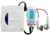
View All Support Options Below
Free AIWA AM-HX50 manuals!
Problems with AIWA AM-HX50?
Ask a Question
Free AIWA AM-HX50 manuals!
Problems with AIWA AM-HX50?
Ask a Question
Popular AIWA AM-HX50 Manual Pages
Service Manual - Page 1
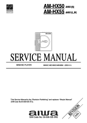
S/M Code No. 09-999-335-5R2
REVISDIAOTAN
AM-HX50 AHK1(S) AM-HX55 AHK1(L,W)
SERVICE MANUAL
MINIDISC PLAYER
BASIC MD MECHANISM : ZZG-5 A
This Service Manual is the "Revision Publishing" and replaces "Simple Manual" (S/M Code No.09-999-335-5T2).
Service Manual - Page 2
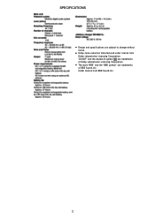
SPECIFICATIONS
• Design and specifications are trademarks of BBE Sound,Inc. Under license from Dolby Laboratories Licensing Corporation. "DOLBY" and the double-D symbol are trademarks of Dolby Laboratories Licensing Corporation.
&#...
Service Manual - Page 3
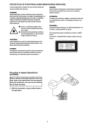
... LUOKAN 1 LASER LAITE KLASS 1 LASER APPARAT
Precaution to replace Optical block (KLR2000)
Body or clothes electrostatic potential could ruin... interlocks defeated avoid exposure to follow carefully the instructions below when servicing. Laiteen Käyttäminen muulla kuin ...BLOCK. PROTECTION OF EYES FROM LASER BEAM DURING SERVICING
This set employs laser. WARNING! Be sure ground body and...
Service Manual - Page 4
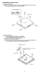
...The BAT-CONTACT + is attached, be careful of the arrow. * When attaching the PANEL, BOT, set the KNOB, SL HOLD. Removing the MAIN C.B 1) Connect the shorting lands of the pickup by a... Remove the FFC of the CN300, CN700 and CN100. 3) Remove the screw A*3 and screw B*1. 4) Remove the battery lid and remove the MAIN C.B, while being careful of the BAT-CONTACT +. * When the MAIN C.B is attached ...
Service Manual - Page 15
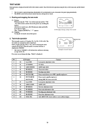
... displayed. key and execute/stop the test mode, turn on the LCD of test mode
2. If an error occurs during startup of the remote control. MODE NO.
During DISC IN, focus servo ON
7
07
Laser...meaning. (except for No.13). TEST MODE
Each operation is displayed on the power (by installing the battery). LCD display
Contents
0
00
Laser $XX
Laser power adjustment value
1
01
VC $XXXX...
Service Manual - Page 16
...
"LDPP $XX"
GRV laser power
"LDPG $XX"
TR NO.
LDPP
$50
PIT
TR NO. T.
L D PG
$78
GRV
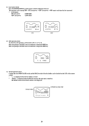
(2) Sled operation check To check the sled operation, set the mode to No. 0, or 5 to the DISC inner circumference using the F-SKIP key. En g i nee r M
20 Move the pickup to 12.
Service Manual - Page 17
... DLE
(2) Stopping To stop the adjustment mode, turn on the power (by installing the battery). After checking the startup, press the STOP key to display "IDLE". Starting and... PIT disc (pre-mastered disc): TEST DISC (TGYS1) GRV disc (MO disc): SONY MDW-74 (fully pre-recorded disc)
(4) Precautions • If the disc is checked... adjust manually. • If "NO ADJ" appears during normal use .
Service Manual - Page 18
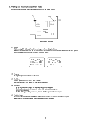
... to initialize the EEPROM.
will appear during adjustment, it means that the adjustment was suspended due to an error.
5. TR NO. 4. E P I NT OK (2) Sled operation check
While "IDLE" is displayed,....) After "AUTO ADJ H" appears on the LCD of the remote control, "COMPLETE" appears.
(2) GRV disc (SONY MDW-74) Insert a disc and press the "PLAY" key. (Be careful of the direction of the remote ...
Service Manual - Page 19
...I
FOK signal input.
23
Connected to GND.
- 3 [MHz] clock.
- Connected to VDD.
-
I
I
A/D input of motor driver. O Serial data output to GND.
I
Standby cancel signal input from LC89641. I
O Not used (L output).
I
Interrupt input at H).... output for adjustment of band-pass filter of sled.
I
A/D input of battery voltage. I
A/D input of main unit KEY.
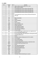
Service Manual - Page 22
.... O
O
O Frame sync detection signal output terminal. O Focus OK signal output terminal.
I
connected.
-
The terminal to which external bias resistor setting current charge pump of VCEC. The terminal to which external bias resistor setting oscillation frequency of VCEC is I
Data input terminal for test.
26 Ground terminal for CPU interface.
Low: sync, Hi...
Service Manual - Page 23
...input terminal.
I
PEAK signal input terminal. I
Center voltage input terminal.
- I
System reset. O Disc mode switching output. I
Focus error signal input terminal. I
Tracking error signal input terminal. The terminal to which external bias resistor setting of main beam, is connected.
I /O
Description
O HF signal slice level output terminal. Power supply terminal for...
Service Manual - Page 26
... by J pin.
I
-
High = Track is chain of pits, Low = Track is output from this terminal. The terminal to which pass-through capacitor for laser power setting. O Focus error signal output pin.
RF system ground pin.
I
Offset adjustment pin of FE signal. O APC circuit output pin.
-
I
Pin for pickup photo diode connection.
O 1/2 VCC...
Service Manual - Page 27
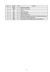
... 44 45 46 47 48
Pin Name RFVCC ADIPCR
NC WOO WOI SETR CAD BWCT SLEEP
I
Wobble signal input pin. Not used. I
Sleep mode pin. I
Setting pin for band-pass filter.
-
Service Manual - Page 29
...1/1
3
B 4
J701 ZZG-5 A
P.C.B
C 5
P.C.B
6 P.C.B
A
b c
7
F
10
11
12
B
D
13 14
A 8
9
a B
1
E
15
16 17 18
B b
D
E
E
19
E F
c
E
20 E
E
33
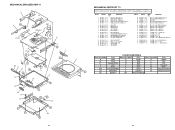
MECHANICAL PARTS LIST 1/1
REF. KANRI NO.
DESCRIPTION
16 8A-HM3-008-110 16 8A-HM4-011-110 17 8A-HM3-006-010 18 8A-HM3-007-010... Blue
LL
Light Blue
GT
Transparent Green
LD
Dark Blue
DT
Transparent Orange
34 NO
PART NO.
Service Manual - Page 30

...-393-010 C 87-067-569-010 D 87-067-511-010
S-SCREW,VBT+1.4-3 SCREW +1.4-1.4 POLY WASHER 0.83-2.5-0.25 SCREW,V+1.4-2 BK
MD MECHANISM EXPLODED VIEW 2/2
1 2 P.C.B 3 4 5 6
MD MECHANISM PARTS LIST 2/2
REF. DESCRIPTION
1 8Z-ZS2-214-010 2 8Z-ZS2-204-010 3 8Z-ZS2-201-010 4 8Z-ZS2-213-010 5 8Z-ZS2-208-010
PLATE,BASE...
AIWA AM-HX50 Reviews
We have not received any reviews for AIWA yet.