
User Manual
Page 6
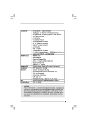
Supports Untied Overclocking Technology (see CAUTION 7) - ASRock U-COP (see CAUTION 3) - DirectX 8.0 VGA - Cmedia 9761A 5.1 channel audio CODEC - Supports Wake-On-LAN ASRock I /O - Micro ATX Form Factor: 9.6-in x 8.0-in, 24.4 cm x 20.3 cm - LGA 775 for internal graphics - Southbridge: Intel® ICH5 - Support DDR400/333/266 (see CAUTION 8) - 1 x ...
Supports Untied Overclocking Technology (see CAUTION 7) - ASRock U-COP (see CAUTION 3) - DirectX 8.0 VGA - Cmedia 9761A 5.1 channel audio CODEC - Supports Wake-On-LAN ASRock I /O - Micro ATX Form Factor: 9.6-in x 8.0-in, 24.4 cm x 20.3 cm - LGA 775 for internal graphics - Southbridge: Intel® ICH5 - Support DDR400/333/266 (see CAUTION 8) - 1 x ...
User Manual
Page 7
... AMI BIOS - It should be done at your system. CD in the BIOS, applying Untied Overclocking Technology, or using the thirdparty overclocking tools. Front panel audio connector - 2 x USB 2.0 headers (support 4 USB 2.0 ports; 2 of your own risk and expense. CPU Fan Tachometer - We are shared with overclocking, including adjusting the setting in...
... AMI BIOS - It should be done at your system. CD in the BIOS, applying Untied Overclocking Technology, or using the thirdparty overclocking tools. Front panel audio connector - 2 x USB 2.0 headers (support 4 USB 2.0 ports; 2 of your own risk and expense. CPU Fan Tachometer - We are shared with overclocking, including adjusting the setting in...
User Manual
Page 9
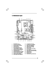
...: RJ-45 USB 2.0 T: USB0 B: USB1 USB 2.0 T: USB2 B: USB3 USB 2.0 1 T: USB4 B: USB5 IDE2 Intel 865G Chipset 775i65G USB4_5 Super I/O ATXPWR1 4Mb BIOS PCI LAN CD1 AUX1 AUDIO CODEC AUDIO1 1 JR1 JL1 AGP8X 1.5V_AGP1 IDE1 RoHS CHA_FAN1 SATA PCI 1 PCI 2 USB2.0 PCI 3 5.1CH FLOPPY1 COM1 AMR1 1 Intel ...Blue) 19 Floppy Connector (FLOPPY1) 20 Serial Port Connector (COM1) 21 AMR Slot (AMR1) 22 Front Panel Audio Header (AUDIO1) 23 JR1 / JL1 Jumpers 24 Internal Audio Connector: CD1 (Black) 25 Internal Audio Connector: AUX1 (White) 26 PCI Slots (PCI1- 3) 27 AGP Slot (1.5V_AGP1) 28 BIOS FWH Chip ...
...: RJ-45 USB 2.0 T: USB0 B: USB1 USB 2.0 T: USB2 B: USB3 USB 2.0 1 T: USB4 B: USB5 IDE2 Intel 865G Chipset 775i65G USB4_5 Super I/O ATXPWR1 4Mb BIOS PCI LAN CD1 AUX1 AUDIO CODEC AUDIO1 1 JR1 JL1 AGP8X 1.5V_AGP1 IDE1 RoHS CHA_FAN1 SATA PCI 1 PCI 2 USB2.0 PCI 3 5.1CH FLOPPY1 COM1 AMR1 1 Intel ...Blue) 19 Floppy Connector (FLOPPY1) 20 Serial Port Connector (COM1) 21 AMR Slot (AMR1) 22 Front Panel Audio Header (AUDIO1) 23 JR1 / JL1 Jumpers 24 Internal Audio Connector: CD1 (Black) 25 Internal Audio Connector: AUX1 (White) 26 PCI Slots (PCI1- 3) 27 AGP Slot (1.5V_AGP1) 28 BIOS FWH Chip ...
User Manual
Page 17
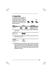
2.7 Jumpers Setup The illustration shows how jumpers are short, both the front panel and the rear panel audio connectors can work. When the jumper cap is placed on pins, the jumper is "Open". Jumper Setting Description PS2_USB_PWR1 1_2 (see p.9 No. 1) Short pin2, pin3 ...
2.7 Jumpers Setup The illustration shows how jumpers are short, both the front panel and the rear panel audio connectors can work. When the jumper cap is placed on pins, the jumper is "Open". Jumper Setting Description PS2_USB_PWR1 1_2 (see p.9 No. 1) Short pin2, pin3 ...

User Manual
Page 19
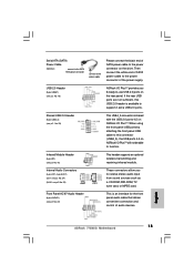
... wireless transmitting and receiving infrared module. Front Panel AC'97 Audio Header (8-pin AUDIO1) (see p.9 No. 18) USB_PWR P-7 P+7 GND DUMMY 1 GND P+6 P-6 USB_PWR ASRock I/O PlusTM accommodates 6 default USB 2.0 ports. These connectors allow you to receive stereo audio input from sound sources such as a CD-ROM, DVD-ROM..., TV tuner card, or MPEG card. If those USB 2.0 ports on ASRock I/O PlusTM. When using the front panel USB ports by attaching the ...
... wireless transmitting and receiving infrared module. Front Panel AC'97 Audio Header (8-pin AUDIO1) (see p.9 No. 18) USB_PWR P-7 P+7 GND DUMMY 1 GND P+6 P-6 USB_PWR ASRock I/O PlusTM accommodates 6 default USB 2.0 ports. These connectors allow you to receive stereo audio input from sound sources such as a CD-ROM, DVD-ROM..., TV tuner card, or MPEG card. If those USB 2.0 ports on ASRock I/O PlusTM. When using the front panel USB ports by attaching the ...
User Manual
Page 20
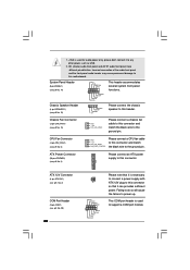
...Connector (3-pin CHA_FAN1) (see p.9 No. 20) 20 RRXD1 DDTR#1 DDSR#1 CCTS#1 1 RRI#1 RRTS#1 GND TTXD1 DDCD#1 Please note that it is used for audio power only, please don't connect it can provides sufficient power. ATX 12V Connector (4-pin ATX12V1) (see p.9, No. 2) COM Port Header (9-pin COM1) (see ...p.9 No. 15) 1 SPEAKER DUMMY DUMMY +5V Please connect the chassis speaker to this connector. Incorrect connection of the audio front panel and the front panel audio header may cause permanent damage to this connector and match the black wire to this header. This COM port header is ...
...Connector (3-pin CHA_FAN1) (see p.9 No. 20) 20 RRXD1 DDTR#1 DDSR#1 CCTS#1 1 RRI#1 RRTS#1 GND TTXD1 DDCD#1 Please note that it is used for audio power only, please don't connect it can provides sufficient power. ATX 12V Connector (4-pin ATX12V1) (see p.9, No. 2) COM Port Header (9-pin COM1) (see ...p.9 No. 15) 1 SPEAKER DUMMY DUMMY +5V Please connect the chassis speaker to this connector. Incorrect connection of the audio front panel and the front panel audio header may cause permanent damage to this connector and match the black wire to this header. This COM port header is ...
User Manual
Page 26
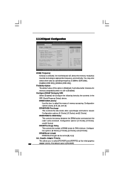
Graphic Adapter Priority Graphics Aperture Size [PCI / AGP] [64MB] OnBoard LAN OnBoard AC'97 Audio OnBoard MC'97 Modem [Enabled] [Auto] [Auto] Options 133MHz 166MHz 200MHz Auto (DDR266) (DDR333) (DDR400) +F1 F9 F10 ESC Select Screen Select Item Change Option ...
Graphic Adapter Priority Graphics Aperture Size [PCI / AGP] [64MB] OnBoard LAN OnBoard AC'97 Audio OnBoard MC'97 Modem [Enabled] [Auto] [Auto] Options 133MHz 166MHz 200MHz Auto (DDR266) (DDR333) (DDR400) +F1 F9 F10 ESC Select Screen Select Item Change Option ...

User Manual
Page 27
... [Auto], [Enabled] or [Disabled] for the onboard MC'97 Modem feature. OnBoard MC'97 Modem Select [Auto] or [Disabled] for the onboard AC'97 Audio feature. VCCM +2.7V Voltage This option allows you to set VDDQ +1.58V Voltage. The default value is [Auto]. The default value is [Auto]. Configuration options: [...
... [Auto], [Enabled] or [Disabled] for the onboard MC'97 Modem feature. OnBoard MC'97 Modem Select [Auto] or [Disabled] for the onboard AC'97 Audio feature. VCCM +2.7V Voltage This option allows you to set VDDQ +1.58V Voltage. The default value is [Auto]. The default value is [Auto]. Configuration options: [...

Quick Installation Guide
Page 2
... Floppy Connector (FLOPPY1) 20 Serial Port Connector (COM1) 21 AMR Slot (AMR1) 22 Front Panel Audio Header (AUDIO1) 23 JR1 / JL1 Jumpers 24 Internal Audio Connector: CD1 (Black) 25 Internal Audio Connector: AUX1 (White) 26 PCI Slots (PCI1- 3) 27 AGP Slot (1.5V_AGP1) 28 BIOS FWH Chip 29 Shared USB 2.0 Header (USB4_5, Blue) 2 ASRock 775i65G Motherboard
... Floppy Connector (FLOPPY1) 20 Serial Port Connector (COM1) 21 AMR Slot (AMR1) 22 Front Panel Audio Header (AUDIO1) 23 JR1 / JL1 Jumpers 24 Internal Audio Connector: CD1 (Black) 25 Internal Audio Connector: AUX1 (White) 26 PCI Slots (PCI1- 3) 27 AGP Slot (1.5V_AGP1) 28 BIOS FWH Chip 29 Shared USB 2.0 Header (USB4_5, Blue) 2 ASRock 775i65G Motherboard

Quick Installation Guide
Page 5
...Boot Failure Guard (B.F.G.) - 3 x PCI slots - 1 x AGP slot for external graphics (see CAUTION 8) - 1 x AMR slot - Speed: 10/100 Ethernet - ASRock U-COP (see CAUTION 5) - Cmedia 9761A 5.1 channel audio CODEC - FSB 800/533 MHz for Intel® CoreTM 2 Extreme / CoreTM 2 Duo / Pentium® XE / Pentium® D / Pentium® 4 / Celeron&#...ICH5 - Dual Channel DDR Memory Technology (see CAUTION 6) - CPU Frequency Stepless Control (see CAUTION 4) - 2 x DDR DIMM slots - DirectX 8.0 VGA - Audio Jack: Line In / Line Out / Microphone English 5 ASRock 775i65G Motherboard
...Boot Failure Guard (B.F.G.) - 3 x PCI slots - 1 x AGP slot for external graphics (see CAUTION 8) - 1 x AMR slot - Speed: 10/100 Ethernet - ASRock U-COP (see CAUTION 5) - Cmedia 9761A 5.1 channel audio CODEC - FSB 800/533 MHz for Intel® CoreTM 2 Extreme / CoreTM 2 Duo / Pentium® XE / Pentium® D / Pentium® 4 / Celeron&#...ICH5 - Dual Channel DDR Memory Technology (see CAUTION 6) - CPU Frequency Stepless Control (see CAUTION 4) - 2 x DDR DIMM slots - DirectX 8.0 VGA - Audio Jack: Line In / Line Out / Microphone English 5 ASRock 775i65G Motherboard

Quick Installation Guide
Page 6
... WHQL WARNING Please realize that there is a certain risk involved with USB4_5) (see CAUTION 9) - 4Mb AMI BIOS - English 6 ASRock 775i65G Motherboard Overclocking may affect your system stability, or even cause damage to the components and devices of them are not responsible for "RAID...We are shared with overclocking, including adjusting the setting in the BIOS, applying Untied Overclocking Technology, or using the thirdparty overclocking tools. Front panel audio connector - 2 x USB 2.0 headers (support 4 USB 2.0 ports; 2 of your own risk and expense. CPU/Chassis FAN connector - ...
... WHQL WARNING Please realize that there is a certain risk involved with USB4_5) (see CAUTION 9) - 4Mb AMI BIOS - English 6 ASRock 775i65G Motherboard Overclocking may affect your system stability, or even cause damage to the components and devices of them are not responsible for "RAID...We are shared with overclocking, including adjusting the setting in the BIOS, applying Untied Overclocking Technology, or using the thirdparty overclocking tools. Front panel audio connector - 2 x USB 2.0 headers (support 4 USB 2.0 ports; 2 of your own risk and expense. CPU/Chassis FAN connector - ...

Quick Installation Guide
Page 13
... Short pin2, pin3 to clear the data in CMOS includes system setup information such as system password, date, time, and system setup parameters. English 13 ASRock 775i65G Motherboard The data in CMOS. If no jumper cap is placed on CLRCMOS0 for PS/2 or USB wake up events. JR1(see p.2 No. 23) JL1.... Clear CMOS (CLRCMOS0, 2-pin jumper) (see p.2 No. 23) Note: If the JL1 and JR1 jumpers are short, both the front panel and the rear panel audio connectors can work. The illustration shows a 3-pin jumper whose pin1 and pin2 are setup.
... Short pin2, pin3 to clear the data in CMOS includes system setup information such as system password, date, time, and system setup parameters. English 13 ASRock 775i65G Motherboard The data in CMOS. If no jumper cap is placed on CLRCMOS0 for PS/2 or USB wake up events. JR1(see p.2 No. 23) JL1.... Clear CMOS (CLRCMOS0, 2-pin jumper) (see p.2 No. 23) Note: If the JL1 and JR1 jumpers are short, both the front panel and the rear panel audio connectors can work. The illustration shows a 3-pin jumper whose pin1 and pin2 are setup.
Quick Installation Guide
Page 15
... you 6 ready-to the power connector on the rear panel. English 15 ASRock 775i65G Motherboard USB 2.0 Header (9-pin USB67) (see p.2 No. 18) ASRock I /O PlusTM. Shared USB 2.0 Header (9-pin USB4_5) (see p.2 No. 22) This is an interface for the front panel audio cable that allows convenient connection and control of SATA power cable to -use...
... you 6 ready-to the power connector on the rear panel. English 15 ASRock 775i65G Motherboard USB 2.0 Header (9-pin USB67) (see p.2 No. 18) ASRock I /O PlusTM. Shared USB 2.0 Header (9-pin USB4_5) (see p.2 No. 22) This is an interface for the front panel audio cable that allows convenient connection and control of SATA power cable to -use...

Quick Installation Guide
Page 16
...(see p.2 No. 13) Please connect the chassis fan cable to this connector so that it to this motherboard, please connect it is used for audio power only, please don't connect it can work successfully even without the fan speed control function. CPU Fan Connector 1 (4-pin CPU_FAN1) 2 3 ... black wire to this connector. Incorrect connection of the audio front panel and the front panel audio header may cause permanent damage to the ground pin. ATX 12V Connector Please note that it to power up. 16 ASRock 775i65G Motherboard English Chassis Fan Connector (3-pin CHA_FAN1) (see...
...(see p.2 No. 13) Please connect the chassis fan cable to this connector so that it to this motherboard, please connect it is used for audio power only, please don't connect it can work successfully even without the fan speed control function. CPU Fan Connector 1 (4-pin CPU_FAN1) 2 3 ... black wire to this connector. Incorrect connection of the audio front panel and the front panel audio header may cause permanent damage to the ground pin. ATX 12V Connector Please note that it to power up. 16 ASRock 775i65G Motherboard English Chassis Fan Connector (3-pin CHA_FAN1) (see...


