
User Manual
Page 3
... 5 1.2 Specifications 6 1.3 Motherboard Layout 8 1.4 ASRock 8CH I/O 9 2 Installation 10 2.1 Screw Holes 10 2.2 Pre-installation Precautions 10 2.3 CPU Installation 11 2.4 Installation of Heatsink and CPU fan 13 2.5 Installation of Memory Modules (DIMM 14 2.6 Expansion Slots 15 2.7 Surround Display Feature 16 2.8 Jumpers Setup 16 2.9 Onboard Headers and Connectors 17 2.10 Serial ATA (SATA) Hard Disks Installation...
... 5 1.2 Specifications 6 1.3 Motherboard Layout 8 1.4 ASRock 8CH I/O 9 2 Installation 10 2.1 Screw Holes 10 2.2 Pre-installation Precautions 10 2.3 CPU Installation 11 2.4 Installation of Heatsink and CPU fan 13 2.5 Installation of Memory Modules (DIMM 14 2.6 Expansion Slots 15 2.7 Surround Display Feature 16 2.8 Jumpers Setup 16 2.9 Onboard Headers and Connectors 17 2.10 Serial ATA (SATA) Hard Disks Installation...

User Manual
Page 5
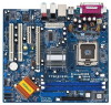
... updated version will be available on ASRock website as well. ASRock website http://www.asrock.com 1.1 Package Contents ASRock 775i915PL-M Motherboard (Micro ATX Form Factor: 9.6-in x 8.6-in, 24.4 cm x 21.8 cm) ASRock 775i915PL-M Quick Installation Guide ASRock 775i915PL-M Support CD (including LGA 775...It delivers excellent performance with robust design conforming to ASRock's commitment to change without further notice. Chapter 1 Introduction Thank you for a 3.5-in Floppy Drive One Serial ATA (SATA) Data Cable One Serial ATA (SATA) HDD Power Cable (Optional) One ASRock 8CH I/O 5
... updated version will be available on ASRock website as well. ASRock website http://www.asrock.com 1.1 Package Contents ASRock 775i915PL-M Motherboard (Micro ATX Form Factor: 9.6-in x 8.6-in, 24.4 cm x 21.8 cm) ASRock 775i915PL-M Quick Installation Guide ASRock 775i915PL-M Support CD (including LGA 775...It delivers excellent performance with robust design conforming to ASRock's commitment to change without further notice. Chapter 1 Introduction Thank you for a 3.5-in Floppy Drive One Serial ATA (SATA) Data Cable One Serial ATA (SATA) HDD Power Cable (Optional) One ASRock 8CH I/O 5
User Manual
Page 6
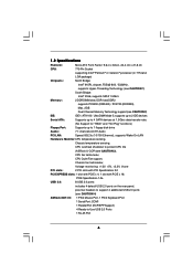
...: COM1 1 Parallel Port (ECP/EPP Support) 4 Ready-to protect CPU life (ASRock U-COP)(see CAUTION 2) IDE: IDE1: ATA 100 / Ultra DMA Mode 5, supports up to 2 IDE devices Serial ATA: Supports up to 4 SATA devices at 1.5Gb/s data transfer rate. (No Support for "RAID" and "Hot...North Bridge: Intel® 915PL chipset, FSB @ 800 / 533MHz, supports Hyper-Threading Technology (see CAUTION 1) South Bridge: Intel® ICH6, supports SATA 1.5Gb/s Memory: 2 DDR DIMM slots: DDR1 and DDR2 supports PC3200 (DDR400) / PC2700 (DDR333), Max. 2GB Dual Channel Memory Technology support(see ...
...: COM1 1 Parallel Port (ECP/EPP Support) 4 Ready-to protect CPU life (ASRock U-COP)(see CAUTION 2) IDE: IDE1: ATA 100 / Ultra DMA Mode 5, supports up to 2 IDE devices Serial ATA: Supports up to 4 SATA devices at 1.5Gb/s data transfer rate. (No Support for "RAID" and "Hot...North Bridge: Intel® 915PL chipset, FSB @ 800 / 533MHz, supports Hyper-Threading Technology (see CAUTION 1) South Bridge: Intel® ICH6, supports SATA 1.5Gb/s Memory: 2 DDR DIMM slots: DDR1 and DDR2 supports PC3200 (DDR400) / PC2700 (DDR333), Max. 2GB Dual Channel Memory Technology support(see ...

User Manual
Page 8
... CD1 7.1CH PCI LAN AUDIO CODEC AUDIO1 1 JR1 JL1 ATXPWR1 Intel 915PL Chipset CHA_FAN1 SATA PCIE1 IDE1 PCIE2 ` PCI 1 PCI 2 USB2.0 IntIeClH6 CMOS Battery SPEAKER1 1 USB45 USB67 1 1 CLRCMOS1 1 USB45 PANEL1 PLED PWRBTN 1 HDLED RESET SATA1 SATA2 SATA3 SATA4 775i915PL-M PCI EXPRESS 24.4cm (9.6 in) 8 9 10 11 12 13 22 21 20 19...
... CD1 7.1CH PCI LAN AUDIO CODEC AUDIO1 1 JR1 JL1 ATXPWR1 Intel 915PL Chipset CHA_FAN1 SATA PCIE1 IDE1 PCIE2 ` PCI 1 PCI 2 USB2.0 IntIeClH6 CMOS Battery SPEAKER1 1 USB45 USB67 1 1 CLRCMOS1 1 USB45 PANEL1 PLED PWRBTN 1 HDLED RESET SATA1 SATA2 SATA3 SATA4 775i915PL-M PCI EXPRESS 24.4cm (9.6 in) 8 9 10 11 12 13 22 21 20 19...

User Manual
Page 17
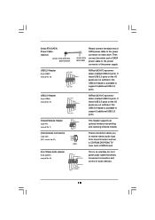
... vendor for internal storage devices. Do NOT place jumper caps over the headers and connectors will cause permanent damage of the SATA data cable can be connected to the instruction of the connector. Placing jumper caps over these headers and connectors. FDD connector... (33-pin FLOPPY1) (see p.8 No. 14) SATA1 SATA2 SATA3 SATA4 These four Serial ATA (SATA) connectors support SATA data cables for the details. Serial ATA Connectors (SATA1: see p.8 No. 17) (SATA2: see p.8 No. 16) (SATA3: see p.8 No. 15...
... vendor for internal storage devices. Do NOT place jumper caps over the headers and connectors will cause permanent damage of the SATA data cable can be connected to the instruction of the connector. Placing jumper caps over these headers and connectors. FDD connector... (33-pin FLOPPY1) (see p.8 No. 14) SATA1 SATA2 SATA3 SATA4 These four Serial ATA (SATA) connectors support SATA data cables for the details. Serial ATA Connectors (SATA1: see p.8 No. 17) (SATA2: see p.8 No. 16) (SATA3: see p.8 No. 15...
User Manual
Page 18
Then connect the white end of SATA power cable to the power connector of SATA power cable to the power connector on each drive. Front Panel Audio Header (9-pin AUDIO1) (see p.8 No. 27) IRTX +5V DUMMY 1 GND IRRX CD-R GND GND CD-L CD1 ASRock 8CH I /O panel are not sufficient, this ... IR1) (see p.8 No. 7) Internal Audio Connectors (4-pin CD1) (CD1: see p.8 No. 23) GND +5VA BACKOUT-R BACKOUT-L 1 A U D - Serial ATA (SATA) Power Cable (Optional) connect to the SATA HDD power connector connect to the power supply Please connect the black end of the power supply. R MIC-POWER MIC This is...
Then connect the white end of SATA power cable to the power connector of SATA power cable to the power connector on each drive. Front Panel Audio Header (9-pin AUDIO1) (see p.8 No. 27) IRTX +5V DUMMY 1 GND IRRX CD-R GND GND CD-L CD1 ASRock 8CH I /O panel are not sufficient, this ... IR1) (see p.8 No. 7) Internal Audio Connectors (4-pin CD1) (CD1: see p.8 No. 23) GND +5VA BACKOUT-R BACKOUT-L 1 A U D - Serial ATA (SATA) Power Cable (Optional) connect to the SATA HDD power connector connect to the power supply Please connect the black end of the power supply. R MIC-POWER MIC This is...

User Manual
Page 20
...motherboard adopts Intel ICH6 south bridge chipset that supports Serial ATA (SATA) hard disks. STEP 1: Install the SATA hard disks into the drive bays of the SATA data cable to the SATA hard disk. 20 This section will guide you to the SATA hard disk. STEP 3: Connect one end of your chassis. STEP... 2: Connect the SATA power cable to install the SATA hard disks. You may install SATA hard disks on this motherboard...
...motherboard adopts Intel ICH6 south bridge chipset that supports Serial ATA (SATA) hard disks. STEP 1: Install the SATA hard disks into the drive bays of the SATA data cable to the SATA hard disk. 20 This section will guide you to the SATA hard disk. STEP 3: Connect one end of your chassis. STEP... 2: Connect the SATA power cable to install the SATA hard disks. You may install SATA hard disks on this motherboard...

User Manual
Page 27
ATA/IDE Configuration Please select [Compatible] when you to select between [SATA 1, SATA 2, SATA 3, SATA 4], and [IDE 1, SATA 2, SATA 4]. Set [Enhanced] when Native OS (Win2000 / XP) is used with legacy OS. [SATA 1, SATA 2, SATA 3, SATA 4] [IDE 1, SATA 2, SATA 4] Master SATA1, SATA2 SATA2 Slave SATA3, SATA4 SATA4 27 When [Compatible] ...off mode. RTC Alarm Power On Use this item to enable or disable PS/2 keyboard to choose [SATA 1, SATA 2, SATA 3, SATA 4], or [IDE 1, SATA 2, SATA 4] when the installed device is used . +F1 F9 F10 ESC Select Screen Select Item Change ...
ATA/IDE Configuration Please select [Compatible] when you to select between [SATA 1, SATA 2, SATA 3, SATA 4], and [IDE 1, SATA 2, SATA 4]. Set [Enhanced] when Native OS (Win2000 / XP) is used with legacy OS. [SATA 1, SATA 2, SATA 3, SATA 4] [IDE 1, SATA 2, SATA 4] Master SATA1, SATA2 SATA2 Slave SATA3, SATA4 SATA4 27 When [Compatible] ...off mode. RTC Alarm Power On Use this item to enable or disable PS/2 keyboard to choose [SATA 1, SATA 2, SATA 3, SATA 4], or [IDE 1, SATA 2, SATA 4] when the installed device is used . +F1 F9 F10 ESC Select Screen Select Item Change ...
