
User Manual
Page 8
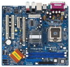
... IDE1 PCIE2 ` PCI 1 PCI 2 USB2.0 IntIeClH6 CMOS Battery SPEAKER1 1 USB45 USB67 1 1 CLRCMOS1 1 USB45 PANEL1 PLED PWRBTN 1 HDLED RESET SATA1 SATA2 SATA3 SATA4 775i915PL-M PCI EXPRESS 24.4cm (9.6 in) 8 9 10 11 12 13 22 21 20 19 18 17 161514 1 PS2_USB_PWR1 Jumper 2 ATX 12V Connector (ATX12V1...Speaker Header (SPEAKER 1) 14 Fourth Serial ATA Connector (SATA4, black) 15 Third Serial ATA Connector (SATA3, black) 16 Secondary Serial ATA Connector (SATA2, blue) 17 Primary Serial ATA Connector (SATA1, blue) 18 System Panel Header (PANEL1) 19 USB 2.0 Header (USB67, Blue) 20 Clear CMOS...
... IDE1 PCIE2 ` PCI 1 PCI 2 USB2.0 IntIeClH6 CMOS Battery SPEAKER1 1 USB45 USB67 1 1 CLRCMOS1 1 USB45 PANEL1 PLED PWRBTN 1 HDLED RESET SATA1 SATA2 SATA3 SATA4 775i915PL-M PCI EXPRESS 24.4cm (9.6 in) 8 9 10 11 12 13 22 21 20 19 18 17 161514 1 PS2_USB_PWR1 Jumper 2 ATX 12V Connector (ATX12V1...Speaker Header (SPEAKER 1) 14 Fourth Serial ATA Connector (SATA4, black) 15 Third Serial ATA Connector (SATA3, black) 16 Secondary Serial ATA Connector (SATA2, blue) 17 Primary Serial ATA Connector (SATA1, blue) 18 System Panel Header (PANEL1) 19 USB 2.0 Header (USB67, Blue) 20 Clear CMOS...

User Manual
Page 15
... make necessary hardware settings for PCI Express cards with x16 lane width graphics cards. Keep the screws for PCI Express cards, such as GigaLAN card, SATA2 card, etc. Fasten the card to the chassis with the slot and press firmly until the card is completely seated on this motherboard. Step 2. Step...
... make necessary hardware settings for PCI Express cards with x16 lane width graphics cards. Keep the screws for PCI Express cards, such as GigaLAN card, SATA2 card, etc. Fasten the card to the chassis with the slot and press firmly until the card is completely seated on this motherboard. Step 2. Step...

User Manual
Page 17
... 1.5 Gb/s data transfer rate. Placing jumper caps over these headers and connectors. Serial ATA Connectors (SATA1: see p.8 No. 17) (SATA2: see p.8 No. 16) (SATA3: see p.8 No. 15) (SATA4: see p.8 No. 14) SATA1 SATA2 SATA3 SATA4 These four Serial ATA (SATA) connectors support SATA data cables for the details. The current SATA interface...
... 1.5 Gb/s data transfer rate. Placing jumper caps over these headers and connectors. Serial ATA Connectors (SATA1: see p.8 No. 17) (SATA2: see p.8 No. 16) (SATA3: see p.8 No. 15) (SATA4: see p.8 No. 14) SATA1 SATA2 SATA3 SATA4 These four Serial ATA (SATA) connectors support SATA data cables for the details. The current SATA interface...

User Manual
Page 27
...to enable or disable PS/2 keyboard to turn on the system. 3.3.4 IDE Configuration BIOS SETUP UTILITY Advanced IDE Configuration ATA/IDE Configuration SATA1 SATA2 SATA3 SATA4 IDE1 Master IDE1 Slave [Enhanced] [Hard Disk] [Not Detected] [Not Detected] [Not Detected] [ATAPI CDROM] [Not ...-DOS, WinMe / 98SE / NT) device is used with legacy OS. [SATA 1, SATA 2, SATA 3, SATA 4] [IDE 1, SATA 2, SATA 4] Master SATA1, SATA2 SATA2 Slave SATA3, SATA4 SATA4 27 ATA/IDE Configuration Please select [Compatible] when you to select between [SATA 1, SATA 2, SATA 3, SATA 4], and [IDE 1, SATA 2,...
...to enable or disable PS/2 keyboard to turn on the system. 3.3.4 IDE Configuration BIOS SETUP UTILITY Advanced IDE Configuration ATA/IDE Configuration SATA1 SATA2 SATA3 SATA4 IDE1 Master IDE1 Slave [Enhanced] [Hard Disk] [Not Detected] [Not Detected] [Not Detected] [ATAPI CDROM] [Not ...-DOS, WinMe / 98SE / NT) device is used with legacy OS. [SATA 1, SATA 2, SATA 3, SATA 4] [IDE 1, SATA 2, SATA 4] Master SATA1, SATA2 SATA2 Slave SATA3, SATA4 SATA4 27 ATA/IDE Configuration Please select [Compatible] when you to select between [SATA 1, SATA 2, SATA 3, SATA 4], and [IDE 1, SATA 2,...
