
User Manual
Page 8
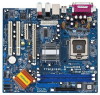
1.3 Motherboard Layout 1 2 3 PS2 Mouse 1 PS2_USB_PWR1 ATX12V1 21.8cm (8.6 in) 45 CPU_FAN1...1 PCI 2 USB2.0 IntIeClH6 CMOS Battery SPEAKER1 1 USB45 USB67 1 1 CLRCMOS1 1 USB45 PANEL1 PLED PWRBTN 1 HDLED RESET SATA1 SATA2 SATA3 SATA4 775i915PL-M PCI EXPRESS 24.4cm (9.6 in) 8 9 10 11 12 13 22 21 20 19 18 17 161514 1 PS2_USB_PWR1 Jumper 2...14 Fourth Serial ATA Connector (SATA4, black) 15 Third Serial ATA Connector (SATA3, black) 16 Secondary Serial ATA Connector (SATA2, blue) 17 Primary Serial ATA Connector (SATA1, blue) 18 System Panel Header (PANEL1) 19 USB 2.0 Header (USB67...
1.3 Motherboard Layout 1 2 3 PS2 Mouse 1 PS2_USB_PWR1 ATX12V1 21.8cm (8.6 in) 45 CPU_FAN1...1 PCI 2 USB2.0 IntIeClH6 CMOS Battery SPEAKER1 1 USB45 USB67 1 1 CLRCMOS1 1 USB45 PANEL1 PLED PWRBTN 1 HDLED RESET SATA1 SATA2 SATA3 SATA4 775i915PL-M PCI EXPRESS 24.4cm (9.6 in) 8 9 10 11 12 13 22 21 20 19 18 17 161514 1 PS2_USB_PWR1 Jumper 2...14 Fourth Serial ATA Connector (SATA4, black) 15 Third Serial ATA Connector (SATA3, black) 16 Secondary Serial ATA Connector (SATA2, blue) 17 Primary Serial ATA Connector (SATA1, blue) 18 System Panel Header (PANEL1) 19 USB 2.0 Header (USB67...

User Manual
Page 15
PCIE2 (PCIE x4 slot) is used for PCI Express cards, such as GigaLAN card, SATA2 card, etc. Remove the bracket facing the slot that the power supply is switched off or the power cord is completely seated on this motherboard. Keep the screws for the card before you intend to use . Step 3. PCIE...
PCIE2 (PCIE x4 slot) is used for PCI Express cards, such as GigaLAN card, SATA2 card, etc. Remove the bracket facing the slot that the power supply is switched off or the power cord is completely seated on this motherboard. Keep the screws for the card before you intend to use . Step 3. PCIE...

User Manual
Page 17
... the headers and connectors will cause permanent damage of the motherboard! Serial ATA Connectors (SATA1: see p.8 No. 17) (SATA2: see p.8 No. 16) (SATA3: see p.8 No. 15) (SATA4: see p.8 No. 11) PIN1 IDE1 connect the blue end connect the black end to the motherboard to the IDE devices 80-conductor ATA 66/100 cable...
... the headers and connectors will cause permanent damage of the motherboard! Serial ATA Connectors (SATA1: see p.8 No. 17) (SATA2: see p.8 No. 16) (SATA3: see p.8 No. 15) (SATA4: see p.8 No. 11) PIN1 IDE1 connect the blue end connect the black end to the motherboard to the IDE devices 80-conductor ATA 66/100 cable...

