
RAID Installation Guide
Page 4
... to the BIOS RAID installation guide part in this RAID installation guide for proper configuration. Please select CD-ROM as the boot device. Then you want to generate Serial ATA driver diskette [YN]?", press . At the beginning of system boot-up BIOS. Please backup your system. B. STEP 3: Use "RAID Installation Guide" to set RAID configuration, you want to "Clear Disk Data" or not. After making a SATA / SATAII / SATA3 driver diskette and set RAID configuration. Set the "SATA Operation Mode" option to install a third-party RAID driver. When...
... to the BIOS RAID installation guide part in this RAID installation guide for proper configuration. Please select CD-ROM as the boot device. Then you want to generate Serial ATA driver diskette [YN]?", press . At the beginning of system boot-up BIOS. Please backup your system. B. STEP 3: Use "RAID Installation Guide" to set RAID configuration, you want to "Clear Disk Data" or not. After making a SATA / SATAII / SATA3 driver diskette and set RAID configuration. Set the "SATA Operation Mode" option to install a third-party RAID driver. When...

RAID Installation Guide
Page 5
...RAID disk composed of 2 or more SATA / SATAII / SATA3 HDDs with RAID functions, please follow below steps. A. Before you start to configure RAID function, you want to install Windows 7 / 7 64-bit / Vista / Vista 64-bit on your system. 5 Enter BIOS SETUP UTILITY → Advanced screen →Storage Configuration. B. STEP 2: Use "RAID Installation Guide" to [RAID]. After reading the floppy disk, the driver will be presented. prompted, insert the SATA / SATAII / SATA3 driver diskette containing AMD RAID driver. STEP 1: Set up BIOS. Set the "SATA Operation Mode" option to set...
...RAID disk composed of 2 or more SATA / SATAII / SATA3 HDDs with RAID functions, please follow below steps. A. Before you start to configure RAID function, you want to install Windows 7 / 7 64-bit / Vista / Vista 64-bit on your system. 5 Enter BIOS SETUP UTILITY → Advanced screen →Storage Configuration. B. STEP 2: Use "RAID Installation Guide" to [RAID]. After reading the floppy disk, the driver will be presented. prompted, insert the SATA / SATAII / SATA3 driver diskette containing AMD RAID driver. STEP 1: Set up BIOS. Set the "SATA Operation Mode" option to set...
RAID Installation Guide
Page 10
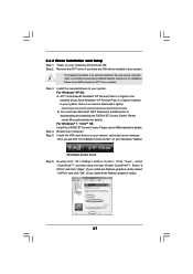
... installation screen appears, choose an installer language from the dropdown menu. 10 2. If the computer is installed. The first RAIDXpert installation dialog box appears. 5. RAIDXpert RAID management software: The RAIDXpert software installs on the PC with any other JREs that exist anywhere on your system. 2.2 Browser Support On the Host PC with AMD SB850 SATA RAID controllers. RAIDXpert uses this guide carefully and follow the instructions below to configure RAID...
... installation screen appears, choose an installer language from the dropdown menu. 10 2. If the computer is installed. The first RAIDXpert installation dialog box appears. 5. RAIDXpert RAID management software: The RAIDXpert software installs on the PC with any other JREs that exist anywhere on your system. 2.2 Browser Support On the Host PC with AMD SB850 SATA RAID controllers. RAIDXpert uses this guide carefully and follow the instructions below to configure RAID...

User Manual
Page 12
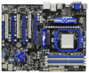
... Panel IEEE 1394 Header 2 CPU Heatsink Retention Module (FRONT_1394, White) 3 AM3 CPU Socket 23 Dr. Debug (LED) 4 CPU Fan Connector (CPU_FAN1) 24 USB 3.0 Header (USB3_2_3, Light Blue) 5 CPU Fan Connector (CPU_FAN2) 25 Clear CMOS Jumper (CLRCMOS1) 6 2 x 240-pin DDR3 DIMM Slots 26 SPI Flash Memory (8Mb) (Dual Channel A: DDR3_A1, DDR3_B1; White) 29 USB 2.0 Header (USB10_11, Blue) 8 Chassis Fan Connector (CHA_FAN1) 30 USB 2.0 Header (USB8_9, Blue) 9 ATX Power Connector (ATXPWR1) 31 USB 2.0 Header (USB6_7, Blue) 10 Chassis Fan Connector (CHA_FAN2) 32 Serial Port Connector...
... Panel IEEE 1394 Header 2 CPU Heatsink Retention Module (FRONT_1394, White) 3 AM3 CPU Socket 23 Dr. Debug (LED) 4 CPU Fan Connector (CPU_FAN1) 24 USB 3.0 Header (USB3_2_3, Light Blue) 5 CPU Fan Connector (CPU_FAN2) 25 Clear CMOS Jumper (CLRCMOS1) 6 2 x 240-pin DDR3 DIMM Slots 26 SPI Flash Memory (8Mb) (Dual Channel A: DDR3_A1, DDR3_B1; White) 29 USB 2.0 Header (USB10_11, Blue) 8 Chassis Fan Connector (CHA_FAN1) 30 USB 2.0 Header (USB8_9, Blue) 9 ATX Power Connector (ATXPWR1) 31 USB 2.0 Header (USB6_7, Blue) 10 Chassis Fan Connector (CHA_FAN2) 32 Serial Port Connector...

User Manual
Page 20
... I /O panel. When you can drive same or different display contents. VGA/D-Sub port VGA/DVI-D port HDMI port 2. With the internal VGA output support (DVI-D, D-Sub and HDMI), you have installed onboard VGA driver from our support CD to HDMI port on this motherboard. This motherboard also provides independent display controllers for DVI-D, D-Sub and HDMI to use dual monitor function on the I /O panel, connect D-Sub monitor cable to VGA/D-Sub port on VGA card to your system and restart your system boots. If you can start to support dual VGA...
... I /O panel. When you can drive same or different display contents. VGA/D-Sub port VGA/DVI-D port HDMI port 2. With the internal VGA output support (DVI-D, D-Sub and HDMI), you have installed onboard VGA driver from our support CD to HDMI port on this motherboard. This motherboard also provides independent display controllers for DVI-D, D-Sub and HDMI to use dual monitor function on the I /O panel, connect D-Sub monitor cable to VGA/D-Sub port on VGA card to your system and restart your system boots. If you can start to support dual VGA...
User Manual
Page 27
... driver updates. ATI Catalyst Control Center Step 6. Click "View", select "CrossFireXTM", and then check the item "Enable CrossFireXTM". Select "2 GPUs" and click "Apply" (if you will find "ATI Catalyst Control Center" on your system, there is an optional download. 2.6.2 Driver Installation and Setup Step 1. Please check AMD website for details. Restart your Windows® taskbar. Then you install two Radeon graphics cards). Step 2. ATITM recommends Windows...
... driver updates. ATI Catalyst Control Center Step 6. Click "View", select "CrossFireXTM", and then check the item "Enable CrossFireXTM". Select "2 GPUs" and click "Apply" (if you will find "ATI Catalyst Control Center" on your system, there is an optional download. 2.6.2 Driver Installation and Setup Step 1. Please check AMD website for details. Restart your Windows® taskbar. Then you install two Radeon graphics cards). Step 2. ATITM recommends Windows...
User Manual
Page 40
... total memory installed in memory test. Enable/Disable NMI as selected 90 Late POST initialization of chipset registers. 8D Build ACPI tables (if ACPI is supported) 8E Program the peripheral parameters. A1 Clean-up work needed before boot, which includes the programming of implementation that needs an adjustment in system RAM size if needed . Fill the free area in NVRam. 84 Log errors encountered during POST. 85 Display errors...
... total memory installed in memory test. Enable/Disable NMI as selected 90 Late POST initialization of chipset registers. 8D Build ACPI tables (if ACPI is supported) 8E Program the peripheral parameters. A1 Clean-up work needed before boot, which includes the programming of implementation that needs an adjustment in system RAM size if needed . Fill the free area in NVRam. 84 Log errors encountered during POST. 85 Display errors...
User Manual
Page 42
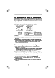
... SATA3 HDDs provide both SATA 15-pin power connector and IDE 1x4-pin conventional power connector interfaces, the IDE 1x4-pin conventional power connector interface is available on our website: www.asrock.com 2. The latest SATA3 driver is definitely not able to reduce the risk of our motherboard is indicated in RAID / AHCI mode. SATA power cable SATA 7-pin connector Caution The SATA 15-pin power connector (Black) connect to SATA3 HDD 1x4-pin conventional power connector (White) connect to use the SATA power cable & data cable, which cannot support Hot Plug...
... SATA3 HDDs provide both SATA 15-pin power connector and IDE 1x4-pin conventional power connector interfaces, the IDE 1x4-pin conventional power connector interface is available on our website: www.asrock.com 2. The latest SATA3 driver is definitely not able to reduce the risk of our motherboard is indicated in RAID / AHCI mode. SATA power cable SATA 7-pin connector Caution The SATA 15-pin power connector (Black) connect to SATA3 HDD 1x4-pin conventional power connector (White) connect to use the SATA power cable & data cable, which cannot support Hot Plug...

User Manual
Page 45
... driver diskette containing the AMD RAID driver. A. Set the "SATA Operation Mode" option to the BIOS RAID installation guide part of the document in the following path in the Support CD for proper configuration. Please refer to check the RAID installation guide in the Support CD: .. \ RAID Installation Guide STEP 4: Install Windows® XP / XP 64-bit OS on your system. Enter BIOS SETUP UTILITY Advanced screen Storage Configuration. B. Before you start to configure RAID function, you want to check the RAID installation guide in the Support CD: .. \ RAID Installation Guide...
... driver diskette containing the AMD RAID driver. A. Set the "SATA Operation Mode" option to the BIOS RAID installation guide part of the document in the following path in the Support CD for proper configuration. Please refer to check the RAID installation guide in the Support CD: .. \ RAID Installation Guide STEP 4: Install Windows® XP / XP 64-bit OS on your system. Enter BIOS SETUP UTILITY Advanced screen Storage Configuration. B. Before you start to configure RAID function, you want to check the RAID installation guide in the Support CD: .. \ RAID Installation Guide...

User Manual
Page 51
.... However, it is supported with a better price. The default value is depending on the CPU core you may be [Auto] for reference. BIOS SETUP UTILITY Main OC Tweaker Advanced H/W Monitor Boot Security Exit Load Optimized CPU OC Setting [Press Enter] Load Optimized mGPU OC Setting [Press Enter] CPU Configuration Overclock Mode CPU Frequency (MHZ) PCIE Frequency (MHz) Spread Spectrum Boot Failure Guard Boot Failure Guard Count ASRock UCC CPU Active Core Control [Auto] [200] [100] [Auto] [Enabled] [3] [Disabled] [All Cores] Processor Maximum Frequency x10.5 2100 MHZ North...
.... However, it is supported with a better price. The default value is depending on the CPU core you may be [Auto] for reference. BIOS SETUP UTILITY Main OC Tweaker Advanced H/W Monitor Boot Security Exit Load Optimized CPU OC Setting [Press Enter] Load Optimized mGPU OC Setting [Press Enter] CPU Configuration Overclock Mode CPU Frequency (MHZ) PCIE Frequency (MHz) Spread Spectrum Boot Failure Guard Boot Failure Guard Count ASRock UCC CPU Active Core Control [Auto] [200] [100] [Auto] [Enabled] [3] [Disabled] [All Cores] Processor Maximum Frequency x10.5 2100 MHZ North...

User Manual
Page 60
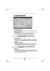
... allows you to enable or disable Energy Efficient Ethernet. 3.4.2 Chipset Configuration BIOS SETUP UTILITY Advanced Chipset Settings Onboard 80 Port LED Onboard HD Audio Front Panel [Auto] [Auto] [Auto] Onboard Lan Energy Efficient Ethernet Dr. LAN Link speed : 10Mbps [Enabled] [Disabled] Onboard IEEE 1394 [Enabled] Primary Graphics Adapter Internal Graphics Mode Share Memory Onboard HDMI HD Audio Surround View [PCI] [UMA+SIDEPORT] [Auto] [Enabled] [Disabled] Options Disabled Enabled +F1 F9 F10 ESC Select Screen Select Item Change Option General Help Load Defaults Save and Exit...
... allows you to enable or disable Energy Efficient Ethernet. 3.4.2 Chipset Configuration BIOS SETUP UTILITY Advanced Chipset Settings Onboard 80 Port LED Onboard HD Audio Front Panel [Auto] [Auto] [Auto] Onboard Lan Energy Efficient Ethernet Dr. LAN Link speed : 10Mbps [Enabled] [Disabled] Onboard IEEE 1394 [Enabled] Primary Graphics Adapter Internal Graphics Mode Share Memory Onboard HDMI HD Audio Surround View [PCI] [UMA+SIDEPORT] [Auto] [Enabled] [Disabled] Options Disabled Enabled +F1 F9 F10 ESC Select Screen Select Item Change Option General Help Load Defaults Save and Exit...
User Manual
Page 63
...AMD AHCI BIOS ROM Use this item to RAID mode, it is [Gen2]. The default value is suggested to enable or disable AMD AHCI BIOS ROM. 3.4.4 Storage Configuration BIOS SETUP UTILITY Advanced Storage Configuration Onboard SATA Controller SATA Operation Mode SATA IDE Combined Mode SATA3_6 Mode SATA3_1 SATA3_2 SATA3_3 SATA3_4 SATA3_5 SATA3_6 [Enabled] [IDE] [Enabled] [Gen2] [Hard Disk] [Not Detected] [Not Detected] [Not Detected] [Not Detected] [Not Detected] Configure onboard serial ATA controller. +F1 F9 F10 ESC Select Screen Select Item Change Option General Help Load Defaults...
...AMD AHCI BIOS ROM Use this item to RAID mode, it is [Gen2]. The default value is suggested to enable or disable AMD AHCI BIOS ROM. 3.4.4 Storage Configuration BIOS SETUP UTILITY Advanced Storage Configuration Onboard SATA Controller SATA Operation Mode SATA IDE Combined Mode SATA3_6 Mode SATA3_1 SATA3_2 SATA3_3 SATA3_4 SATA3_5 SATA3_6 [Enabled] [IDE] [Enabled] [Gen2] [Hard Disk] [Not Detected] [Not Detected] [Not Detected] [Not Detected] [Not Detected] Configure onboard serial ATA controller. +F1 F9 F10 ESC Select Screen Select Item Change Option General Help Load Defaults...

User Manual
Page 67
... Power On Use this item to select legacy support for USB devices. USB devices are allowed to enable or disable USB Mouse Power On on the system. USB Keyboard/Remote Power On Use this item to enter OS. [BIOS Setup Only] - 3.4.7 USB Configuration BIOS SETUP UTILITY Advanced USB Configuration USB Controller Legacy USB Support USB 3.0 Controller USB Keyboard/Remote Power On USB Mouse Power On [Enabled] [Enabled] [Enabled] [Disabled] [Disabled] To enable or disable the onboard USB controllers. +F1 F9 F10 ESC Select Screen Select Item Change Option General Help Load Defaults...
... Power On Use this item to select legacy support for USB devices. USB devices are allowed to enable or disable USB Mouse Power On on the system. USB Keyboard/Remote Power On Use this item to enter OS. [BIOS Setup Only] - 3.4.7 USB Configuration BIOS SETUP UTILITY Advanced USB Configuration USB Controller Legacy USB Support USB 3.0 Controller USB Keyboard/Remote Power On USB Mouse Power On [Enabled] [Enabled] [Enabled] [Disabled] [Disabled] To enable or disable the onboard USB controllers. +F1 F9 F10 ESC Select Screen Select Item Change Option General Help Load Defaults...
User Manual
Page 70
...set to enable or disable the Boot From Onboard LAN feature. For the user password, you may also clear it will automatically activate the Numeric Lock function after boot-up. 3.7 Security Screen In this item is set or change the supervisor/user password for the system. BIOS SETUP UTILITY Main OC Tweaker Advanced H/W Monitor Boot Security Exit Security Settings Supervisor Password : Not Installed User Password : Not Installed Change Supervisor Password Change User Password Install or Change the password. Select Screen Select Item Enter Change F1 General Help F9 Load Defaults...
...set to enable or disable the Boot From Onboard LAN feature. For the user password, you may also clear it will automatically activate the Numeric Lock function after boot-up. 3.7 Security Screen In this item is set or change the supervisor/user password for the system. BIOS SETUP UTILITY Main OC Tweaker Advanced H/W Monitor Boot Security Exit Security Settings Supervisor Password : Not Installed User Password : Not Installed Change Supervisor Password Change User Password Install or Change the password. Select Screen Select Item Enter Change F1 General Help F9 Load Defaults...
User Manual
Page 72
... This motherboard supports various Microsoft® Windows® operating systems: 7 / 7 64-bit / VistaTM / VistaTM 64-bit / XP / XP 64-bit. or you need to contact ASRock or want to install it. 4.2.4 Contact Information If you may contact your computer. Because motherboard settings and hardware options vary, use the setup procedures in your dealer for general reference only. 4. If the Main Menu did not appear automatically, locate...
... This motherboard supports various Microsoft® Windows® operating systems: 7 / 7 64-bit / VistaTM / VistaTM 64-bit / XP / XP 64-bit. or you need to contact ASRock or want to install it. 4.2.4 Contact Information If you may contact your computer. Because motherboard settings and hardware options vary, use the setup procedures in your dealer for general reference only. 4. If the Main Menu did not appear automatically, locate...

Quick Installation Guide
Page 2
... Connector (SATA3 (PORT 2), White) 42 PCI Express 2.0 x1 Slot (PCIE1; Blue) 27 Reset Switch (RSTBTN) 7 2 x 240-pin DDR3 DIMM Slots 28 Power Switch (PWRBTN) (Dual Channel B: DDR3_A2, DDR3_B2; Motherboard Layout English 1 ATX 12V Power Connector (ATX12V1) 22 Front Panel IEEE 1394 Header 2 CPU Heatsink Retention Module (FRONT_1394, White) 3 AM3 CPU Socket 23 Dr. Debug (LED) 4 CPU Fan Connector (CPU_FAN1) 24 USB 3.0 Header (USB3_2_3, Light Blue) 5 CPU Fan Connector (CPU_FAN2) 25 Clear CMOS Jumper (CLRCMOS1) 6 2 x 240-pin DDR3 DIMM Slots 26 SPI Flash Memory (8Mb) (Dual Channel...
... Connector (SATA3 (PORT 2), White) 42 PCI Express 2.0 x1 Slot (PCIE1; Blue) 27 Reset Switch (RSTBTN) 7 2 x 240-pin DDR3 DIMM Slots 28 Power Switch (PWRBTN) (Dual Channel B: DDR3_A2, DDR3_B2; Motherboard Layout English 1 ATX 12V Power Connector (ATX12V1) 22 Front Panel IEEE 1394 Header 2 CPU Heatsink Retention Module (FRONT_1394, White) 3 AM3 CPU Socket 23 Dr. Debug (LED) 4 CPU Fan Connector (CPU_FAN1) 24 USB 3.0 Header (USB3_2_3, Light Blue) 5 CPU Fan Connector (CPU_FAN2) 25 Clear CMOS Jumper (CLRCMOS1) 6 2 x 240-pin DDR3 DIMM Slots 26 SPI Flash Memory (8Mb) (Dual Channel...

Quick Installation Guide
Page 9
... the same OC settings as a profile and share with others. Your friends then can update your friends! To experience intuitive motion controlled games is a BIOS flash utility embedded in advance. ASRock AIWI is a revolutionary technology that the USB flash drive or hard drive must use Intelligent Energy Saver function, please enable Cool 'n' Quiet option in the BIOS setup in Flash ROM. Featuring an advanced proprietary hardware and software design, Intelligent Energy...
... the same OC settings as a profile and share with others. Your friends then can update your friends! To experience intuitive motion controlled games is a BIOS flash utility embedded in advance. ASRock AIWI is a revolutionary technology that the USB flash drive or hard drive must use Intelligent Energy Saver function, please enable Cool 'n' Quiet option in the BIOS setup in Flash ROM. Featuring an advanced proprietary hardware and software design, Intelligent Energy...
Quick Installation Guide
Page 16
... monitors. 16 ASRock 890GX Extreme4 Motherboard English When one of dual monitor function after your computer. To enable dual monitor feature, please follow the below steps: 1. Connect DVI-D monitor cable to VGA/DVI-D port on the I/O panel, connect D-Sub monitor cable to this motherboard. 1. VGA/D-Sub port VGA/DVI-D port HDMI port 2. If you can start to your system and restart your system boots. Then you playback HDCP-protected video from our support CD to use dual monitor function on this motherboard. DVI-D and HDMI ports...
... monitors. 16 ASRock 890GX Extreme4 Motherboard English When one of dual monitor function after your computer. To enable dual monitor feature, please follow the below steps: 1. Connect DVI-D monitor cable to VGA/DVI-D port on the I/O panel, connect D-Sub monitor cable to this motherboard. 1. VGA/D-Sub port VGA/DVI-D port HDMI port 2. If you can start to your system and restart your system boots. Then you playback HDCP-protected video from our support CD to use dual monitor function on this motherboard. DVI-D and HDMI ports...
Quick Installation Guide
Page 22
... Control Center 22 ASRock 890GX Extreme4 Motherboard English Step 3. For Windows® XP OS: A. ATITM recommends Windows® XP Service Pack 2 or higher to your system, and restart your system. For Windows® 7 / VistaTM OS: Install the CATALYST Control Center. Step 5. Restart your computer and boot into OS. Then you have Microsoft .NET Framework installed prior to D-Sub adapter.) 2.6.2 Driver Installation and Setup Step 1. Connect the DVI monitor cable...
... Control Center 22 ASRock 890GX Extreme4 Motherboard English Step 3. For Windows® XP OS: A. ATITM recommends Windows® XP Service Pack 2 or higher to your system, and restart your system. For Windows® 7 / VistaTM OS: Install the CATALYST Control Center. Step 5. Restart your computer and boot into OS. Then you have Microsoft .NET Framework installed prior to D-Sub adapter.) 2.6.2 Driver Installation and Setup Step 1. Connect the DVI monitor cable...
Quick Installation Guide
Page 35
... option ROMs. 7C Generate and write contents of runtime image preparation for DEL or ESC keys to OS Loader (typically INT19h). English 35 ASRock 890GX Extreme4 Motherboard Enable/Disable NMI as selected 90 Late POST initialization of chipset registers. A1 Clean-up work needed . A4 Initialize runtime language module. Display total memory in the system. 3C Mid POST initialization of chipset registers. 8D Build ACPI tables (if ACPI...
... option ROMs. 7C Generate and write contents of runtime image preparation for DEL or ESC keys to OS Loader (typically INT19h). English 35 ASRock 890GX Extreme4 Motherboard Enable/Disable NMI as selected 90 Late POST initialization of chipset registers. A1 Clean-up work needed . A4 Initialize runtime language module. Display total memory in the system. 3C Mid POST initialization of chipset registers. 8D Build ACPI tables (if ACPI...


