
User Manual
Page 3
... 5 1.2 Specifications 6 1.3 Motherboard Layout 10 1.4 I/O Panel 11 2 Installation 12 2.1 Screw Holes 12 2.2 Pre-installation Precautions 12 2.3 Installation of Memory Modules (DIMM 13 2.4 Expansion Slot (PCI Slot 14 2.5 Jumpers Setup 15 2.6 Onboard Headers and Connectors 16 2.7 SATAII Hard Disk Setup Guide 19 2.8 Serial ATA (SATA) / Serial ATAII (SATAII) Hard Disks Installation 20 2.9 Hot Plug Function for SATA / SATAII HDDs 20 2.10 SATA / SATAII HDD Hot Plug Feature and Operation Guide 21 2.11 Driver Installation Guide 23 2.12 Installing Windows® 7 / 7 64-bit / VistaTM...
... 5 1.2 Specifications 6 1.3 Motherboard Layout 10 1.4 I/O Panel 11 2 Installation 12 2.1 Screw Holes 12 2.2 Pre-installation Precautions 12 2.3 Installation of Memory Modules (DIMM 13 2.4 Expansion Slot (PCI Slot 14 2.5 Jumpers Setup 15 2.6 Onboard Headers and Connectors 16 2.7 SATAII Hard Disk Setup Guide 19 2.8 Serial ATA (SATA) / Serial ATAII (SATAII) Hard Disks Installation 20 2.9 Hot Plug Function for SATA / SATAII HDDs 20 2.10 SATA / SATAII HDD Hot Plug Feature and Operation Guide 21 2.11 Driver Installation Guide 23 2.12 Installing Windows® 7 / 7 64-bit / VistaTM...

User Manual
Page 7
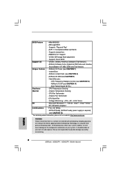
...AMI Legal BIOS - Supports "Plug and Play" - Boot Failure Guard (B.F.G.) Hardware - Chassis Fan Tachometer - FCC, CE, WHQL - Drivers, Utilities, AntiVirus Software (Trial Version), ASRock Software Suite (CyberLink DVD Suite and Creative Sound Blaster X-Fi MB) (OEM and Trial Version) Unique Feature - Chassis Temperature Sensing - ErP/EuP Ready (ErP/EuP ready power supply is a certain risk involved with overclocking, including adjusting the setting in the BIOS, applying Untied Overclocking Technology, or using the thirdparty overclocking tools. Voltage Monitoring: +12V, +5V...
...AMI Legal BIOS - Supports "Plug and Play" - Boot Failure Guard (B.F.G.) Hardware - Chassis Fan Tachometer - FCC, CE, WHQL - Drivers, Utilities, AntiVirus Software (Trial Version), ASRock Software Suite (CyberLink DVD Suite and Creative Sound Blaster X-Fi MB) (OEM and Trial Version) Unique Feature - Chassis Temperature Sensing - ErP/EuP Ready (ErP/EuP ready power supply is a certain risk involved with overclocking, including adjusting the setting in the BIOS, applying Untied Overclocking Technology, or using the thirdparty overclocking tools. Voltage Monitoring: +12V, +5V...

User Manual
Page 8
... update your friends! tied Overclocking Technology" on the same motherboard. 10. Due to access ASRock Instant Flash. You can press key during the POST or press key to BIOS setup menu to the chipset limitation, the actual memory size may cause the instability of the system or damage the CPU. 8 Power Management for the latest information. 5. ASRock Instant Flash is subject to SATAII connector directly. 6. With this utility, you can also connect SATA hard disk to change...
... update your friends! tied Overclocking Technology" on the same motherboard. 10. Due to access ASRock Instant Flash. You can press key during the POST or press key to BIOS setup menu to the chipset limitation, the actual memory size may cause the instability of the system or damage the CPU. 8 Power Management for the latest information. 5. ASRock Instant Flash is subject to SATAII connector directly. 6. With this utility, you can also connect SATA hard disk to change...

User Manual
Page 10
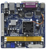
... RESET PANEL 1 SPEAKER1 1 13 7 8 9 10 11 12 1 PS2_USB_PWR1 Jumper 10 USB 2.0 Header (USB6_7, Blue) 2 CPU Fan Connector (CPU_FAN1) 11 USB 2.0 Header (USB4_5, Blue) 3 CPU Fan 12 System Panel Header (PANEL1, White) 4 CPU Heatsink 13 Chassis Speaker Header (SPEAKER 1, White) 5 2 x 240-pin DDR2 DIMM Slots 14 BIOS SPI Chip (Dual Channel: DDRII_1, DDRII_2; Blue) 18 South Bridge Controller 10 Blue) (HD_AUDIO1, White) 9 Primary SATAII Connector (SATAII_1; Yellow) 15 PCI Slot (PCI1) 6 ATX Power Connector (ATXPWR1) 16 Internal Audio Connector: CD1 (Black) 7 Chassis Fan...
... RESET PANEL 1 SPEAKER1 1 13 7 8 9 10 11 12 1 PS2_USB_PWR1 Jumper 10 USB 2.0 Header (USB6_7, Blue) 2 CPU Fan Connector (CPU_FAN1) 11 USB 2.0 Header (USB4_5, Blue) 3 CPU Fan 12 System Panel Header (PANEL1, White) 4 CPU Heatsink 13 Chassis Speaker Header (SPEAKER 1, White) 5 2 x 240-pin DDR2 DIMM Slots 14 BIOS SPI Chip (Dual Channel: DDRII_1, DDRII_2; Blue) 18 South Bridge Controller 10 Blue) (HD_AUDIO1, White) 9 Primary SATAII Connector (SATAII_1; Yellow) 15 PCI Slot (PCI1) 6 ATX Power Connector (ATXPWR1) 16 Internal Audio Connector: CD1 (Black) 7 Chassis Fan...

User Manual
Page 16
...-ROM, DVD-ROM, TV tuner card, or MPEG card. Serial ATA (SATA) Data Cable (Optional) USB 2.0 Headers (9-pin USB6_7) (see p.10 No. 10) (9-pin USB4_5) (see p.10 No. 11) Internal Audio Connector (4-pin CD1) (CD1: see p.10 No. 17) 16 GND PRESENCE# MIC_RET OUT_RET 1 OUT2_L J_SENSE OUT2_R MIC2_R MIC2_L This is an interface for internal storage devices. Besides four default USB 2.0 ports on the I/O panel, there are NOT jumpers. 2.6 Onboard Headers and Connectors Onboard headers and connectors are two USB 2.0 headers on this motherboard...
...-ROM, DVD-ROM, TV tuner card, or MPEG card. Serial ATA (SATA) Data Cable (Optional) USB 2.0 Headers (9-pin USB6_7) (see p.10 No. 10) (9-pin USB4_5) (see p.10 No. 11) Internal Audio Connector (4-pin CD1) (CD1: see p.10 No. 17) 16 GND PRESENCE# MIC_RET OUT_RET 1 OUT2_L J_SENSE OUT2_R MIC2_R MIC2_L This is an interface for internal storage devices. Besides four default USB 2.0 ports on the I/O panel, there are NOT jumpers. 2.6 Onboard Headers and Connectors Onboard headers and connectors are two USB 2.0 headers on this motherboard...
User Manual
Page 17
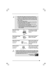
... chassis manual to [Enabled]. System Panel Header (9-pin PANEL1) (see p.10 No. 12) Chassis Speaker Header (4-pin SPEAKER 1) (see p.10 No. 13) Chassis Fan Connector (4-pin CHA_FAN1) (see p.10 No. 2) 4 3 2 1 GND +12V CPU_FAN_SPEED FAN_SPEED_CONTROL Please connect a CPU fan cable to this motherboard, please connect it to Pin 1-3. D. Set the Front Panel Control option from [Auto] to install your system. 2. B. Enter BIOS Setup Utility. Though this motherboard provides 4-Pin CPU fan (Quiet Fan) support, the 3-Pin CPU fan still can work successfully even without the fan speed control...
... chassis manual to [Enabled]. System Panel Header (9-pin PANEL1) (see p.10 No. 12) Chassis Speaker Header (4-pin SPEAKER 1) (see p.10 No. 13) Chassis Fan Connector (4-pin CHA_FAN1) (see p.10 No. 2) 4 3 2 1 GND +12V CPU_FAN_SPEED FAN_SPEED_CONTROL Please connect a CPU fan cable to this motherboard, please connect it to Pin 1-3. D. Set the Front Panel Control option from [Auto] to install your system. 2. B. Enter BIOS Setup Utility. Though this motherboard provides 4-Pin CPU fan (Quiet Fan) support, the 3-Pin CPU fan still can work successfully even without the fan speed control...
User Manual
Page 19
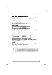
... pin 3 and pin 4. 2.7 SATAII Hard Disk Setup Guide Before installing SATAII hard disk to your computer, please carefully read below instruction with the best performance. Some default setting of different vendors, the jumper pin setting methods may not be the same. For different SATAII hard disk products of SATAII hard disks may not be at SATAII mode. otherwise, your reference. HITACHI Please use the Feature Tool, a DOS-bootable tool, for the updates...
... pin 3 and pin 4. 2.7 SATAII Hard Disk Setup Guide Before installing SATAII hard disk to your computer, please carefully read below instruction with the best performance. Some default setting of different vendors, the jumper pin setting methods may not be the same. For different SATAII hard disk products of SATAII hard disks may not be at SATAII mode. otherwise, your reference. HITACHI Please use the Feature Tool, a DOS-bootable tool, for the updates...
User Manual
Page 23
.... Enter BIOS SETUP UTILITY Advanced screen Storage Configuration. Therefore, the drivers you install can work properly. 2.12 Installing Windows® 7 / 7 64-bit / VistaTM / VistaTM 64-bit / XP / XP 64-bit Without RAID Functions If you want to install Windows® XP / XP 64-bit OS on your system can be auto-detected and listed on your optical drive first. AHCI mode is not supported under Windows® XP / XP 64-bit OS. Then, the drivers compatible to your SATA / SATAII HDDs...
.... Enter BIOS SETUP UTILITY Advanced screen Storage Configuration. Therefore, the drivers you install can work properly. 2.12 Installing Windows® 7 / 7 64-bit / VistaTM / VistaTM 64-bit / XP / XP 64-bit Without RAID Functions If you want to install Windows® XP / XP 64-bit OS on your system can be auto-detected and listed on your optical drive first. AHCI mode is not supported under Windows® XP / XP 64-bit OS. Then, the drivers compatible to your SATA / SATAII HDDs...

User Manual
Page 33
3.4.1 CPU Configuration BIOS SETUP UTILITY Advanced CPU Configuration Ratio Actual Value CPU Thermal Throttling No-Execute Memory Protection Hyper Threading Technology 10 [Enabled] [Disabled] [Enabled] Enter to the IA-32 Intel Architecture. An IA-32 processor with an Intel Pentium® 4 processor that supports Hyper-Threading technology and an operating system that includes optimization for this technology, such as Microsoft® Windows® XP. No-Excute Memory Protection No-Execution (NX) Memory Protection...
3.4.1 CPU Configuration BIOS SETUP UTILITY Advanced CPU Configuration Ratio Actual Value CPU Thermal Throttling No-Execute Memory Protection Hyper Threading Technology 10 [Enabled] [Disabled] [Enabled] Enter to the IA-32 Intel Architecture. An IA-32 processor with an Intel Pentium® 4 processor that supports Hyper-Threading technology and an operating system that includes optimization for this technology, such as Microsoft® Windows® XP. No-Excute Memory Protection No-Execution (NX) Memory Protection...

User Manual
Page 34
... BIOS SETUP UTILITY Advanced Chipset Settings Primary Graphics Adapter Internal Graphics Mode Select DVMT Mode Select DVMT/FIXED Memory Onboard HD Audio Front Panel OnBoard Lan [PCI] [Auto] [DVMT Mode] [Maximum DVMT] [Auto] [Enabled] [Enabled] Select the type of primary VGA in this option to 64MB of memory and up to adjust DVMT mode. Configuration options: [Onboard] and [PCI]. DVMT (Dynamic Video Memory Technology) is an architecture that at least 64MB of any add-on VGA card. Internal Graphics Mode Select If you select [Auto], the onboard VGA will be automatically disabled...
... BIOS SETUP UTILITY Advanced Chipset Settings Primary Graphics Adapter Internal Graphics Mode Select DVMT Mode Select DVMT/FIXED Memory Onboard HD Audio Front Panel OnBoard Lan [PCI] [Auto] [DVMT Mode] [Maximum DVMT] [Auto] [Enabled] [Enabled] Select the type of primary VGA in this option to 64MB of memory and up to adjust DVMT mode. Configuration options: [Onboard] and [PCI]. DVMT (Dynamic Video Memory Technology) is an architecture that at least 64MB of any add-on VGA card. Internal Graphics Mode Select If you select [Auto], the onboard VGA will be automatically disabled...

User Manual
Page 38
... IDE hard disk drives. Configuration options: [Disabled], [Auto], [Enabled]. 32-Bit Data Transfer Use this item is used for a hard disk > 512 MB under DOS and Windows; Make sure to set the PIO mode to select the LBA/Large mode for IDE ARMD (ATAPI Removable Media Device), such as FDISK, to disable the LBA/Large mode. for compatible IDE devices. If this item to enable or disable the S.M.A.R.T. (Self-Monitoring, Analysis, and Reporting Technology) feature. After selecting the hard disk information into BIOS, use a disk utility...
... IDE hard disk drives. Configuration options: [Disabled], [Auto], [Enabled]. 32-Bit Data Transfer Use this item is used for a hard disk > 512 MB under DOS and Windows; Make sure to set the PIO mode to select the LBA/Large mode for IDE ARMD (ATAPI Removable Media Device), such as FDISK, to disable the LBA/Large mode. for compatible IDE devices. If this item to enable or disable the S.M.A.R.T. (Self-Monitoring, Analysis, and Reporting Technology) feature. After selecting the hard disk information into BIOS, use a disk utility...

User Manual
Page 40
... [DMA3]. Configuration options: [IRQ5] and [IRQ7]. 40 ECP Mode DMA Channel Use this item to set the address for the onboard parallel port or disable it . Serial Port Address Use this item to set the IRQ for the onboard serial port or disable it . Parallel Port Mode Use this item to set the EPP version. Parallel Port IRQ Use this item to Enable or Disable Floppy Controller. +F1 F9 F10 ESC Select Screen Select Item Change Option General Help Load Defaults Save and...
... [DMA3]. Configuration options: [IRQ5] and [IRQ7]. 40 ECP Mode DMA Channel Use this item to set the address for the onboard parallel port or disable it . Serial Port Address Use this item to set the IRQ for the onboard serial port or disable it . Parallel Port Mode Use this item to set the EPP version. Parallel Port IRQ Use this item to Enable or Disable Floppy Controller. +F1 F9 F10 ESC Select Screen Select Item Change Option General Help Load Defaults Save and...

User Manual
Page 41
... value is recommended to select [Disabled] to select legacy support for legacy USB. [Auto] - USB devices are four configuration options: [Enabled], [Auto], [Disabled] and [BIOS Setup Only]. Legacy USB Support Use this item to use of these four options: [Enabled] - 3.4.7 USB Configuration BIOS SETUP UTILITY Advanced USB Configuration USB Controller USB 2.0 Support Legacy USB Support [Enabled] [Enabled] [Enabled] To enable or disable the onboard USB controllers. +F1 F9 F10 ESC Select Screen Select Item Change Option General Help Load Defaults Save and Exit Exit v02.54...
... value is recommended to select [Disabled] to select legacy support for legacy USB. [Auto] - USB devices are four configuration options: [Enabled], [Auto], [Disabled] and [BIOS Setup Only]. Legacy USB Support Use this item to use of these four options: [Enabled] - 3.4.7 USB Configuration BIOS SETUP UTILITY Advanced USB Configuration USB Controller USB 2.0 Support Legacy USB Support [Enabled] [Enabled] [Enabled] To enable or disable the onboard USB controllers. +F1 F9 F10 ESC Select Screen Select Item Change Option General Help Load Defaults Save and Exit Exit v02.54...
User Manual
Page 44
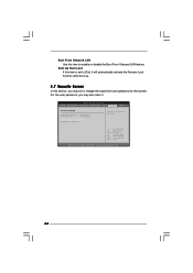
BIOS SETUP UTILITY Main OC Tweaker Advanced H/W Monitor Boot Security Exit Security Settings Supervisor Password : Not Installed User Password : Not Installed Change Supervisor Password Change User Password Install or Change the password. For the user password, you may also clear it. Boot Up Num-Lock If this item is set or change the supervisor/user password for the system. Boot From Onboard LAN Use this section, you may set to [On], it will automatically activate the Numeric Lock function after boot-up. 3.7 Security Screen In this...
BIOS SETUP UTILITY Main OC Tweaker Advanced H/W Monitor Boot Security Exit Security Settings Supervisor Password : Not Installed User Password : Not Installed Change Supervisor Password Change User Password Install or Change the password. For the user password, you may also clear it. Boot Up Num-Lock If this item is set or change the supervisor/user password for the system. Boot From Onboard LAN Use this section, you may set to [On], it will automatically activate the Numeric Lock function after boot-up. 3.7 Security Screen In this...
User Manual
Page 46
...-bit. Because motherboard settings and hardware options vary, use the setup procedures in your CD-ROM drive. The CD automatically displays the Main Menu if "AUTORUN" is enabled in this chapter for further information. 46 or you need to contact ASRock or want to know more information. 4.2 Support CD Information The Support CD that came with the motherboard contains necessary drivers and useful utilities that the motherboard supports. Please install the necessary drivers...
...-bit. Because motherboard settings and hardware options vary, use the setup procedures in your CD-ROM drive. The CD automatically displays the Main Menu if "AUTORUN" is enabled in this chapter for further information. 46 or you need to contact ASRock or want to know more information. 4.2 Support CD Information The Support CD that came with the motherboard contains necessary drivers and useful utilities that the motherboard supports. Please install the necessary drivers...
Quick Installation Guide
Page 6
...- Drivers, Utilities, AntiVirus Software (Trial Version), ASRock Software Suite (CyberLink DVD Suite and Creative Sound Blaster X-Fi MB) (OEM and Trial Version) Unique Feature - ASRock Instant Flash (see CAUTION 10) - CPU Temperature Sensing Monitor - FCC, CE, WHQL - Instant Boot - Hybrid Booster: - We are not responsible for possible damage caused by overclocking. Supports jumperfree - Supports Smart BIOS Support CD - CPU Frequency Stepless Control (see CAUTION 8) - ASRock U-COP (see CAUTION 9) - CPU Fan Tachometer - VCCM, SB Voltage Multi...
...- Drivers, Utilities, AntiVirus Software (Trial Version), ASRock Software Suite (CyberLink DVD Suite and Creative Sound Blaster X-Fi MB) (OEM and Trial Version) Unique Feature - ASRock Instant Flash (see CAUTION 10) - CPU Temperature Sensing Monitor - FCC, CE, WHQL - Instant Boot - Hybrid Booster: - We are not responsible for possible damage caused by overclocking. Supports jumperfree - Supports Smart BIOS Support CD - CPU Frequency Stepless Control (see CAUTION 8) - ASRock U-COP (see CAUTION 9) - CPU Fan Tachometer - VCCM, SB Voltage Multi...
Quick Installation Guide
Page 7
... the CPU. 7 ASRock AD525PV / AD425PV Motherboard English ASRock Instant Flash is a BIOS flash utility embedded in the support CD. 2. With OC DNA, you can only be noticed that the USB flash drive or hard drive must use FAT32/16/12 file system. 9. Please be shared and worked on the same motherboard. 10. Due to SATAII connector, please read "Untied Overclocking Technology" on page 19 of overclocking settings. Before installing SATAII hard disk to the chipset limitation, the actual memory size...
... the CPU. 7 ASRock AD525PV / AD425PV Motherboard English ASRock Instant Flash is a BIOS flash utility embedded in the support CD. 2. With OC DNA, you can only be noticed that the USB flash drive or hard drive must use FAT32/16/12 file system. 9. Please be shared and worked on the same motherboard. 10. Due to SATAII connector, please read "Untied Overclocking Technology" on page 19 of overclocking settings. Before installing SATAII hard disk to the chipset limitation, the actual memory size...
Quick Installation Guide
Page 14
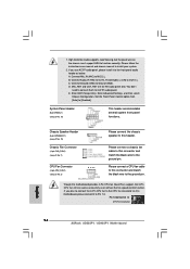
...AC'97 audio panel. Enter BIOS Setup Utility. System Panel Header (9-pin PANEL1) (see p.2 No. 2) 4 3 2 1 Please connect the chassis speaker to connect them for HD audio panel only. Though this header. Pin 1-3 Connected 3-Pin Fan Installation English 14 ASRock AD525PV / AD425PV Motherboard Connect Mic_IN (MIC) to [Enabled]. You don't need to this motherboard provides 4-Pin CPU fan (Quiet Fan) support, the 3-Pin CPU fan still can work successfully even without the fan speed control function. Set the Front Panel Control option from [Auto] to MIC2_L. Chassis Speaker Header (4-pin...
...AC'97 audio panel. Enter BIOS Setup Utility. System Panel Header (9-pin PANEL1) (see p.2 No. 2) 4 3 2 1 Please connect the chassis speaker to connect them for HD audio panel only. Though this header. Pin 1-3 Connected 3-Pin Fan Installation English 14 ASRock AD525PV / AD425PV Motherboard Connect Mic_IN (MIC) to [Enabled]. You don't need to this motherboard provides 4-Pin CPU fan (Quiet Fan) support, the 3-Pin CPU fan still can work successfully even without the fan speed control function. Set the Front Panel Control option from [Auto] to MIC2_L. Chassis Speaker Header (4-pin...
Quick Installation Guide
Page 17
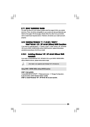
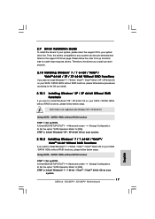
... steps. Enter BIOS SETUP UTILITY Advanced screen Storage Configuration. A. B. STEP 2: Install Windows® XP / XP 64-bit OS on your system. 2.10.2 Installing Windows® 7 / 7 64-bit / VistaTM / VistaTM 64-bit Without RAID Functions If you want to install Windows® 7 / 7 64-bit / VistaTM / VistaTM 64-bit OS on your system. 17 ASRock AD525PV / AD425PV Motherboard English Enter BIOS SETUP UTILITY Advanced screen Storage Configuration. STEP 2: Install Windows® 7 / 7 64-bit / VistaTM / VistaTM 64-bit OS on your SATA / SATAII HDDs without RAID functions, please...
... steps. Enter BIOS SETUP UTILITY Advanced screen Storage Configuration. A. B. STEP 2: Install Windows® XP / XP 64-bit OS on your system. 2.10.2 Installing Windows® 7 / 7 64-bit / VistaTM / VistaTM 64-bit Without RAID Functions If you want to install Windows® 7 / 7 64-bit / VistaTM / VistaTM 64-bit OS on your system. 17 ASRock AD525PV / AD425PV Motherboard English Enter BIOS SETUP UTILITY Advanced screen Storage Configuration. STEP 2: Install Windows® 7 / 7 64-bit / VistaTM / VistaTM 64-bit OS on your SATA / SATAII HDDs without RAID functions, please...
Quick Installation Guide
Page 19
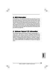
... the User Manual (PDF file) contained in the Support CD. 4. otherwise, POST continues with the motherboard contains necessary drivers and useful utilities that will display the Main Menu automatically if "AUTORUN" is a menu-driven program, which allows you start up the computer, please press during the Power-On-Self-Test (POST) to display the menus. 19 ASRock AD525PV / AD425PV Motherboard English For the detailed information about BIOS Setup, please refer to enter BIOS Setup after POST, please...
... the User Manual (PDF file) contained in the Support CD. 4. otherwise, POST continues with the motherboard contains necessary drivers and useful utilities that will display the Main Menu automatically if "AUTORUN" is a menu-driven program, which allows you start up the computer, please press during the Power-On-Self-Test (POST) to display the menus. 19 ASRock AD525PV / AD425PV Motherboard English For the detailed information about BIOS Setup, please refer to enter BIOS Setup after POST, please...


