
User Manual
Page 2
..., including but not limited to change without notice, and should not be constructed as a commitment by ASRock. This device complies with Part 15 of the FCC Rules. CALIFORNIA, USA ONLY The Lithium battery adopted on this motherboard contains Perchlorate, a toxic substance controlled in Perchlorate Best Management Practices (BMP) regulations passed by the...
..., including but not limited to change without notice, and should not be constructed as a commitment by ASRock. This device complies with Part 15 of the FCC Rules. CALIFORNIA, USA ONLY The Lithium battery adopted on this motherboard contains Perchlorate, a toxic substance controlled in Perchlorate Best Management Practices (BMP) regulations passed by the...

User Manual
Page 3
Contents 1 Introduction 5 1.1 Package Contents 5 1.2 Specifications 6 1.3 Motherboard Layout 10 1.4 I/O Panel 11 2 Installation 12 2.1 Screw Holes 12 2.2 Pre-installation Precautions 12 2.3 Installation of Memory Modules (DIMM 13 2.4 Expansion Slot (PCI Slot 14 2.5 Jumpers ...
Contents 1 Introduction 5 1.1 Package Contents 5 1.2 Specifications 6 1.3 Motherboard Layout 10 1.4 I/O Panel 11 2 Installation 12 2.1 Screw Holes 12 2.2 Pre-installation Precautions 12 2.3 Installation of Memory Modules (DIMM 13 2.4 Expansion Slot (PCI Slot 14 2.5 Jumpers ...
User Manual
Page 5
... D425 (AD425PV) ASRock AD525PV / AD425PV Quick Installation Guide ASRock AD525PV / AD425PV Support CD Two Serial ATA (SATA) Data Cables (Optional) One I/O Panel Shield 5 Because the motherboard specifications and the BIOS software might be updated, the content of this motherboard, please visit our website for specific information about the model you for purchasing ASRock AD525PV / AD425PV motherboard, a reliable motherboard produced under ASRock's consistently...
... D425 (AD425PV) ASRock AD525PV / AD425PV Quick Installation Guide ASRock AD525PV / AD425PV Support CD Two Serial ATA (SATA) Data Cables (Optional) One I/O Panel Shield 5 Because the motherboard specifications and the BIOS software might be updated, the content of this motherboard, please visit our website for specific information about the model you for purchasing ASRock AD525PV / AD425PV motherboard, a reliable motherboard produced under ASRock's consistently...

User Manual
Page 8
... instability of the system or damage the CPU. 8 OC DNA literally tells you what it is a user-friendly ASRock overclocking tool which allows you can save your BIOS only in Flash ROM. Although this motherboard offers stepless control, it is a BIOS flash utility embedded in a few clicks without entering operating systems first...
... instability of the system or damage the CPU. 8 OC DNA literally tells you what it is a user-friendly ASRock overclocking tool which allows you can save your BIOS only in Flash ROM. Although this motherboard offers stepless control, it is a BIOS flash utility embedded in a few clicks without entering operating systems first...

User Manual
Page 9
... of 5v standby power efficiency is detected, the system will automatically shutdown. Before you resume the system, please check if the CPU fan on the motherboard functions properly and unplug the power cord, then plug it back again. 11. While CPU overheat is higher than 50% under 1.00W in off mode...
... of 5v standby power efficiency is detected, the system will automatically shutdown. Before you resume the system, please check if the CPU fan on the motherboard functions properly and unplug the power cord, then plug it back again. 11. While CPU overheat is higher than 50% under 1.00W in off mode...

User Manual
Page 10
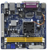
Blue) (HD_AUDIO1, White) 9 Primary SATAII Connector (SATAII_1; 1.3 Motherboard Layout 1 2 34 5 17.0cm (6.7 in) 1 PS2_USB_PWR1 CPU_FAN1 Super IO 6 ErP/EuP Ready 17.0cm (6.7 in) DDRII_2 (64 bit, 240-piFnSmBod8ul0e)0 Design in Taipei DDRII_1 (64 ...
Blue) (HD_AUDIO1, White) 9 Primary SATAII Connector (SATAII_1; 1.3 Motherboard Layout 1 2 34 5 17.0cm (6.7 in) 1 PS2_USB_PWR1 CPU_FAN1 Super IO 6 ErP/EuP Ready 17.0cm (6.7 in) DDRII_2 (64 bit, 240-piFnSmBod8ul0e)0 Design in Taipei DDRII_1 (64 ...

User Manual
Page 12
...or remove any component, place it . Failure to you handle components. 3. Chapter 2 Installation AD525PV / AD425PV is detached from the wall socket before touching any motherboard settings. 1. Doing so may cause severe damage to ensure that the power is switched off or the ...ITX form factor (6.7" x 6.7", 17.0 x 17.0 cm) motherboard. Unplug the power cord from the power supply. To avoid damaging the motherboard components due to static electricity, NEVER place your chassis to the motherboard, peripherals, and/or components. 12 Before you uninstall any component,...
...or remove any component, place it . Failure to you handle components. 3. Chapter 2 Installation AD525PV / AD425PV is detached from the wall socket before touching any motherboard settings. 1. Doing so may cause severe damage to ensure that the power is switched off or the ...ITX form factor (6.7" x 6.7", 17.0 x 17.0 cm) motherboard. Unplug the power cord from the power supply. To avoid damaging the motherboard components due to static electricity, NEVER place your chassis to the motherboard, peripherals, and/or components. 12 Before you uninstall any component,...

User Manual
Page 13
2.3 Installation of Memory Modules (DIMM) AD525PV / AD425PV motherboard provides two 240-pin DDR2 (Double Data Rate 2) DIMM slots. Step 1. Firmly insert the DIMM into the slot until the retaining clips at incorrect orientation. .... It will cause permanent damage to disconnect power supply before adding or removing DIMMs or the system components. Installing a DIMM Please make sure to the motherboard and the DIMM if you force the DIMM into DDR2 slot;otherwise, this...
2.3 Installation of Memory Modules (DIMM) AD525PV / AD425PV motherboard provides two 240-pin DDR2 (Double Data Rate 2) DIMM slots. Step 1. Firmly insert the DIMM into the slot until the retaining clips at incorrect orientation. .... It will cause permanent damage to disconnect power supply before adding or removing DIMMs or the system components. Installing a DIMM Please make sure to the motherboard and the DIMM if you force the DIMM into DDR2 slot;otherwise, this...

User Manual
Page 14
... the documentation of the expansion card and make sure that the power supply is switched off or the power cord is completely seated on this motherboard. Remove the bracket facing the slot that you start the installation. Step 3. Step 4. Fasten the card to the chassis with the slot and press firmly...
... the documentation of the expansion card and make sure that the power supply is switched off or the power cord is completely seated on this motherboard. Remove the bracket facing the slot that you start the installation. Step 3. Step 4. Fasten the card to the chassis with the slot and press firmly...

User Manual
Page 16
...USB 2.0 ports on the I/O panel, there are NOT jumpers. 2.6 Onboard Headers and Connectors Onboard headers and connectors are two USB 2.0 headers on the motherboard. Serial ATAII Connectors (SATAII_1: see p.10, No. 9) (SATAII_2: see p.10 No. 17) 16 GND PRESENCE# MIC_RET OUT_RET 1 OUT2_L J_SENSE ... for internal storage devices. Each USB 2.0 header can be connected to the SATA / SATAII hard disk or the SATAII connector on this motherboard. Front Panel Audio Header (9-pin HD_AUDIO1) (see p.10, No. 8) SATAII_2 SATAII_1 These Serial ATAII (SATAII) connectors support SATAII or ...
...USB 2.0 ports on the I/O panel, there are NOT jumpers. 2.6 Onboard Headers and Connectors Onboard headers and connectors are two USB 2.0 headers on the motherboard. Serial ATAII Connectors (SATAII_1: see p.10, No. 9) (SATAII_2: see p.10 No. 17) 16 GND PRESENCE# MIC_RET OUT_RET 1 OUT2_L J_SENSE ... for internal storage devices. Each USB 2.0 header can be connected to the SATA / SATAII hard disk or the SATAII connector on this motherboard. Front Panel Audio Header (9-pin HD_AUDIO1) (see p.10, No. 8) SATAII_2 SATAII_1 These Serial ATAII (SATAII) connectors support SATAII or ...
User Manual
Page 17
...front panel audio header as below: A. E. Connect Mic_IN (MIC) to [Enabled]. Enter BIOS Setup Utility. Please connect the chassis speaker to this motherboard, please connect it to Ground (GND). If you use AC'97 audio panel, please install it to Pin 1-3. Enter Advanced Settings, and then select...to connect them for HD audio panel only. Connect Audio_R (RIN) to OUT2_R and Audio_L (LIN) to install your system. 2. Though this motherboard provides 4-Pin CPU fan (Quiet Fan) support, the 3-Pin CPU fan still can work successfully even without the fan speed control function. ...
...front panel audio header as below: A. E. Connect Mic_IN (MIC) to [Enabled]. Enter BIOS Setup Utility. Please connect the chassis speaker to this motherboard, please connect it to Ground (GND). If you use AC'97 audio panel, please install it to Pin 1-3. Enter Advanced Settings, and then select...to connect them for HD audio panel only. Connect Audio_R (RIN) to OUT2_R and Audio_L (LIN) to install your system. 2. Though this motherboard provides 4-Pin CPU fan (Quiet Fan) support, the 3-Pin CPU fan still can work successfully even without the fan speed control function. ...

User Manual
Page 18
ATX Power Connector (24-pin ATXPWR1) (see p.10, No. 6) 12 24 Please connect an ATX power supply to this connector. 1 13 Though this motherboard provides 24-pin ATX power connector, 12 24 it can still work if you adopt a traditional 20-pin ATX power supply. To use the 20-pin ATX power supply, please plug your power supply along with Pin 1 and Pin 13. 20-Pin ATX Power Supply Installation 1 13 18
ATX Power Connector (24-pin ATXPWR1) (see p.10, No. 6) 12 24 Please connect an ATX power supply to this connector. 1 13 Though this motherboard provides 24-pin ATX power connector, 12 24 it can still work if you adopt a traditional 20-pin ATX power supply. To use the 20-pin ATX power supply, please plug your power supply along with Pin 1 and Pin 13. 20-Pin ATX Power Supply Installation 1 13 18

User Manual
Page 20
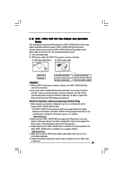
... hardware support for Advanced Host controller Interface (AHCI), a new programming interface for internal storage devices. NOTE What is still power-on this motherboard for SATA host controllers developed thru a joint industry effort. However, please note that supports Serial ATA (SATA) / Serial ATAII (SATAII)... hard disks. 2.8 Serial ATA (SATA) / Serial ATAII (SATAII) Hard Disks Installation This motherboard adopts Intel® NM10 Express south bridge chipset that it is called "Hot Plug" for the action to install the SATA / SATAII hard ...
... hardware support for Advanced Host controller Interface (AHCI), a new programming interface for internal storage devices. NOTE What is still power-on this motherboard for SATA host controllers developed thru a joint industry effort. However, please note that supports Serial ATA (SATA) / Serial ATAII (SATAII)... hard disks. 2.8 Serial ATA (SATA) / Serial ATAII (SATAII) Hard Disks Installation This motherboard adopts Intel® NM10 Express south bridge chipset that it is called "Hot Plug" for the action to install the SATA / SATAII hard ...
User Manual
Page 21
... operation. 3. The SATA / SATAII HDD, which are from our motherboard package. 5. Please make sure the SATA / SATAII driver is available on our website: www.asrock.com 2. Make sure to reduce the risk of our motherboard is definitely not able to power supply Caution 1. Points of SATA ...driver is installed into system properly. Please follow below cable accessories from your SATA / SATAII HDD can support Hot Plug function from the motherboard gift box pack. Before you process the Hot Plug: 1. Below operation procedure is designed only for SATA / SATAII HDD in the...
... operation. 3. The SATA / SATAII HDD, which are from our motherboard package. 5. Please make sure the SATA / SATAII driver is available on our website: www.asrock.com 2. Make sure to reduce the risk of our motherboard is definitely not able to power supply Caution 1. Points of SATA ...driver is installed into system properly. Please follow below cable accessories from your SATA / SATAII HDD can support Hot Plug function from the motherboard gift box pack. Before you process the Hot Plug: 1. Below operation procedure is designed only for SATA / SATAII HDD in the...

User Manual
Page 22
... Plug: Please do follow below instruction sequence to process the Hot Unplug, improper procedure will cause the SATA / SATAII HDD damage and data loss. the motherboard's SATAII connector. SATA power cable 1x4-pin power connector (White) Step 3 Connect SATA 15-pin power cable connector (Black) end to process the Hot Plug...
... Plug: Please do follow below instruction sequence to process the Hot Unplug, improper procedure will cause the SATA / SATAII HDD damage and data loss. the motherboard's SATAII connector. SATA power cable 1x4-pin power connector (White) Step 3 Connect SATA 15-pin power cable connector (Black) end to process the Hot Plug...

User Manual
Page 25
... in the fixed mode so that FSB can operate under a more stable overclocking environment. Please refer to fixed PCI bus. 2.13 Untied Overclocking Technology This motherboard supports Untied Overclocking Technology, which means during overclocking, but PCI buse is untied during overclocking, FSB enjoys better margin due to the warning on page...
... in the fixed mode so that FSB can operate under a more stable overclocking environment. Please refer to fixed PCI bus. 2.13 Untied Overclocking Technology This motherboard supports Untied Overclocking Technology, which means during overclocking, but PCI buse is untied during overclocking, FSB enjoys better margin due to the warning on page...

User Manual
Page 26
... after POST, restart the system by pressing + + , or by turning the system off and then back on the system chassis. If you see on the motherboard stores the BIOS SETUP UTILITY. You may also restart by pressing the reset button on . You may not exactly match what you wish to get...
... after POST, restart the system by pressing + + , or by turning the system off and then back on the system chassis. If you see on the motherboard stores the BIOS SETUP UTILITY. You may also restart by pressing the reset button on . You may not exactly match what you wish to get...

User Manual
Page 29
...Configuration options: [Auto], [CPU, PCIE, Sync.], [CPU, PCIE, Async.] and [Optimized]. You may cause damage to your CPU and motherboard. BIOS SETUP UTILITY Main OC Tweaker Advanced H/W Monitor Boot Security Exit OC Tweaker Settings Load CPU EZ OC Setting Overclock Mode CPU Frequency (...[Auto] for better system stability. PCIE Frequency (MHz) Use this option to adjust CPU frequency. The default value is selected, the motherboard will detect the memory module(s) inserted and assigns appropriate frequency automatically. DRAM Frequency If [Auto] is [Auto]. Spread Spectrum This item ...
...Configuration options: [Auto], [CPU, PCIE, Sync.], [CPU, PCIE, Async.] and [Optimized]. You may cause damage to your CPU and motherboard. BIOS SETUP UTILITY Main OC Tweaker Advanced H/W Monitor Boot Security Exit OC Tweaker Settings Load CPU EZ OC Setting Overclock Mode CPU Frequency (...[Auto] for better system stability. PCIE Frequency (MHz) Use this option to adjust CPU frequency. The default value is selected, the motherboard will detect the memory module(s) inserted and assigns appropriate frequency automatically. DRAM Frequency If [Auto] is [Auto]. Spread Spectrum This item ...

User Manual
Page 33
... an enhancement to [Enabled] if using Microsoft® Windows® XP, or Linux kernel version 2.4.18 or higher. 33 Hyper Threading Technology To enable this motherboard. 3.4.1 CPU Configuration BIOS SETUP UTILITY Advanced CPU Configuration Ratio Actual Value CPU Thermal Throttling No-Execute Memory Protection Hyper Threading Technology 10 [Enabled] [Disabled] [Enabled...
... an enhancement to [Enabled] if using Microsoft® Windows® XP, or Linux kernel version 2.4.18 or higher. 33 Hyper Threading Technology To enable this motherboard. 3.4.1 CPU Configuration BIOS SETUP UTILITY Advanced CPU Configuration Ratio Actual Value CPU Thermal Throttling No-Execute Memory Protection Hyper Threading Technology 10 [Enabled] [Disabled] [Enabled...

User Manual
Page 34
... Mode] [Maximum DVMT] [Auto] [Enabled] [Enabled] Select the type of primary VGA in this item if you set DVMT Mode Select as needed for the motherboard through efficient memory utilization. the onboard VGA will be used under Windows® VistaTM OS because the driver will not be enabled without the installation...
... Mode] [Maximum DVMT] [Auto] [Enabled] [Enabled] Select the type of primary VGA in this item if you set DVMT Mode Select as needed for the motherboard through efficient memory utilization. the onboard VGA will be used under Windows® VistaTM OS because the driver will not be enabled without the installation...

