

User Manual
Page 2
... ONLY The Lithium battery adopted on this documentation, ASRock does not provide warranty of such damages arising from...Version 1.0 Published January 2018 Copyright©2018 ASRock INC. When you discard the Lithium battery in ...BMP) regulations passed by ASRock. This device complies with Part 15 of ASRock Inc. "Perchlorate Material-special.../hazardouswaste/ perchlorate" ASRock Website: http://www.asrock.com All rights reserved. ASRock assumes no event shall ASRock, its directors, ...interruption of business and the like), even if ASRock has been advised of the possibility of any kind...
... ONLY The Lithium battery adopted on this documentation, ASRock does not provide warranty of such damages arising from...Version 1.0 Published January 2018 Copyright©2018 ASRock INC. When you discard the Lithium battery in ...BMP) regulations passed by ASRock. This device complies with Part 15 of ASRock Inc. "Perchlorate Material-special.../hazardouswaste/ perchlorate" ASRock Website: http://www.asrock.com All rights reserved. ASRock assumes no event shall ASRock, its directors, ...interruption of business and the like), even if ASRock has been advised of the possibility of any kind...

User Manual
Page 4
... Contents 1 1.2 Specifications 2 1.3 Motherboard Layout 6 1.4 I/O Panel 8 Chapter 2 Installation 10 2.1 Installing the CPU 11 2.2 Installing the CPU Fan and Heatsink 14 2.3 Installing Memory Modules (DIMM) 15 2.4 Expansion Slots (PCI Express Slots) 17 2.5 Jumpers Setup 18 2.6 Onboard Headers and Connectors 19 Chapter 3 Software and Utilities Operation 27 3.1 Installing Drivers 27 3.2 A-Tuning 28 3.3 ASRock Live Update...
... Contents 1 1.2 Specifications 2 1.3 Motherboard Layout 6 1.4 I/O Panel 8 Chapter 2 Installation 10 2.1 Installing the CPU 11 2.2 Installing the CPU Fan and Heatsink 14 2.3 Installing Memory Modules (DIMM) 15 2.4 Expansion Slots (PCI Express Slots) 17 2.5 Jumpers Setup 18 2.6 Onboard Headers and Connectors 19 Chapter 3 Software and Utilities Operation 27 3.1 Installing Drivers 27 3.2 A-Tuning 28 3.3 ASRock Live Update...
User Manual
Page 6
... will be subject to change without further notice. ASRock website http://www.asrock.com. 1.1 Package Contents • ASRock B360M-HDV Motherboard (Micro ATX Form Factor) • ASRock B360M-HDV Quick Installation Guide • ASRock B360M-HDV Support CD • 1 x I/O Panel Shield • 2 x Serial ATA (SATA) Data Cables (Optional) • 1 x Screw for purchasing ASRock B360M-HDV motherboard, a reliable motherboard produced under ASRock's consistently stringent quality control. Chapter 4 contains the...
... will be subject to change without further notice. ASRock website http://www.asrock.com. 1.1 Package Contents • ASRock B360M-HDV Motherboard (Micro ATX Form Factor) • ASRock B360M-HDV Quick Installation Guide • ASRock B360M-HDV Support CD • 1 x I/O Panel Shield • 2 x Serial ATA (SATA) Data Cables (Optional) • 1 x Screw for purchasing ASRock B360M-HDV motherboard, a reliable motherboard produced under ASRock's consistently stringent quality control. Chapter 4 contains the...
User Manual
Page 11
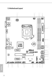
USB 2.0 T: USB1 B: USB2 PS2 Keyboard /Mouse 1.3 Motherboard Layout 1 ATX12V1 2 3 4 CPU_FAN1 CHA_FAN1/WP 5 VGA1 DVI1 ATXPWR1 DDR4_A1 (64 bit, 288-pin module) DDR4_B1 (64 bit, 288-pin module) HDMI1 USB_11_12 USB 3.1 Gen2 T: USB3 B:... USB 3.1 Gen2 Top: T: USB5 B: USB6 RJ-45 LAN Intel B360 CMOS Battery 6 1 7 8 SATA3_5 SATA3_4 Top: LINE IN Center: FRONT Bottom: MIC IN PCIE1 9 BIOS ROM B360M-HDV 10 SATA3_3 SATA3_2 AUDIO CODEC HD_AUDIO1 1 PCIE3 TPMS1 1 1 LPT1 PCIE2 Ultra M.2 PCIe Gen3 x4 CT4 CT3 COM1 1 CT2 CT1 RoHS USB_13_14 1 USB_7_8 1 1 CLRMOS1 CHA_FAN2/WP...
USB 2.0 T: USB1 B: USB2 PS2 Keyboard /Mouse 1.3 Motherboard Layout 1 ATX12V1 2 3 4 CPU_FAN1 CHA_FAN1/WP 5 VGA1 DVI1 ATXPWR1 DDR4_A1 (64 bit, 288-pin module) DDR4_B1 (64 bit, 288-pin module) HDMI1 USB_11_12 USB 3.1 Gen2 T: USB3 B:... USB 3.1 Gen2 Top: T: USB5 B: USB6 RJ-45 LAN Intel B360 CMOS Battery 6 1 7 8 SATA3_5 SATA3_4 Top: LINE IN Center: FRONT Bottom: MIC IN PCIE1 9 BIOS ROM B360M-HDV 10 SATA3_3 SATA3_2 AUDIO CODEC HD_AUDIO1 1 PCIE3 TPMS1 1 1 LPT1 PCIE2 Ultra M.2 PCIe Gen3 x4 CT4 CT3 COM1 1 CT2 CT1 RoHS USB_13_14 1 USB_7_8 1 1 CLRMOS1 CHA_FAN2/WP...

User Manual
Page 15
... object before installing or removing the motherboard components. Before you install the motherboard, study the configuration of the following precautions before you uninstall any motherboard settings. • Make sure to the chassis, please do so may damage the motherboard. 10 English Failure to do not...Doing so may cause physical injuries and damages to motherboard components. • In order to avoid damage from static electricity to ensure that comes with the components. • When placing screws to secure the motherboard to unplug the power cord before you handle the...
... object before installing or removing the motherboard components. Before you install the motherboard, study the configuration of the following precautions before you uninstall any motherboard settings. • Make sure to the chassis, please do so may damage the motherboard. 10 English Failure to do not...Doing so may cause physical injuries and damages to motherboard components. • In order to avoid damage from static electricity to ensure that comes with the components. • When placing screws to secure the motherboard to unplug the power cord before you handle the...

User Manual
Page 18
B360M-HDV Please save and replace the cover if the processor is removed. The cover must be placed if you wish to return the motherboard for after service. 13 English
B360M-HDV Please save and replace the cover if the processor is removed. The cover must be placed if you wish to return the motherboard for after service. 13 English

User Manual
Page 20
... in one memory module installed. 3. It is unable to install identical (the same brand, speed, size and chip-type) DDR4 DIMM pairs. 2. B360M-HDV 2.3 Installing Memory Modules (DIMM) This motherboard provides two 288-pin DDR4 (Double Data Rate 4) DIMM slots, and supports Dual Channel Memory Technology. 1. For dual channel configuration, you force the...
... in one memory module installed. 3. It is unable to install identical (the same brand, speed, size and chip-type) DDR4 DIMM pairs. 2. B360M-HDV 2.3 Installing Memory Modules (DIMM) This motherboard provides two 288-pin DDR4 (Double Data Rate 4) DIMM slots, and supports Dual Channel Memory Technology. 1. For dual channel configuration, you force the...

User Manual
Page 22
... (PCIe 3.0 x16 slot) is used for the card before you start the installation. PCIe slots: PCIE1 (PCIe 3.0 x1 slot) is unplugged. B360M-HDV 2.4 Expansion Slots (PCI Express Slots) There are 3 PCI Express slots on the motherboard. Before installing an expansion card, please make necessary hardware settings for PCI Express x1 lane width cards.
... (PCIe 3.0 x16 slot) is used for the card before you start the installation. PCIe slots: PCIE1 (PCIe 3.0 x1 slot) is unplugged. B360M-HDV 2.4 Expansion Slots (PCI Express Slots) There are 3 PCI Express slots on the motherboard. Before installing an expansion card, please make necessary hardware settings for PCI Express x1 lane width cards.

User Manual
Page 24
... button and system status indicator on when the system is operating. The front panel design may configure the way to turn off (S5). B360M-HDV 2.6 Onboard Headers and Connectors Onboard headers and connectors are matched correctly. Do NOT place jumper caps over the headers and connectors will cause ...is on the chassis front panel. The LED is reading or writing data. PWRBTN (Power Button): Connect to this header according to the motherboard. Press the reset button to restart the computer if the computer freezes and fails to the power status indicator on the chassis front panel...
... button and system status indicator on when the system is operating. The front panel design may configure the way to turn off (S5). B360M-HDV 2.6 Onboard Headers and Connectors Onboard headers and connectors are matched correctly. Do NOT place jumper caps over the headers and connectors will cause ...is on the chassis front panel. The LED is reading or writing data. PWRBTN (Power Button): Connect to this header according to the motherboard. Press the reset button to restart the computer if the computer freezes and fails to the power status indicator on the chassis front panel...

User Manual
Page 25
...Please connect the chassis power LED and the chassis speaker to 6.0 Gb/s data transfer rate. * If M2_1 is one header on this motherboard. This USB 3.1 Gen1 header can support two ports. English 20 Chassis Intrusion and Speaker Header (7-pin SPK_CI1) (see p.6, No. 18...) USB_PWR PP+ GND DUMMY 1 GND P+ PUSB_PWR There are two USB 2.0 headers on this motherboard. Serial ATA3 Connectors (SATA3_0: see p.6, No. 12) (SATA3_1: see p.6, No. 13) (SATA3_2: see p.6, No. 9) (SATA3_3: see p.6, No. 10) (SATA3_4: ...
...Please connect the chassis power LED and the chassis speaker to 6.0 Gb/s data transfer rate. * If M2_1 is one header on this motherboard. This USB 3.1 Gen1 header can support two ports. English 20 Chassis Intrusion and Speaker Header (7-pin SPK_CI1) (see p.6, No. 18...) USB_PWR PP+ GND DUMMY 1 GND P+ PUSB_PWR There are two USB 2.0 headers on this motherboard. Serial ATA3 Connectors (SATA3_0: see p.6, No. 12) (SATA3_1: see p.6, No. 13) (SATA3_2: see p.6, No. 9) (SATA3_3: see p.6, No. 10) (SATA3_4: ...

User Manual
Page 26
... GND 1 (see p.6, No. 2) FAN_SPEED_CONTROL CPU_FAN_SPEED FAN_VOLTAGE GND 1 2 34 This motherboard provides a 4-Pin CPU fan (Quiet Fan) connector. English 21 B. CPU Fan Connector (4-pin CPU_FAN1) (see p.6, No. 14) This motherboard provides two 4-Pin water cooling chassis fan connectors. D. E. Connect Mic_IN (MIC)... connect it to function correctly. Please follow the instructions in the Realtek Control panel and adjust "Recording Volume". B360M-HDV Front Panel Audio Header (9-pin HD_AUDIO1) (see p.6, No. 22) GND PRESENCE# MIC_RET OUT_RET 1 OUT2_L J_SENSE...
... GND 1 (see p.6, No. 2) FAN_SPEED_CONTROL CPU_FAN_SPEED FAN_VOLTAGE GND 1 2 34 This motherboard provides a 4-Pin CPU fan (Quiet Fan) connector. English 21 B. CPU Fan Connector (4-pin CPU_FAN1) (see p.6, No. 14) This motherboard provides two 4-Pin water cooling chassis fan connectors. D. E. Connect Mic_IN (MIC)... connect it to function correctly. Please follow the instructions in the Realtek Control panel and adjust "Recording Volume". B360M-HDV Front Panel Audio Header (9-pin HD_AUDIO1) (see p.6, No. 22) GND PRESENCE# MIC_RET OUT_RET 1 OUT2_L J_SENSE...

User Manual
Page 27
To use a 4-pin ATX power supply, please plug it along Pin 1 and Pin 5. GN D English 22 This motherboard provides an 8-pin ATX 12V power connector. TPM Header (17-pin TPMS1) (see p.6, No. 20) AFD# ERROR# PINIT# SLIN# GND 1 SPD7 SPD6 ACK# SPD5 BUSY ... Power Connector (8-pin ATX12V1) (see p.6, No. 1) 1 13 8 5 4 1 Serial Port Header (9-pin COM1) (see p.6, No. 19) RRXD1 DDTR#1 DDSR#1 CCTS#1 1 RRI#1 RRTS#1 GND TTXD1 DDCD#1 This motherboard provides a 24-pin ATX power connector. To use a 20-pin ATX power supply, please plug it along Pin 1 and Pin 13.
To use a 4-pin ATX power supply, please plug it along Pin 1 and Pin 5. GN D English 22 This motherboard provides an 8-pin ATX 12V power connector. TPM Header (17-pin TPMS1) (see p.6, No. 20) AFD# ERROR# PINIT# SLIN# GND 1 SPD7 SPD6 ACK# SPD5 BUSY ... Power Connector (8-pin ATX12V1) (see p.6, No. 1) 1 13 8 5 4 1 Serial Port Header (9-pin COM1) (see p.6, No. 19) RRXD1 DDTR#1 DDSR#1 CCTS#1 1 RRI#1 RRTS#1 GND TTXD1 DDCD#1 This motherboard provides a 24-pin ATX power connector. To use a 20-pin ATX power supply, please plug it along Pin 1 and Pin 13.
User Manual
Page 29
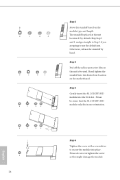
... Step 5 if you are going to secure the module into place. Step 5 Gently insert the M.2 (NGFF) SSD module into the desired nut location on the motherboard. Please be used. D C B A D C B A D C B A Step 3 Move the standoff based on the nut to be aware that the M.2 (NGFF) SSD module only fits in one orientation. The...
... Step 5 if you are going to secure the module into place. Step 5 Gently insert the M.2 (NGFF) SSD module into the desired nut location on the motherboard. Please be used. D C B A D C B A D C B A Step 3 Move the standoff based on the nut to be aware that the M.2 (NGFF) SSD module only fits in one orientation. The...
User Manual
Page 32
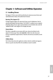
B360M-HDV Chapter 3 Software and Utilities Operation 3.1 Installing Drivers The Support CD that comes with the motherboard contains necessary drivers and useful utilities that the motherboard supports. The CD automatically displays the Main Menu if "AUTORUN" is enabled in the Support CD to your system will be auto-detected and listed ... then follow the order from top to bottom to install it. 27 English Utilities Menu The Utilities Menu shows the application software that enhance the motherboard's features.
B360M-HDV Chapter 3 Software and Utilities Operation 3.1 Installing Drivers The Support CD that comes with the motherboard contains necessary drivers and useful utilities that the motherboard supports. The CD automatically displays the Main Menu if "AUTORUN" is enabled in the Support CD to your system will be auto-detected and listed ... then follow the order from top to bottom to install it. 27 English Utilities Menu The Utilities Menu shows the application software that enhance the motherboard's features.

User Manual
Page 36
... image to perform job-related tasks. Click on your ASRock computer. B360M-HDV 3.3 ASRock Live Update & APP Shop The ASRock Live Update & APP Shop is an online store for purchasing and downloading software applications for your desktop to access ASRock Live Update & APP Shop *You need to be ... selected the information panel below displays the relative information. With ASRock Live Update & APP Shop, you can quickly and easily install various apps and support utilities. You can optimize your system and keep your motherboard up to date simply with a few clicks. Information Panel:...
... image to perform job-related tasks. Click on your ASRock computer. B360M-HDV 3.3 ASRock Live Update & APP Shop The ASRock Live Update & APP Shop is an online store for purchasing and downloading software applications for your desktop to access ASRock Live Update & APP Shop *You need to be ... selected the information panel below displays the relative information. With ASRock Live Update & APP Shop, you can quickly and easily install various apps and support utilities. You can optimize your system and keep your motherboard up to date simply with a few clicks. Information Panel:...
User Manual
Page 49
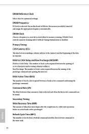
... and Row Precharge (tRCDtRP) RAS# to clock delay for optimized settings. DRAM Clock controls memory training only if ASRock Timing Optimization is selected and when the first active command can be issued. DRAM Frequency If [Auto] is selected, the motherboard will detect the memory module(s) inserted and assign the appropriate frequency automatically.
... and Row Precharge (tRCDtRP) RAS# to clock delay for optimized settings. DRAM Clock controls memory training only if ASRock Timing Optimization is selected and when the first active command can be issued. DRAM Frequency If [Auto] is selected, the motherboard will detect the memory module(s) inserted and assign the appropriate frequency automatically.
User Manual
Page 69
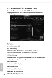
... a fan mode for CPU Fans 1&2, or choose Customize to monitor the status of the hardware on your system, including the parameters of the CPU temperature, motherboard temperature, fan speed and voltage. 4.8 Hardware Health Event Monitoring Screen This section allows you to set 5 CPU temperatures and assign a respective fan speed for each...
... a fan mode for CPU Fans 1&2, or choose Customize to monitor the status of the hardware on your system, including the parameters of the CPU temperature, motherboard temperature, fan speed and voltage. 4.8 Hardware Health Event Monitoring Screen This section allows you to set 5 CPU temperatures and assign a respective fan speed for each...

User Manual
Page 70
... the motherboard is overheated. Case Open Feature Enable or disable Case Open Feature to set 5 CPU temperatures and assign a respective fan speed for Chassis Fan 1, or choose Customize to detect whether the chassis cover has been removed. 65 English Chassis Fan 1 Step Up Set the value of Chassis Fan 1 Step Down. B360M-HDV...
... the motherboard is overheated. Case Open Feature Enable or disable Case Open Feature to set 5 CPU temperatures and assign a respective fan speed for Chassis Fan 1, or choose Customize to detect whether the chassis cover has been removed. 65 English Chassis Fan 1 Step Up Set the value of Chassis Fan 1 Step Down. B360M-HDV...

User Manual
Page 77
..., 2017 DECLARATION OF CONFORMITY Per FCC Part 2 Section 2.1077(a) Responsible Party Name: ASRock Incorporation Address: 13848 Magnolia Ave, Chino, CA91710 Phone/Fax No: +1-909-590-8308/+1-909-590-1026 hereby declares that the product Product Name : Motherboard Model Number : B360M-HDV Conforms to the following speci cations: FCC Part15, SubpartB,Unintentional Radiators Supplementary Information...
..., 2017 DECLARATION OF CONFORMITY Per FCC Part 2 Section 2.1077(a) Responsible Party Name: ASRock Incorporation Address: 13848 Magnolia Ave, Chino, CA91710 Phone/Fax No: +1-909-590-8308/+1-909-590-1026 hereby declares that the product Product Name : Motherboard Model Number : B360M-HDV Conforms to the following speci cations: FCC Part15, SubpartB,Unintentional Radiators Supplementary Information...

User Manual
Page 78
Directive 2011/65/EU ڛCE marking (EU conformity marking) ASRock EUROPE B.V. (Company Name) Bijsterhuizen 1111 6546 AR Nijmegen The Netherlands (Company Address) Person responsible for making this declaration: (Name, Surname) A.V.P (Position / Title) March 9, ...; EN 60950-1 : 2011+ A2: 2013 ☐ EN 60950-1 : 2006/A12: 2011 ڛRoHS - EU Declaration of Conformity For the following equipment: Motherboard (Product Name) B360M-HDV / ASRock (Model Designation / Trade Name) ASRock Incorporation (Manufacturer Name) 2F., No.37, Sec. 2, Jhongyang S.
Directive 2011/65/EU ڛCE marking (EU conformity marking) ASRock EUROPE B.V. (Company Name) Bijsterhuizen 1111 6546 AR Nijmegen The Netherlands (Company Address) Person responsible for making this declaration: (Name, Surname) A.V.P (Position / Title) March 9, ...; EN 60950-1 : 2011+ A2: 2013 ☐ EN 60950-1 : 2006/A12: 2011 ڛRoHS - EU Declaration of Conformity For the following equipment: Motherboard (Product Name) B360M-HDV / ASRock (Model Designation / Trade Name) ASRock Incorporation (Manufacturer Name) 2F., No.37, Sec. 2, Jhongyang S.


