
Intel Rapid Storage Guide
Page 12
... a RAID volume. 1. Create a RAID Volume Use the following steps to RAID. 5. Press Enter to enable RAID in System BIOS Use the instructions included with your motherboard to select the physical disks. 6. Use the up or down arrow keys to select the strip size and press Enter. 5. The F6 installation method is...
... a RAID volume. 1. Create a RAID Volume Use the following steps to RAID. 5. Press Enter to enable RAID in System BIOS Use the instructions included with your motherboard to select the physical disks. 6. Use the up or down arrow keys to select the strip size and press Enter. 5. The F6 installation method is...

RAID Installation Guide
Page 2
This section will guide you how to SATA Hard Disks Installation 1.1 Serial ATA (SATA) Hard Disks Installation Intel chipset supports Serial ATA (SATA) hard disks with RAID functions, including RAID 0, RAID 1, RAID 5, RAID 10 and Intel Rapid Storage. You may install SATA hard disks on SATA ports. 2 1. Please read the RAID configurations in this motherboard for internal storage devices. Guide to create RAID on this guide carefully according to the Intel southbridge chipset that your motherboard adopts.
This section will guide you how to SATA Hard Disks Installation 1.1 Serial ATA (SATA) Hard Disks Installation Intel chipset supports Serial ATA (SATA) hard disks with RAID functions, including RAID 0, RAID 1, RAID 5, RAID 10 and Intel Rapid Storage. You may install SATA hard disks on SATA ports. 2 1. Please read the RAID configurations in this motherboard for internal storage devices. Guide to create RAID on this guide carefully according to the Intel southbridge chipset that your motherboard adopts.

RAID Installation Guide
Page 3
... Mirroring) RAID 1 is called data striping that copies and maintains an identical image of the RAID 0 Disk will introduce the basic knowledge of RAID This motherboard adopts Intel southbridge chipset that integrates RAID controller supporting RAID 0 / RAID 1/ Intel Rapid Storage / RAID 10 / RAID 5 function with four independent Serial ATA (SATA) channels...
... Mirroring) RAID 1 is called data striping that copies and maintains an identical image of the RAID 0 Disk will introduce the basic knowledge of RAID This motherboard adopts Intel southbridge chipset that integrates RAID controller supporting RAID 0 / RAID 1/ Intel Rapid Storage / RAID 10 / RAID 5 function with four independent Serial ATA (SATA) channels...

RAID Installation Guide
Page 23
... steps below. STEP 1: Copy Intel® RAID drivers into a USB flash disk You can download the drivers from ASRock's website and unzip the files into a USB flash disk or copy the files from ASRock's motherboard support CD. (Please copy the files under the following directory: 32 bit: ..\i386\Win7_Intel.. 64-bit: ..\AMD64\Win7...
... steps below. STEP 1: Copy Intel® RAID drivers into a USB flash disk You can download the drivers from ASRock's website and unzip the files into a USB flash disk or copy the files from ASRock's motherboard support CD. (Please copy the files under the following directory: 32 bit: ..\i386\Win7_Intel.. 64-bit: ..\AMD64\Win7...
RAID Installation Guide
Page 25
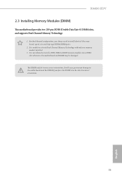
...; or install driver/utilities. E. Reboot your system. (It may take more time to reboot.) D. Windows® will need to follow the instructions below to install motherboard drivers and utilities. 25 Please start to fix this problem. If you encounter this problem, you install Windows® 10 64-bit on a large hard...
...; or install driver/utilities. E. Reboot your system. (It may take more time to reboot.) D. Windows® will need to follow the instructions below to install motherboard drivers and utilities. 25 Please start to fix this problem. If you encounter this problem, you install Windows® 10 64-bit on a large hard...
Quick Installation Guide
Page 1
... the purchaser for informational use only and subject to infringe. With respect to the contents of this documentation, ASRock does not provide warranty of any interference received, including interference that may not be registered trademarks or copyrights of.../ perchlorate" ASRock Website: http://www.asrock.com Version 1.0 Published February 2018 Copyright©2018 ASRock INC. All rights reserved. Disclaimer: Specifications and information contained in any form or by the California Legislature. Products and corporate names appearing in this motherboard contains Perchlorate,...
... the purchaser for informational use only and subject to infringe. With respect to the contents of this documentation, ASRock does not provide warranty of any interference received, including interference that may not be registered trademarks or copyrights of.../ perchlorate" ASRock Website: http://www.asrock.com Version 1.0 Published February 2018 Copyright©2018 ASRock INC. All rights reserved. Disclaimer: Specifications and information contained in any form or by the California Legislature. Products and corporate names appearing in this motherboard contains Perchlorate,...

Quick Installation Guide
Page 3
VGA1 DVI1 USB 2.0 T: USB1 B: USB2 PS2 Keyboard /Mouse Motherboard Layout 1 ATX12V1 B360M-HDV 2 3 4 CPU_FAN1 CHA_FAN1/WP 5 ATXPWR1 DDR4_A1 (64 bit, 288-pin module) DDR4_B1 (64 bit, 288-pin module) HDMI1 USB_11_12 USB 3.1 Gen2 T: USB3 B: USB4 USB 3.1...: T: USB5 B: USB6 RJ-45 LAN Intel B360 CMOS Battery 6 1 7 8 SATA3_5 SATA3_4 Top: LINE IN Center: FRONT Bottom: MIC IN PCIE1 9 BIOS ROM B360M-HDV 10 SATA3_3 SATA3_2 AUDIO CODEC HD_AUDIO1 1 PCIE3 TPMS1 1 1 LPT1 PCIE2 Ultra M.2 PCIe Gen3 x4 CT4 CT3 COM1 1 CT2 CT1 RoHS USB_13_14 1 USB_7_8 1 1 CLRMOS1 CHA_FAN2...
VGA1 DVI1 USB 2.0 T: USB1 B: USB2 PS2 Keyboard /Mouse Motherboard Layout 1 ATX12V1 B360M-HDV 2 3 4 CPU_FAN1 CHA_FAN1/WP 5 ATXPWR1 DDR4_A1 (64 bit, 288-pin module) DDR4_B1 (64 bit, 288-pin module) HDMI1 USB_11_12 USB 3.1 Gen2 T: USB3 B: USB4 USB 3.1...: T: USB5 B: USB6 RJ-45 LAN Intel B360 CMOS Battery 6 1 7 8 SATA3_5 SATA3_4 Top: LINE IN Center: FRONT Bottom: MIC IN PCIE1 9 BIOS ROM B360M-HDV 10 SATA3_3 SATA3_2 AUDIO CODEC HD_AUDIO1 1 PCIE3 TPMS1 1 1 LPT1 PCIE2 Ultra M.2 PCIe Gen3 x4 CT4 CT3 COM1 1 CT2 CT1 RoHS USB_13_14 1 USB_7_8 1 1 CLRMOS1 CHA_FAN2...

Quick Installation Guide
Page 7
... will be available on ASRock's website as well. ASRock website http://www.asrock.com. 1.1 Package Contents • ASRock B360M-HDV Motherboard (Micro ATX Form Factor) • ASRock B360M-HDV Quick Installation Guide • ASRock B360M-HDV Support CD • 1 x I/O Panel Shield • 2 x Serial ATA (SATA) Data Cables (Optional) • 1 x Screw for purchasing ASRock B360M-HDV motherboard, a reliable motherboard produced under ASRock's consistently stringent quality control...
... will be available on ASRock's website as well. ASRock website http://www.asrock.com. 1.1 Package Contents • ASRock B360M-HDV Motherboard (Micro ATX Form Factor) • ASRock B360M-HDV Quick Installation Guide • ASRock B360M-HDV Support CD • 1 x I/O Panel Shield • 2 x Serial ATA (SATA) Data Cables (Optional) • 1 x Screw for purchasing ASRock B360M-HDV motherboard, a reliable motherboard produced under ASRock's consistently stringent quality control...

Quick Installation Guide
Page 12
... and do not touch the ICs. • Whenever you uninstall any motherboard settings. • Make sure to unplug the power cord before you install the motherboard, study the configuration of the following precautions before installing or removing the motherboard components. Before you install motherboard components or change any components, place them on a carpet. Failure...
... and do not touch the ICs. • Whenever you uninstall any motherboard settings. • Make sure to unplug the power cord before you install the motherboard, study the configuration of the following precautions before installing or removing the motherboard components. Before you install motherboard components or change any components, place them on a carpet. Failure...

Quick Installation Guide
Page 15
B360M-HDV Please save and replace the cover if the processor is removed. The cover must be placed if you wish to return the motherboard for after service. 13 English
B360M-HDV Please save and replace the cover if the processor is removed. The cover must be placed if you wish to return the motherboard for after service. 13 English
Quick Installation Guide
Page 17
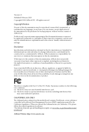
... will cause permanent damage to install a DDR, DDR2 or DDR3 memory module into the slot at incorrect orientation. 15 English otherwise, this motherboard and DIMM may be damaged. The DIMM only fits in one memory module installed. 3. For dual channel configuration, you force the DIMM into... a DDR4 slot; It is not allowed to the motherboard and the DIMM if you always need to activate Dual Channel Memory Technology with only one correct orientation. B360M-HDV 2.3 Installing Memory Modules (DIMM) This motherboard provides two 288-pin DDR4 (Double Data Rate 4) DIMM slots...
... will cause permanent damage to install a DDR, DDR2 or DDR3 memory module into the slot at incorrect orientation. 15 English otherwise, this motherboard and DIMM may be damaged. The DIMM only fits in one memory module installed. 3. For dual channel configuration, you force the DIMM into... a DDR4 slot; It is not allowed to the motherboard and the DIMM if you always need to activate Dual Channel Memory Technology with only one correct orientation. B360M-HDV 2.3 Installing Memory Modules (DIMM) This motherboard provides two 288-pin DDR4 (Double Data Rate 4) DIMM slots...
Quick Installation Guide
Page 19
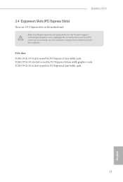
... is switched off or the power cord is used for PCI Express x1 lane width cards. 17 English PCIE3 (PCIe 3.0 x1 slot) is unplugged. B360M-HDV 2.4 Expansion Slots (PCI Express Slots) There are 3 PCI Express slots on the motherboard.
... is switched off or the power cord is used for PCI Express x1 lane width cards. 17 English PCIE3 (PCIe 3.0 x1 slot) is unplugged. B360M-HDV 2.4 Expansion Slots (PCI Express Slots) There are 3 PCI Express slots on the motherboard.

Quick Installation Guide
Page 21
...panel design may configure the way to the power button on the chassis front panel. When connecting your system using the power button. B360M-HDV 2.6 Onboard Headers and Connectors Onboard headers and connectors are matched correctly. You may differ by chassis. The LED keeps blinking when the ...system is reading or writing data. Press the reset button to restart the computer if the computer freezes and fails to the motherboard. PLED (System Power LED): Connect to the pin assignments below. HDLED (Hard Drive Activity LED): Connect to the hard drive activity LED...
...panel design may configure the way to the power button on the chassis front panel. When connecting your system using the power button. B360M-HDV 2.6 Onboard Headers and Connectors Onboard headers and connectors are matched correctly. You may differ by chassis. The LED keeps blinking when the ...system is reading or writing data. Press the reset button to restart the computer if the computer freezes and fails to the motherboard. PLED (System Power LED): Connect to the pin assignments below. HDLED (Hard Drive Activity LED): Connect to the hard drive activity LED...

Quick Installation Guide
Page 22
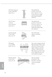
.... 8) (SATA3_5: see p.1, No. 7) SATA3_0 SATA3_2 SATA3_5 SATA3_1 SATA3_3 SATA3_4 These six SATA3 connectors support SATA data cables for internal storage devices with up to this motherboard. USB 3.1 Gen1 Header (19-pin USB_11_12) (see p.1, No. 6) Vbus IntA_P2_SSRXIntA_P2_SSRX+ GND IntA_P2_SSTXIntA_P2_SSTX+ GND IntA_P2_DIntA_P2_D+ Vbus IntA_P3_SSRXIntA_P3_SSRX+ GND IntA_P3_SSTXIntA_P3_SSTX+ GND IntA_P3_DIntA_P3_D+ ID 1 There is ... GND DUMMY Please connect the chassis power LED and the chassis speaker to 6.0 Gb/s data transfer rate. * If M2_1 is one header on this motherboard.
.... 8) (SATA3_5: see p.1, No. 7) SATA3_0 SATA3_2 SATA3_5 SATA3_1 SATA3_3 SATA3_4 These six SATA3 connectors support SATA data cables for internal storage devices with up to this motherboard. USB 3.1 Gen1 Header (19-pin USB_11_12) (see p.1, No. 6) Vbus IntA_P2_SSRXIntA_P2_SSRX+ GND IntA_P2_SSTXIntA_P2_SSTX+ GND IntA_P2_DIntA_P2_D+ Vbus IntA_P3_SSRXIntA_P3_SSRX+ GND IntA_P3_SSTXIntA_P3_SSTX+ GND IntA_P3_DIntA_P3_D+ ID 1 There is ... GND DUMMY Please connect the chassis power LED and the chassis speaker to 6.0 Gb/s data transfer rate. * If M2_1 is one header on this motherboard.

Quick Installation Guide
Page 23
... MIC2_R MIC2_L This header is for connecting audio devices to Pin 1-3. B360M-HDV Front Panel Audio Header (9-pin HD_AUDIO1) (see p.1, No. 2) FAN_SPEED_CONTROL CPU_FAN_SPEED FAN_VOLTAGE GND 1 2 34 This motherboard provides a 4-Pin CPU fan (Quiet Fan) connector. English 21 Chassis/...FAN_VOLTAGE FAN_SPEED FAN_SPEED_CONTROL 1 2 34 FAN_SPEED_CONTROL 4 CHA_FAN_SPEED 3 (4-pin CHA_FAN2/WP) FAN_VOLTAGE 2 GND 1 (see p.1, No. 14) This motherboard provides two 4-Pin water cooling chassis fan connectors. If you use an AC'97 audio panel, please install it to the front audio panel...
... MIC2_R MIC2_L This header is for connecting audio devices to Pin 1-3. B360M-HDV Front Panel Audio Header (9-pin HD_AUDIO1) (see p.1, No. 2) FAN_SPEED_CONTROL CPU_FAN_SPEED FAN_VOLTAGE GND 1 2 34 This motherboard provides a 4-Pin CPU fan (Quiet Fan) connector. English 21 Chassis/...FAN_VOLTAGE FAN_SPEED FAN_SPEED_CONTROL 1 2 34 FAN_SPEED_CONTROL 4 CHA_FAN_SPEED 3 (4-pin CHA_FAN2/WP) FAN_VOLTAGE 2 GND 1 (see p.1, No. 14) This motherboard provides two 4-Pin water cooling chassis fan connectors. If you use an AC'97 audio panel, please install it to the front audio panel...
Quick Installation Guide
Page 24
... (8-pin ATX12V1) (see p.1, No. 1) 1 13 8 5 4 1 Serial Port Header (9-pin COM1) (see p.1, No. 19) RRXD1 DDTR#1 DDSR#1 CCTS#1 1 RRI#1 RRTS#1 GND TTXD1 DDCD#1 This motherboard provides a 24-pin ATX power connector. This motherboard provides an 8-pin ATX 12V power connector. To use a 4-pin ATX power supply, please plug it along Pin 1 and Pin 5.
... (8-pin ATX12V1) (see p.1, No. 1) 1 13 8 5 4 1 Serial Port Header (9-pin COM1) (see p.1, No. 19) RRXD1 DDTR#1 DDSR#1 CCTS#1 1 RRI#1 RRTS#1 GND TTXD1 DDCD#1 This motherboard provides a 24-pin ATX power connector. This motherboard provides an 8-pin ATX 12V power connector. To use a 4-pin ATX power supply, please plug it along Pin 1 and Pin 5.
Quick Installation Guide
Page 26
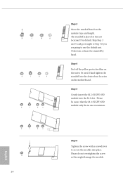
... module. Otherwise, release the standoff by default. English The standoff is placed at the nut location D by hand. D C B A D C B A D C B A Step 3 Move the standoff based on the motherboard.
... module. Otherwise, release the standoff by default. English The standoff is placed at the nut location D by hand. D C B A D C B A D C B A Step 3 Move the standoff based on the motherboard.

Quick Installation Guide
Page 155
... 2.1077(a) Responsible Party Name: ASRock Incorporation Address: 13848 Magnolia Ave, Chino, CA91710 Phone/Fax No: +1-909-590-8308/+1-909-590-1026 hereby declares that may not cause harmful interference, and (2) this device must accept any interference received, including interference that the product Product Name : Motherboard Model Number : B360M-HDV Conforms to the following...
... 2.1077(a) Responsible Party Name: ASRock Incorporation Address: 13848 Magnolia Ave, Chino, CA91710 Phone/Fax No: +1-909-590-8308/+1-909-590-1026 hereby declares that may not cause harmful interference, and (2) this device must accept any interference received, including interference that the product Product Name : Motherboard Model Number : B360M-HDV Conforms to the following...

Quick Installation Guide
Page 156
Directive 2011/65/EU ڛCE marking (EU conformity marking) ASRock EUROPE B.V. (Company Name) Bijsterhuizen 1111 6546 AR Nijmegen The Netherlands (Company Address) Person responsible for making this declaration: (Name, Surname) A.V.P (Position / Title) March 9, 2018...; EN 60950-1 : 2011+ A2: 2013 ☐ EN 60950-1 : 2006/A12: 2011 ڛRoHS - EU Declaration of Conformity For the following equipment: Motherboard (Product Name) B360M-HDV / ASRock (Model Designation / Trade Name) ASRock Incorporation (Manufacturer Name) 2F., No.37, Sec. 2, Jhongyang S.
Directive 2011/65/EU ڛCE marking (EU conformity marking) ASRock EUROPE B.V. (Company Name) Bijsterhuizen 1111 6546 AR Nijmegen The Netherlands (Company Address) Person responsible for making this declaration: (Name, Surname) A.V.P (Position / Title) March 9, 2018...; EN 60950-1 : 2011+ A2: 2013 ☐ EN 60950-1 : 2006/A12: 2011 ڛRoHS - EU Declaration of Conformity For the following equipment: Motherboard (Product Name) B360M-HDV / ASRock (Model Designation / Trade Name) ASRock Incorporation (Manufacturer Name) 2F., No.37, Sec. 2, Jhongyang S.

User Manual
Page 2
...must accept any language, in the documentation or product. "Perchlorate Material-special handling may be registered trademarks or copyrights of ASRock Inc. In no responsibility for informational use only and subject to the implied warranties or conditions of the FCC Rules. With... respect to the contents of this motherboard contains Perchlorate, a toxic substance controlled in advance. ASRock assumes no event shall ASRock, its directors, officers, employees, or agents be constructed as a commitment by the purchaser ...
...must accept any language, in the documentation or product. "Perchlorate Material-special handling may be registered trademarks or copyrights of ASRock Inc. In no responsibility for informational use only and subject to the implied warranties or conditions of the FCC Rules. With... respect to the contents of this motherboard contains Perchlorate, a toxic substance controlled in advance. ASRock assumes no event shall ASRock, its directors, officers, employees, or agents be constructed as a commitment by the purchaser ...


