
User Manual
Page 2
.... All rights reserved. Copyright Notice: No part of this documentation may or may appear in this motherboard contains Perchlorate, a toxic substance controlled in this documentation may cause undesired operation. ASRock assumes no event shall ASRock, its directors, officers, employees, or agents be reproduced, transcribed, transmitted, or translated in any language, in advance. In...
.... All rights reserved. Copyright Notice: No part of this documentation may or may appear in this motherboard contains Perchlorate, a toxic substance controlled in this documentation may cause undesired operation. ASRock assumes no event shall ASRock, its directors, officers, employees, or agents be reproduced, transcribed, transmitted, or translated in any language, in advance. In...
User Manual
Page 4
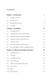
Contents Chapter 1 Introduction 1 1.1 Package Contents 1 1.2 Specifications 2 1.3 Motherboard Layout 6 1.4 I/O Panel 8 Chapter 2 Installation 10 2.1 Installing the CPU 11 2.2 Installing the CPU Fan and Heatsink 13 2.3 Installing Memory Modules (DIMM) 21 2.4 Expansion Slots (... 2.7 M.2_SSD (NGFF) Module Installation Guide 30 Chapter 3 Software and Utilities Operation 34 3.1 Installing Drivers 34 3.2 A-Tuning 35 3.2.1 Installing A-Tuning 35 3.2.2 Using A-Tuning 35 3.3 ASRock Live Update & APP Shop 38 3.3.1 UI Overview 38 3.3.2 Apps 39 3.3.3 BIOS & Drivers 42
Contents Chapter 1 Introduction 1 1.1 Package Contents 1 1.2 Specifications 2 1.3 Motherboard Layout 6 1.4 I/O Panel 8 Chapter 2 Installation 10 2.1 Installing the CPU 11 2.2 Installing the CPU Fan and Heatsink 13 2.3 Installing Memory Modules (DIMM) 21 2.4 Expansion Slots (... 2.7 M.2_SSD (NGFF) Module Installation Guide 30 Chapter 3 Software and Utilities Operation 34 3.1 Installing Drivers 34 3.2 A-Tuning 35 3.2.1 Installing A-Tuning 35 3.2.2 Using A-Tuning 35 3.3 ASRock Live Update & APP Shop 38 3.3.1 UI Overview 38 3.3.2 Apps 39 3.3.3 BIOS & Drivers 42

User Manual
Page 6
ASRock website http://www.asrock.com. 1.1 Package Contents • ASRock B450M-HDV Motherboard (Micro ATX Form Factor) • ASRock B450M-HDV Quick Installation Guide • ASRock B450M-HDV Support CD • 2 x Serial ATA (SATA) Data Cables (Optional) • 1 x Screw for purchasing ASRock B450M-HDV motherboard, a reliable motherboard produced under ASRock's consistently stringent quality control. Chapter 4 contains the configuration guide of the software and utilities. Chapter 3 contains the operation guide...
ASRock website http://www.asrock.com. 1.1 Package Contents • ASRock B450M-HDV Motherboard (Micro ATX Form Factor) • ASRock B450M-HDV Quick Installation Guide • ASRock B450M-HDV Support CD • 2 x Serial ATA (SATA) Data Cables (Optional) • 1 x Screw for purchasing ASRock B450M-HDV motherboard, a reliable motherboard produced under ASRock's consistently stringent quality control. Chapter 4 contains the configuration guide of the software and utilities. Chapter 3 contains the operation guide...

User Manual
Page 11
1.3 Motherboard Layout PS2 Keyboard/ Mouse USB 2.0 T: USB1 B: USB2 ATX12V CPU_FAN1 RoHS DDR4_A1 (64 bit, 288-FpinSBmo8d0ul0e) DDR4_B1 (64 bit, 288-pin module) ATXPWR1 SOCKET AM4 HDMI1 ... 3.1 Gen1 T: USB1 B: USB2 RJ-45 LAN Top: LINE IN Center: FRONT Bottom: MIC IN USB 3.1 Gen1 T: USB3 B: USB4 CMOS Battery CHA_FAN1/WP 1 TPMS1 BIOS ROM B450M-HDV USB3_5_6 1 PCIE1 M2_1 LAN AUDIO CODEC HD_AUDIO1 1 1 COM1 PCIE2 Super I/O CLRCMOS1 1 LPT1 1 CHA_FAN2 SPK_CI1 1 PLED PWRBTN 1 HDLED RESET PANEL1 AMD Promontory B450 SATA3_2 SATA3_1 USB_5_6...
1.3 Motherboard Layout PS2 Keyboard/ Mouse USB 2.0 T: USB1 B: USB2 ATX12V CPU_FAN1 RoHS DDR4_A1 (64 bit, 288-FpinSBmo8d0ul0e) DDR4_B1 (64 bit, 288-pin module) ATXPWR1 SOCKET AM4 HDMI1 ... 3.1 Gen1 T: USB1 B: USB2 RJ-45 LAN Top: LINE IN Center: FRONT Bottom: MIC IN USB 3.1 Gen1 T: USB3 B: USB4 CMOS Battery CHA_FAN1/WP 1 TPMS1 BIOS ROM B450M-HDV USB3_5_6 1 PCIE1 M2_1 LAN AUDIO CODEC HD_AUDIO1 1 1 COM1 PCIE2 Super I/O CLRCMOS1 1 LPT1 1 CHA_FAN2 SPK_CI1 1 PLED PWRBTN 1 HDLED RESET PANEL1 AMD Promontory B450 SATA3_2 SATA3_1 USB_5_6...
User Manual
Page 15
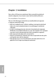
... Chapter 2 Installation This is a Micro ATX form factor motherboard. Doing so may cause physical injuries to you and damages to motherboard components. • In order to avoid damage from static electricity to the motherboard's components, NEVER place your chassis to unplug the power cord... before you uninstall any motherboard settings. • Make sure to ensure that ...
... Chapter 2 Installation This is a Micro ATX form factor motherboard. Doing so may cause physical injuries to you and damages to motherboard components. • In order to avoid damage from static electricity to the motherboard's components, NEVER place your chassis to unplug the power cord... before you uninstall any motherboard settings. • Make sure to ensure that ...
User Manual
Page 18
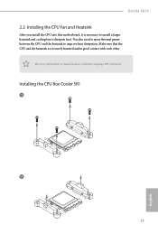
B450M-HDV 2.2 Installing the CPU Fan and Heatsink After you install the CPU into this motherboard, it is necessary to install a larger heatsink and cooling fan to improve heat dissipation. You also need to spray thermal grease between the CPU and the heatsink to dissipate heat. Installing the CPU Box Cooler SR1 1 2 13 English Make sure that the CPU and the heatsink are securely fastened and in good contact with each other. Please turn off the power or remove the power cord before changing a CPU or heatsink.
B450M-HDV 2.2 Installing the CPU Fan and Heatsink After you install the CPU into this motherboard, it is necessary to install a larger heatsink and cooling fan to improve heat dissipation. You also need to spray thermal grease between the CPU and the heatsink to dissipate heat. Installing the CPU Box Cooler SR1 1 2 13 English Make sure that the CPU and the heatsink are securely fastened and in good contact with each other. Please turn off the power or remove the power cord before changing a CPU or heatsink.
User Manual
Page 26
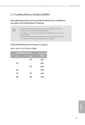
...) 2667 2667 2400 2400 2667 2400 English 21 otherwise, this motherboard and DIMM may be damaged. For dual channel configuration, you always need to install identical (the same brand, speed, size and chip-type) DDR4 DIMM pairs. 2. B450M-HDV 2.3 Installing Memory Modules (DIMM) This motherboard provides two 288-pin DDR4 (Double Data Rate 4) DIMM...
...) 2667 2667 2400 2400 2667 2400 English 21 otherwise, this motherboard and DIMM may be damaged. For dual channel configuration, you always need to install identical (the same brand, speed, size and chip-type) DDR4 DIMM pairs. 2. B450M-HDV 2.3 Installing Memory Modules (DIMM) This motherboard provides two 288-pin DDR4 (Double Data Rate 4) DIMM...

User Manual
Page 28
It will cause permanent damage to the motherboard and the DIMM if you force the DIMM into the slot at incorrect orientation. 1 2 3 23 English B450M-HDV The DIMM only fits in one correct orientation.
It will cause permanent damage to the motherboard and the DIMM if you force the DIMM into the slot at incorrect orientation. 1 2 3 23 English B450M-HDV The DIMM only fits in one correct orientation.
User Manual
Page 29
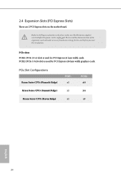
...: PCIE1 (PCIe 2.0 x1 slot) is used for PCI Express x1 lane width cards. 2.4 Expansion Slots (PCI Express Slots) There are 2 PCI Express slots on the motherboard. PCIE2 (PCIe 3.0 x16 slot) is used for the card before you start the installation. Before installing an expansion card, please make necessary hardware settings for...
...: PCIE1 (PCIe 2.0 x1 slot) is used for PCI Express x1 lane width cards. 2.4 Expansion Slots (PCI Express Slots) There are 2 PCI Express slots on the motherboard. PCIE2 (PCIe 3.0 x16 slot) is used for the card before you start the installation. Before installing an expansion card, please make necessary hardware settings for...
User Manual
Page 31
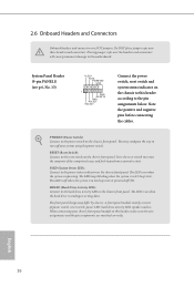
... permanent damage to the power switch on the chassis front panel. Placing jumper caps over these headers and connectors. PWRBTN (Power Switch): Connect to the motherboard. Press the reset switch to restart the computer if the computer freezes and fails to the power status indicator on the chassis front panel. PLED...
... permanent damage to the power switch on the chassis front panel. Placing jumper caps over these headers and connectors. PWRBTN (Power Switch): Connect to the motherboard. Press the reset switch to restart the computer if the computer freezes and fails to the power status indicator on the chassis front panel. PLED...
User Manual
Page 32
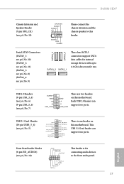
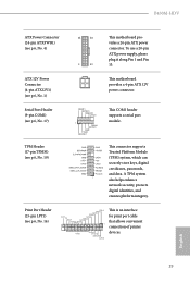
... p.6, No. 18) GND PRESENCE# MIC_RET OUT_RET 1 OUT2_L J_SENSE OUT2_R MIC2_R MIC2_L This header is one header on this motherboard. This USB 3.1 Gen1 header can support two ports. Each USB 2.0 header can support two ports. B450M-HDV Chassis Intrusion and Speaker Header (7-pin SPK_CI1) (see p.6, No. 7) DUMMY GND +B -B USB_PWR GND +A -A USB_PWR 1 There are two...
... p.6, No. 18) GND PRESENCE# MIC_RET OUT_RET 1 OUT2_L J_SENSE OUT2_R MIC2_R MIC2_L This header is one header on this motherboard. This USB 3.1 Gen1 header can support two ports. Each USB 2.0 header can support two ports. B450M-HDV Chassis Intrusion and Speaker Header (7-pin SPK_CI1) (see p.6, No. 7) DUMMY GND +B -B USB_PWR GND +A -A USB_PWR 1 There are two...
User Manual
Page 33
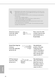
...) to Pin 1-3. MIC_RET and OUT_RET are for the AC'97 audio panel. Chassis Fan Connector (3-pin CHA_FAN2) (see p.6, No. 2) +12V CPU_FAN_SPEED GND FAN_SPEED_CONTROL 1 2 3 4 This motherboard provides a 4-Pin CPU fan (Quiet Fan) connector. If you use an AC'97 audio panel, please install it to MIC2_L. Please follow the instructions in... connect them for the HD audio panel only. Chassis/Water Pump Fan Connector (4-pin CHA_FAN1/WP) (see p.6, No. 20) FAN_SPEED_CONTROL FAN_SPEED FAN_VOLTAGE GND 4 This motherboard 3 2 provides a 4-Pin water 1 cooling chassis fan connector. 1.
...) to Pin 1-3. MIC_RET and OUT_RET are for the AC'97 audio panel. Chassis Fan Connector (3-pin CHA_FAN2) (see p.6, No. 2) +12V CPU_FAN_SPEED GND FAN_SPEED_CONTROL 1 2 3 4 This motherboard provides a 4-Pin CPU fan (Quiet Fan) connector. If you use an AC'97 audio panel, please install it to MIC2_L. Please follow the instructions in... connect them for the HD audio panel only. Chassis/Water Pump Fan Connector (4-pin CHA_FAN1/WP) (see p.6, No. 20) FAN_SPEED_CONTROL FAN_SPEED FAN_VOLTAGE GND 4 This motherboard 3 2 provides a 4-Pin water 1 cooling chassis fan connector. 1.
User Manual
Page 34
...) TPM Header (17-pin TPMS1) (see p.6, No. 4) 12 24 1 13 This motherboard provides a 24-pin ATX power connector. PCIRST# FRAME PCICLK This connector supports Trusted Platform Module (TPM) system, which can securely store keys, digital certificates, passwords, and data. B450M-HDV ATX Power Connector (24-pin ATXPWR1) (see p.6, No. 19) RRXD1 DDTR#1 DDSR...# AFD# This is an interface for print port cable that allows convenient connection of printer devices. Print Port Header (25-pin LPT1) (see p.6, No. 1) This motherboard provides a 4-pin ATX 12V power connector.
...) TPM Header (17-pin TPMS1) (see p.6, No. 4) 12 24 1 13 This motherboard provides a 24-pin ATX power connector. PCIRST# FRAME PCICLK This connector supports Trusted Platform Module (TPM) system, which can securely store keys, digital certificates, passwords, and data. B450M-HDV ATX Power Connector (24-pin ATXPWR1) (see p.6, No. 19) RRXD1 DDTR#1 DDSR...# AFD# This is an interface for print port cable that allows convenient connection of printer devices. Print Port Header (25-pin LPT1) (see p.6, No. 1) This motherboard provides a 4-pin ATX 12V power connector.
User Manual
Page 36
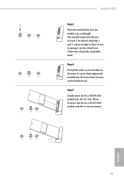
Otherwise, release the standoff by default. Step 4 Peel off the yellow protective film on the motherboard. Please be used. Hand tighten the standoff into the M.2 slot. C B A 20o English 31 Skip Step 3 and 4 and go straight to Step 5 if you are going ... only fits in one orientation. Step 5 Gently insert the M.2 (NGFF) SSD module into the desired nut location on the nut to use the default nut. C B A C B A C B A B450M-HDV Step 3 Move the standoff based on the module type and length. The standoff is placed at the nut location C by hand.
Otherwise, release the standoff by default. Step 4 Peel off the yellow protective film on the motherboard. Please be used. Hand tighten the standoff into the M.2 slot. C B A 20o English 31 Skip Step 3 and 4 and go straight to Step 5 if you are going ... only fits in one orientation. Step 5 Gently insert the M.2 (NGFF) SSD module into the desired nut location on the nut to use the default nut. C B A C B A C B A B450M-HDV Step 3 Move the standoff based on the module type and length. The standoff is placed at the nut location C by hand.
User Manual
Page 39
... Drivers Menu The drivers compatible to display the menu. Utilities Menu The Utilities Menu shows the application software that enhance the motherboard's features. Please click Install All or follow the installation wizard to install those required drivers. Running The Support CD To...work properly. Chapter 3 Software and Utilities Operation 3.1 Installing Drivers The Support CD that comes with the motherboard contains necessary drivers and useful utilities that the motherboard supports. The CD automatically displays the Main Menu if "AUTORUN" is enabled in the Support CD to ...
... Drivers Menu The drivers compatible to display the menu. Utilities Menu The Utilities Menu shows the application software that enhance the motherboard's features. Please click Install All or follow the installation wizard to install those required drivers. Running The Support CD To...work properly. Chapter 3 Software and Utilities Operation 3.1 Installing Drivers The Support CD that comes with the motherboard contains necessary drivers and useful utilities that the motherboard supports. The CD automatically displays the Main Menu if "AUTORUN" is enabled in the Support CD to ...
User Manual
Page 43
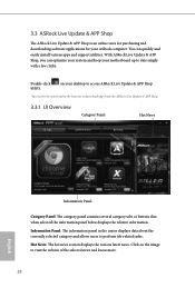
You can optimize your system and keep your motherboard up to perform job-related tasks. With ASRock Live Update & APP Shop, you can quickly and easily install various apps and support utilities. Information Panel: The information panel in the center displays data ... more. 38 English Hot News: The hot news section displays the various latest news. Double-click utility. on the image to download apps from the ASRock Live Update & APP Shop. 3.3.1 UI Overview Category Panel Hot News Information Panel Category Panel: The category panel contains several category tabs or buttons that when...
You can optimize your system and keep your motherboard up to perform job-related tasks. With ASRock Live Update & APP Shop, you can quickly and easily install various apps and support utilities. Information Panel: The information panel in the center displays data ... more. 38 English Hot News: The hot news section displays the various latest news. Double-click utility. on the image to download apps from the ASRock Live Update & APP Shop. 3.3.1 UI Overview Category Panel Hot News Information Panel Category Panel: The category panel contains several category tabs or buttons that when...
User Manual
Page 53
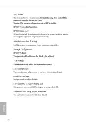
... to [Auto] to save current UEFI settings as user default. DRAM Timing Configuration DRAM Frequency If [Auto] is [Auto]. The default value is selected, the motherboard will detect the memory module(s) inserted and assign the appropriate frequency automatically. Save User UEFI Setup Profile to Disk It helps you to save your...
... to [Auto] to save current UEFI settings as user default. DRAM Timing Configuration DRAM Frequency If [Auto] is [Auto]. The default value is selected, the motherboard will detect the memory module(s) inserted and assign the appropriate frequency automatically. Save User UEFI Setup Profile to Disk It helps you to save your...
User Manual
Page 73
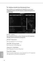
... a fan mode for CPU Fan 1, or choose Customize to monitor the status of the hardware on your system, including the parameters of the CPU temperature, motherboard temperature, fan speed and voltage. CPU Fan 1 Temp Source Select a fan temperature source for Chassis Fan 1.
... a fan mode for CPU Fan 1, or choose Customize to monitor the status of the hardware on your system, including the parameters of the CPU temperature, motherboard temperature, fan speed and voltage. CPU Fan 1 Temp Source Select a fan temperature source for Chassis Fan 1.

User Manual
Page 74
Over Temperature Protection When Over Temperature Protection is enabled, the system automatically shuts down when the motherboard is overheated. Case Open Feature Enable or disable Case Open Feature to detect whether the chassis cover has been removed. 69 English B450M-HDV Chassis Fan 1 Temp Source Select a fan temperature source for Chassis Fan 1.
Over Temperature Protection When Over Temperature Protection is enabled, the system automatically shuts down when the motherboard is overheated. Case Open Feature Enable or disable Case Open Feature to detect whether the chassis cover has been removed. 69 English B450M-HDV Chassis Fan 1 Temp Source Select a fan temperature source for Chassis Fan 1.

User Manual
Page 80
... 2.1077(a) Responsible Party Name: ASRock Incorporation Address: 13848 Magnolia Ave, Chino, CA91710 Phone/Fax No: +1-909-590-8308/+1-909-590-1026 hereby declares that may not cause harmful interference, and (2) this device must accept any interference received, including interference that the product Product Name : Motherboard Model Number : B450M-HDV Conforms to the following speci...
... 2.1077(a) Responsible Party Name: ASRock Incorporation Address: 13848 Magnolia Ave, Chino, CA91710 Phone/Fax No: +1-909-590-8308/+1-909-590-1026 hereby declares that may not cause harmful interference, and (2) this device must accept any interference received, including interference that the product Product Name : Motherboard Model Number : B450M-HDV Conforms to the following speci...


