
Intel Rapid Storage Guide
Page 12
... and press Enter. 4. Select 1: Create RAID Volume and press Enter. 3. Enetr the Advanced menu. 3. Enable RAID in System BIOS Use the instructions included with your motherboard to enable RAID in the system BIOS, a RAID volume must be created, and the F6 installation method must be used to load the Intel®...
... and press Enter. 4. Select 1: Create RAID Volume and press Enter. 3. Enetr the Advanced menu. 3. Enable RAID in System BIOS Use the instructions included with your motherboard to enable RAID in the system BIOS, a RAID volume must be created, and the F6 installation method must be used to load the Intel®...
Intel Smart Response Installation Guide
Page 1
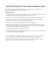
...find the UI setup instruction and the step by double-clicking RST Storage icon in the near future. Intel Smart Response Technology Installation Guide This motherboard supports Intel Smart Response Technology. You MUST have both the HDD you intend to accelerate AND the SSD in RAID ROM. Once open RST ... from either Start Menu or by step instructions below. For the new version RST driver, please check our website for the latest information: http://www.asrock.com * Before you use RST function, you want to use the full SSD as the Cache device, which HDD you wish to Accelerate, if...
...find the UI setup instruction and the step by double-clicking RST Storage icon in the near future. Intel Smart Response Technology Installation Guide This motherboard supports Intel Smart Response Technology. You MUST have both the HDD you intend to accelerate AND the SSD in RAID ROM. Once open RST ... from either Start Menu or by step instructions below. For the new version RST driver, please check our website for the latest information: http://www.asrock.com * Before you use RST function, you want to use the full SSD as the Cache device, which HDD you wish to Accelerate, if...

User Manual
Page 2
... the contents of this manual, ASRock does not provide warranty of any means, except duplication of documentation by the purchaser for backup purpose, without intent to infringe. CALIFORNIA, USA ONLY The Lithium battery adopted on this motherboard contains Perchlorate, a toxic substance... controlled in Perchlorate Best Management Practices (BMP) regulations passed by ASRock. Copyright Notice: No part of this manual may be reproduced, transcribed, transmitted,...
... the contents of this manual, ASRock does not provide warranty of any means, except duplication of documentation by the purchaser for backup purpose, without intent to infringe. CALIFORNIA, USA ONLY The Lithium battery adopted on this motherboard contains Perchlorate, a toxic substance... controlled in Perchlorate Best Management Practices (BMP) regulations passed by ASRock. Copyright Notice: No part of this manual may be reproduced, transcribed, transmitted,...

User Manual
Page 3
Introduction 5 1.1 Package Contents 5 1.2 Specifications 6 1.3 Unique Features 10 1.4 Motherboard Layout (H77M-ITX 13 1.5 Motherboard Layout (B75M-ITX 15 1.6 Motherboard Layout (H61M-ITX 17 1.7 I/O Panel (H77M-ITX 19 1.8 I/O Panel (B75M-ITX 20 1.9 I/O Panel (H61M-ITX 21 2. Installation 22 2.1 Installing the CPU 23 2.2 Installing the CPU Fan and Heatsink 25 2.3 Installing Memory Modules (DIMM 26 2.4 Expansion Slots (PCI Express Slots 27 2.5 ...
Introduction 5 1.1 Package Contents 5 1.2 Specifications 6 1.3 Unique Features 10 1.4 Motherboard Layout (H77M-ITX 13 1.5 Motherboard Layout (B75M-ITX 15 1.6 Motherboard Layout (H61M-ITX 17 1.7 I/O Panel (H77M-ITX 19 1.8 I/O Panel (B75M-ITX 20 1.9 I/O Panel (H61M-ITX 21 2. Installation 22 2.1 Installing the CPU 23 2.2 Installing the CPU Fan and Heatsink 25 2.3 Installing Memory Modules (DIMM 26 2.4 Expansion Slots (PCI Express Slots 27 2.5 ...
User Manual
Page 5
... notice. You may find the latest VGA cards and CPU support list on ASRock's website. www.asrock.com/support/index.asp 1.1 Package Contents ASRock H77TM-ITX / B75TM-ITX / H61TM-ITX Motherboard (Thin Mini-ITX Form Factor: 6.7-in x 6.7-in, 17.0 cm x 17.0 cm) ASRock H77TM-ITX / B75TM-ITX / H61TM-ITX Quick Installation Guide ASRock H77TM-ITX / B75TM-ITX / H61TM-ITX Support CD 1 x I/O Panel Shield 5 In case any modifications of the...
... notice. You may find the latest VGA cards and CPU support list on ASRock's website. www.asrock.com/support/index.asp 1.1 Package Contents ASRock H77TM-ITX / B75TM-ITX / H61TM-ITX Motherboard (Thin Mini-ITX Form Factor: 6.7-in x 6.7-in, 17.0 cm x 17.0 cm) ASRock H77TM-ITX / B75TM-ITX / H61TM-ITX Quick Installation Guide ASRock H77TM-ITX / B75TM-ITX / H61TM-ITX Support CD 1 x I/O Panel Shield 5 In case any modifications of the...

User Manual
Page 22
...from static electricity to the motherboard's components, NEVER place your chassis to the chassis, please do not touch the ICs. 4. When placing screws to secure the motherboard to ensure that comes with ... Precautions Take note of your motherboard directly on a grounded anti-static pad or in the bag that the motherboard fits into it. Failure to motherboard components. 2. Also remember to... unplug the power cord before you and damages to do so may damage the motherboard. 22 Doing so...
...from static electricity to the motherboard's components, NEVER place your chassis to the chassis, please do not touch the ICs. 4. When placing screws to secure the motherboard to ensure that comes with ... Precautions Take note of your motherboard directly on a grounded anti-static pad or in the bag that the motherboard fits into it. Failure to motherboard components. 2. Also remember to... unplug the power cord before you and damages to do so may damage the motherboard. 22 Doing so...

User Manual
Page 24
... will automatically come off by itself. Please save and replace the cover if the processor is within the socket and properly mated to return the motherboard for after service. 24
... will automatically come off by itself. Please save and replace the cover if the processor is within the socket and properly mated to return the motherboard for after service. 24

User Manual
Page 25
...Rotate the fastener clockwise, then press the fastener caps down the fasteners without rotating them clockwise, the heatsink cannot be secured on the motherboard. Connect the CPU fan connector with the remaining fasteners. Before you install the heatsink, you press down with the holes on the...Thermal Interface Material Ensure that the CPU and the heatsink are faced on the side closest to the CPU fan connector on the motherboard (CPU_FAN1, see Fan cables on the motherboard. Repeat with the fan header on side closest to the CPU_FAN connector (CPU_FAN1, see p.13/15/17, No. 22). ...
...Rotate the fastener clockwise, then press the fastener caps down the fasteners without rotating them clockwise, the heatsink cannot be secured on the motherboard. Connect the CPU fan connector with the remaining fasteners. Before you install the heatsink, you press down with the holes on the...Thermal Interface Material Ensure that the CPU and the heatsink are faced on the side closest to the CPU fan connector on the motherboard (CPU_FAN1, see Fan cables on the motherboard. Repeat with the fan header on side closest to the CPU_FAN connector (CPU_FAN1, see p.13/15/17, No. 22). ...

User Manual
Page 26
Step 1. Step 2. Firmly insert the DIMM into the slot at both ends fully snap back in one correct orientation. It will cause permanent damage to the motherboard and the DIMM if you force the DIMM into the slot until the retaining clips at incorrect orientation. Align a DIMM on the slot such that the notch on the DIMM matches the break on the slot. The DIMM only fits in place and the DIMM is properly seated. 26 2.3 Installing Memory Modules (DIMM) This motherboard provides two 204-pin DDR3 (Double Data Rate 3) SODIMM slots.
Step 1. Step 2. Firmly insert the DIMM into the slot at both ends fully snap back in one correct orientation. It will cause permanent damage to the motherboard and the DIMM if you force the DIMM into the slot until the retaining clips at incorrect orientation. Align a DIMM on the slot such that the notch on the DIMM matches the break on the slot. The DIMM only fits in place and the DIMM is properly seated. 26 2.3 Installing Memory Modules (DIMM) This motherboard provides two 204-pin DDR3 (Double Data Rate 3) SODIMM slots.
User Manual
Page 27
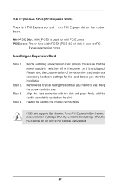
...) is used for the card before you intend to the chassis with the slot and press firmly until the card is completely seated on this motherboard. Step 3. 2.4 Expansion Slots (PCI Express Slots) There is 1 PCI Express slot and 1 mini PCI Express slot on the slot.
...) is used for the card before you intend to the chassis with the slot and press firmly until the card is completely seated on this motherboard. Step 3. 2.4 Expansion Slots (PCI Express Slots) There is 1 PCI Express slot and 1 mini PCI Express slot on the slot.

User Manual
Page 28
SATA2 / SATA3 Connectors (SATA_0: see p.13/15/17, No. 6) SATA_1 (SATA_1: see p.13/15/17, No. 2) SATA_0 These two SATA2 / SATA3 connectors support SATA data cables for internal storage devices. 28 2.5 Installing Serial SATA2 / SATA3 Hard Disks STEP 1: Connect the SATA power cable to the hard disk. STEP 2: Connect one end of the SATA data cable to the motherboard's SATA2 connectors. STEP 3: Connect the other end of the SATA data cable to the hard disk.
SATA2 / SATA3 Connectors (SATA_0: see p.13/15/17, No. 6) SATA_1 (SATA_1: see p.13/15/17, No. 2) SATA_0 These two SATA2 / SATA3 connectors support SATA data cables for internal storage devices. 28 2.5 Installing Serial SATA2 / SATA3 Hard Disks STEP 1: Connect the SATA power cable to the hard disk. STEP 2: Connect one end of the SATA data cable to the motherboard's SATA2 connectors. STEP 3: Connect the other end of the SATA data cable to the hard disk.

User Manual
Page 31
... will cause permanent damage to connect the remote controller receiver. 31 The USB 3.0 header can be used to the motherboard! GND IntA_PB_SSRX+ IntA_PB_SSRX- 2.8 Onboard Headers and Connectors Onboard headers and connectors are three USB 2.0 headers and one USB 3.0 header on this... USB_PWR GND +A -A USB_PWR 1 (9-pin USB6_7) (see p.13/15/17, No. 7) USB_PWR -B +B GND DUMMY 1 GND +A -A USB_PWR Besides two default USB 2.0 ports on this motherboard. Vbus Besides two default USB 3.0 ports on the I/O panel, there is one USB port on the I/O panel, there are NOT jumpers.
... will cause permanent damage to connect the remote controller receiver. 31 The USB 3.0 header can be used to the motherboard! GND IntA_PB_SSRX+ IntA_PB_SSRX- 2.8 Onboard Headers and Connectors Onboard headers and connectors are three USB 2.0 headers and one USB 3.0 header on this... USB_PWR GND +A -A USB_PWR 1 (9-pin USB6_7) (see p.13/15/17, No. 7) USB_PWR -B +B GND DUMMY 1 GND +A -A USB_PWR Besides two default USB 2.0 ports on this motherboard. Vbus Besides two default USB 3.0 ports on the I/O panel, there is one USB port on the I/O panel, there are NOT jumpers.

User Manual
Page 33
... off ). 3W Audio AMP Output Wafer Header (4-pin SPEAKER1) (see p.13/15/17, No. 11) PLEDPLED+ PLED+ 1 Please connect the chassis power LED to this motherboard 3 2 1 provides a 4-Pin CPU fan (Quiet Fan) connector, 3-Pin CPU fans can still work even without fan speed control. The LED keeps blinking in S4 state...
... off ). 3W Audio AMP Output Wafer Header (4-pin SPEAKER1) (see p.13/15/17, No. 11) PLEDPLED+ PLED+ 1 Please connect the chassis power LED to this motherboard 3 2 1 provides a 4-Pin CPU fan (Quiet Fan) connector, 3-Pin CPU fans can still work even without fan speed control. The LED keeps blinking in S4 state...
User Manual
Page 37
Refer your OS documentation for general reference only. 2.10 Operating System Setup This motherboard supports various Microsoft® Windows® operating systems: 8 / 8 64-bit / 7 / 7 64-bit / VistaTM / VistaTM 64-bit / XP / XP 64-bit. Because motherboard settings and hardware options vary, use the setup procedures in this chapter for more information. 37
Refer your OS documentation for general reference only. 2.10 Operating System Setup This motherboard supports various Microsoft® Windows® operating systems: 8 / 8 64-bit / 7 / 7 64-bit / VistaTM / VistaTM 64-bit / XP / XP 64-bit. Because motherboard settings and hardware options vary, use the setup procedures in this chapter for more information. 37
User Manual
Page 38
... necessary drivers and useful utilities that the motherboard supports. The CD automatically displays the Main Menu if "AUTORUN" is enabled in the Support CD to display the menu. 2.11.2 Drivers Menu The drivers compatible to know more about ASRock, you install can work properly. 2.11.3 Utilities... Menu The Utilities Menu shows the application softwares that enhance the motherboard's features. 2.11.1 Running The Support CD To begin using the support CD, ...
... necessary drivers and useful utilities that the motherboard supports. The CD automatically displays the Main Menu if "AUTORUN" is enabled in the Support CD to display the menu. 2.11.2 Drivers Menu The drivers compatible to know more about ASRock, you install can work properly. 2.11.3 Utilities... Menu The Utilities Menu shows the application softwares that enhance the motherboard's features. 2.11.1 Running The Support CD To begin using the support CD, ...

User Manual
Page 39
... the following UEFI setup screens and descriptions are for reference purpose only, and they may run the UEFI SETUP UTILITY when you see on the motherboard stores the UEFI SETUP UTILITY. Because the UEFI software is constantly being updated, the following selections: Main For setting system time/date information OC Tweaker...
... the following UEFI setup screens and descriptions are for reference purpose only, and they may run the UEFI SETUP UTILITY when you see on the motherboard stores the UEFI SETUP UTILITY. Because the UEFI software is constantly being updated, the following selections: Main For setting system time/date information OC Tweaker...

User Manual
Page 42
... change the ratio value of this function, please set up overclocking features. If you can switch between multiple frequencies and voltage points to enable this motherboard. This item will be hidden if the current CPU does not support Intel SpeedStep technology. The default value is Intel's power saving technology. Short Duration...
... change the ratio value of this function, please set up overclocking features. If you can switch between multiple frequencies and voltage points to enable this motherboard. This item will be hidden if the current CPU does not support Intel SpeedStep technology. The default value is Intel's power saving technology. Short Duration...
User Manual
Page 43
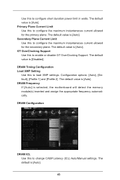
...: [Auto], [Default], [Profile 1] and [Profile 2]. The default value is [Disabled]. Use this to change CAS# Latency (tCL) Auto/Manual settings. The default is selected, the motherboard will detect the memory module(s) inserted and assign the appropriate frequency automatically. Secondary Plane Current Limit Use this to configure the maximum instantaneous current allowed...
...: [Auto], [Default], [Profile 1] and [Profile 2]. The default value is [Disabled]. Use this to change CAS# Latency (tCL) Auto/Manual settings. The default is selected, the motherboard will detect the memory module(s) inserted and assign the appropriate frequency automatically. Secondary Plane Current Limit Use this to configure the maximum instantaneous current allowed...

User Manual
Page 57
... to power on the 57 Check Ready Bit Use this to enable or disable the ACPI HPET Table. 3.4.8 ACPI Configuration Suspend to RAM Use this motherboard to submit Windows® certification. Ring-In Power On Use this to enable or disable the PCI devices to auto-detect or disable Suspend-toRAM...
... to power on the 57 Check Ready Bit Use this to enable or disable the ACPI HPET Table. 3.4.8 ACPI Configuration Suspend to RAM Use this motherboard to submit Windows® certification. Ring-In Power On Use this to enable or disable the PCI devices to auto-detect or disable Suspend-toRAM...

User Manual
Page 63
Configuration options: [Full On] and [Automatic Mode]. The default value is [Full On]. 63 Chassis Fan 1 Setting This allows you to set chassis fan 1's speed. The default value is [Full On]. CPU Fan 1 Setting This allows you to monitor the status of the hardware on your system, including the parameters of the CPU temperature, motherboard temperature, fan speed and voltage. Configuration options: [Full On] and [Automatic Mode]. 3.6 Hardware Health Event Monitoring Screen This section allows you to set CPU fan 1's speed.
Configuration options: [Full On] and [Automatic Mode]. The default value is [Full On]. 63 Chassis Fan 1 Setting This allows you to set chassis fan 1's speed. The default value is [Full On]. CPU Fan 1 Setting This allows you to monitor the status of the hardware on your system, including the parameters of the CPU temperature, motherboard temperature, fan speed and voltage. Configuration options: [Full On] and [Automatic Mode]. 3.6 Hardware Health Event Monitoring Screen This section allows you to set CPU fan 1's speed.

